 |
 |
 |
 |
Week4 . Computer Controlled Cutting
Assignment
group assignment:
- characterize your lasercutter, making test part(s)
that vary cutting settings and dimensions
individual assignment:
- cut something on the vinylcutter
design, lasercut, and document a parametric press-fit construction kit,
accounting for the lasercutter kerf,
which can be assembled in multiple ways
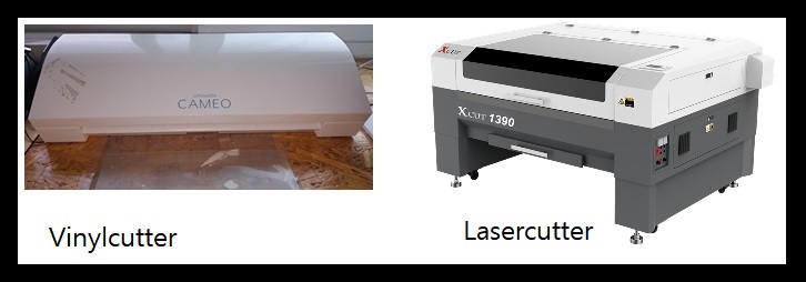
1. Equipment
Vinylcutter
• Hardware: Silhouette CAMEO 3(Silhouette America Inc.)
• Operating Software: Silhouette Studio v3(import format: DXF,USB download or Memory download)
• Design Software:Vector Graphic Editor(InkScape, Adobe illustrator):import format:BMP, output format: DXF
• Material:thin film (Stick Vinyl)
Lasercutter
• Hardware: Xcut1390(Distributer: LaserPix Korea Co.Ltd.)
• Operating Software: LaserWorkV6(USB download or USB memory download)
• Design Software:Vector Graphic or CAD(Parametric): Fusion360, FreeCAD[output format: DXF]
• Material: MDF,Acryl
2. Vinyl cutting
Step1. Making Toolpath
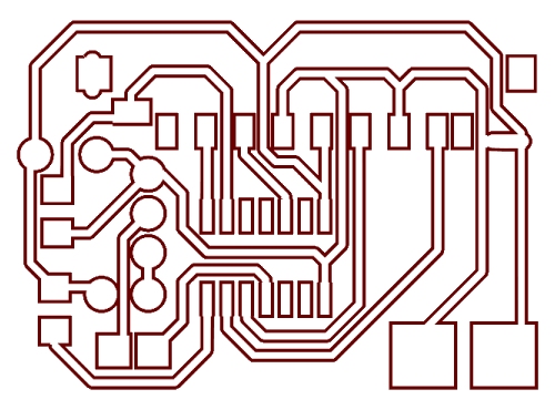
I will try to transfer image to plastic case from a circuit image file.
To get the toolpath, I will use 2D software, first run with InkScape.
This is a based file downloaded from internet :
board_outline.jpg
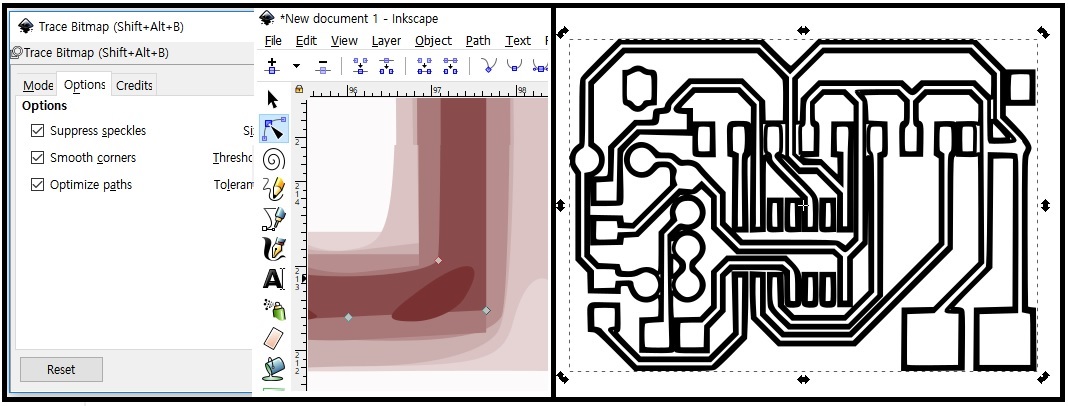
Import image file. To get a base trace image, right click to use 'Trace Bitmap' command.
There are several attribute in drawing(in middle image), I choose stoke(seems to me outline).
Next color change to black, save as dxf format.
Cross check with Adobe illustrator about outline.
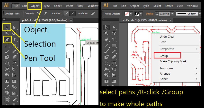
There are some open path, so fix outline and make all closed loop.
These works can be makes by two steps.
a. Before the joining, make sure line shape fit to the orientation will touch that point.
This can be make hold first the path and select 'Pen tool' next 'Add AnchorPort Tool' than
added extra point can be controllable. Than stratch this point to fit well shapes.
And release to the end of open path.
b. And change the pointer to 'Selection Tool' button than grab whole points to join.
Go to the 'Object menu' in top command bar and select 'path/join' command in list menus.
Than these points join and make a connected path.
Again save as dxf format to cut with vinyl cutter.
download files:
pcbPattern.zip
- Inkscape file : pcbEx1_oorigin.svg
- Adobe illustrator file : pcbEx1.ai
- Silhouette file : pcbEx1.dxf
Step 2. Hardware Setting
| Specifications | Settings | ||||||||||||||||||||||||||||||||||||||||||
|---|---|---|---|---|---|---|---|---|---|---|---|---|---|---|---|---|---|---|---|---|---|---|---|---|---|---|---|---|---|---|---|---|---|---|---|---|---|---|---|---|---|---|---|
|
|
||||||||||||||||||||||||||||||||||||||||||
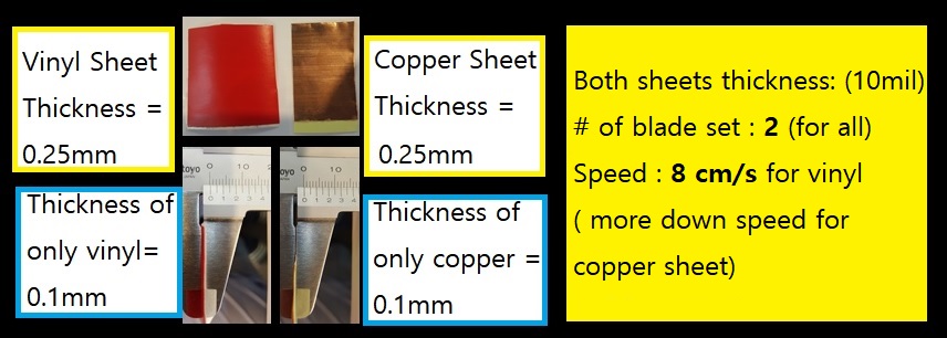
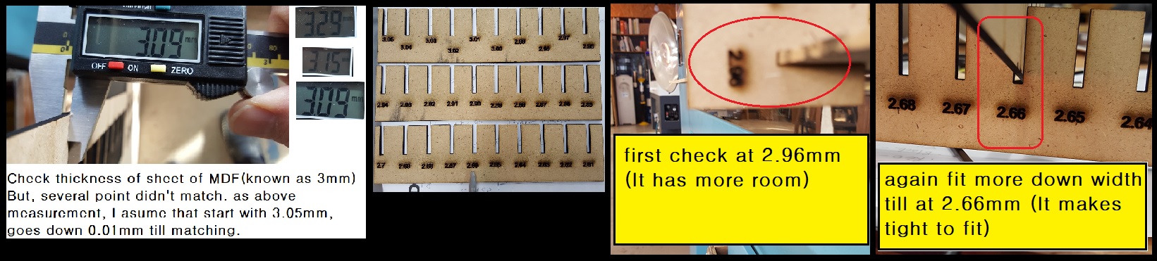
Measure the materials sheet thickness and set the parameters.
Step3. vinylcutter work
Prepare vinylcutter.(I use Silhouette CAMEO.)

Blade Type Explanation 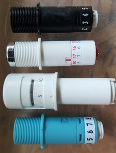
1. Ratchet Blade: Can cut through paper, cardstock,
vinyl etc. Standard type. manual replace the blade.
2. Deep Cut Blade : For thick materials like chipboard,
use this 2 mm long blade.
3. Self Adjusting Blade :For the begineer type, uses
material presets and tapping to self adjust to the blade length.
4. Fabric Blade : this blade like a rachet type, can cut paper and fabric.
I use the 'Self Adjusting Blade' to cut the vinyl sheets.
Setup software parameter. first, page setting and cutting parameters.
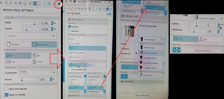
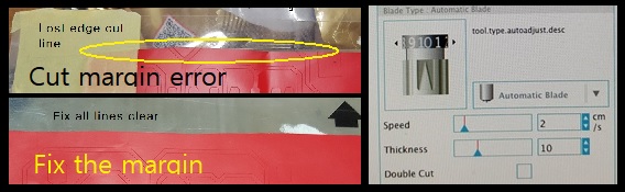
First cut need to be alignment more(upper left image show that missed the start point to cut).
I rearrange to start point and run again(lower left image to show clear to cut of image. ).
Right image shows that control the blade speed lower than normal speed for slitely deep cut.
Step4. Transfer cutting pattern
Finally take off the vinyl film from adhesive sheet is a vinyl cutter accessory.
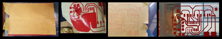
I just stick the paper tape on the vinyl outputs and take off extra parts outside of
patterns. And stick to the top side of plastic case, press the tape and remove the paper tape
carefully. And finally to get the result as I want.
3. Lasercutter
Step 1. How to operating the Xcut1390 lasercutter.
• Hardware settings and operation
This machine can be used for working with non-metal materials.
| Specifications | Reference Settings | ||||||||||||||||||||||||||||||||||||
|---|---|---|---|---|---|---|---|---|---|---|---|---|---|---|---|---|---|---|---|---|---|---|---|---|---|---|---|---|---|---|---|---|---|---|---|---|---|
|
check by experiment. |
• General operation
- 1. Import the dxf file in LaserWorksV6 software.- 2. Check about the shape which is to cut line or engraving.
- 3. If no error were there, make set the parameters of lasercutting.
- 4. Download making toolpath file to the machine.
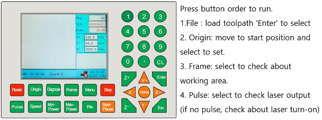
- 5. Than follow the procedure in control pannel of machine follow the below image
Step 2. Making the pressfit.
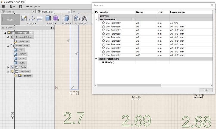
• Parametric design for pressfit.
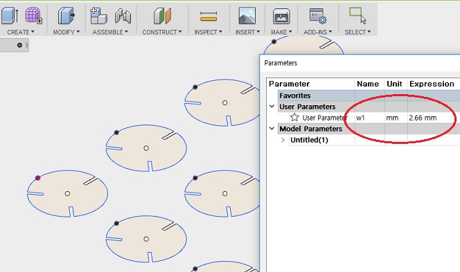
I made this job on Fusion360 for parametric change variable to take wright value
in experimental cuttings.
- file download : pressfit3.zip(dxf)
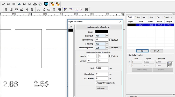
Experimentally find cutting parameters. These value are 75~80% of laser power and 15mm/s with 3mm thickness MDF plate.
• Experimental cutting to find best fit.
In this experiment, I found the best fit value is 2.66mm.
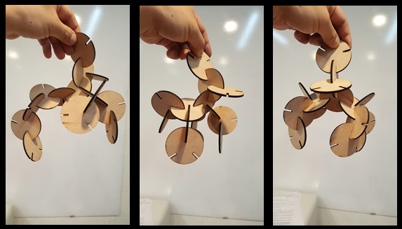
Step 3. Making a structure.
• Parametric design for the structure.
Now I can design for a structure with a fit value at 2.66 mm.
- file download : struct.dxf
• Cut and assembly.
Consideration about kerf for this project.
• The meaning of kerf = (measureed thickness - fit value) / 2
In calculation to take this :
The kerf = (3.05 - 2.66)mm / 2 = 0.195 mm
* This is as the lost unit distance for laser cutting as above conditions.