This week we had two assignments. The first one is individual assignment to add an output device to a microcontroller board you’ve designed, and program it to do something
My goal for this week is to finish the board with IR and servo motor.
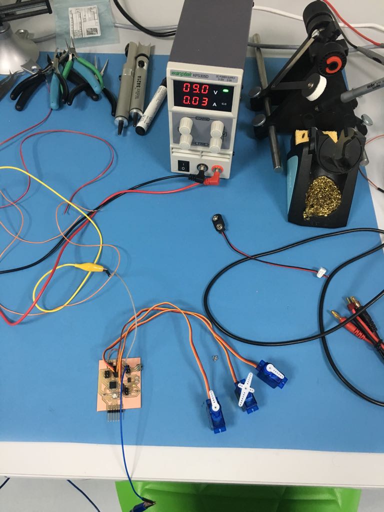
I companied this week with the previous week. So the board have one input device which is IR sensor and one output which is micro servo motor. In this week I will document I did regarding the servo.
First why I chose the servo motor? I chose it because in my final project I will need three motors. So I want now to know what is servo motor and how it work.
After reading about servo motor I knew that its four things compine togther which are DC motorwhich convert direct current energy into mechanical energy, gear reduction unit that reduce the speed to low RPM range require, The servo motor is actually an assembly of four things: a normal DC motor, a gear reduction unit, a position-sensing device (usually a potentiometer—a volume control knob), and a control circuit.
I talked about the design in week 11. I chose 2x3 header to connected with the servo. I though of puting FTDI but the problem that I must put it in the edge and this will couse alot of time in designing so I chose the header cause I can but it in anyplace. I conected the servo to pin2.
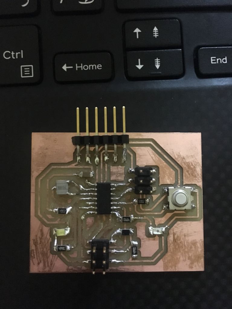
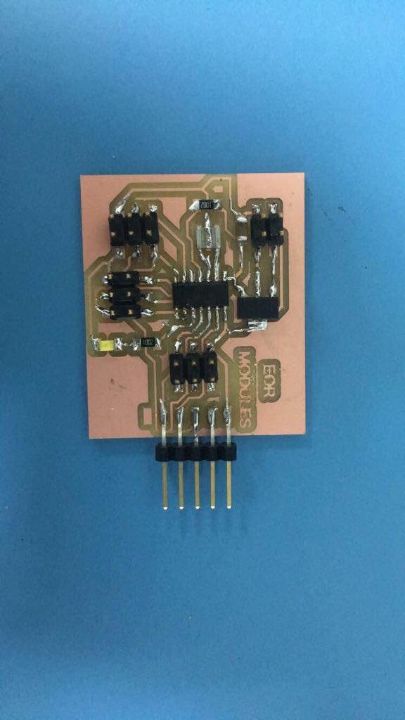
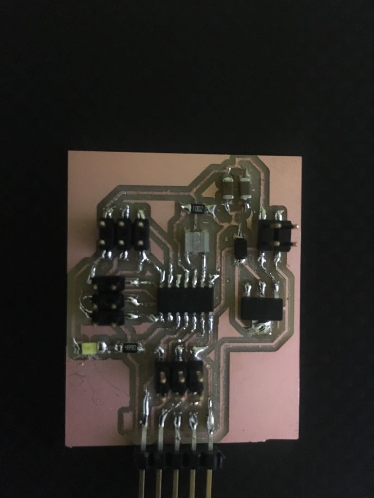
I finish soldering the board I didnt face any problems regarding the header.
In programing I searched on previuose student page to see if someone used servo I found Jiyoung An which used servo as an output on here output week. Her page helped me a lot.
The schematic and board of this week you will find it in week 11
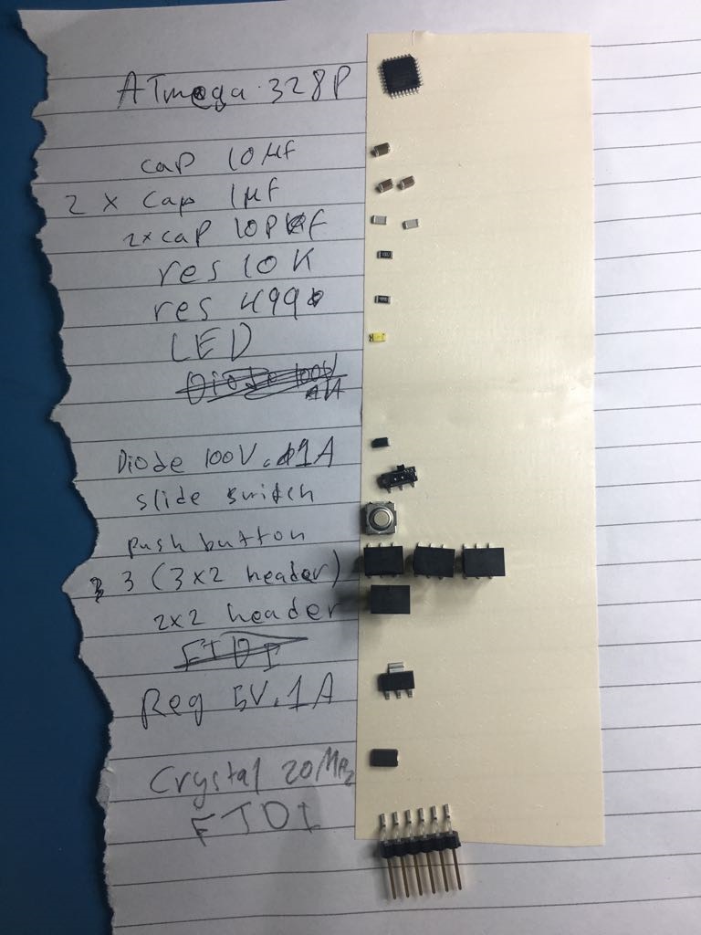
After thinking and searching I decided to make a board for three servos which I will use in my project. I asked Hashim about the three servos and he told me ATmega328P will be good for you. I spent time on the internet to learn more about it. I found here a tutorial to install the library of Atmega 328p on Arduino. After many tries, I failed to find a library of atmega238 for Eagle so Hashim put a link in the group for Sparkfun library which has Atmega328. After that, I decided not to go with atmega 328 instead using attiny44. There was no technical reason its just I started with attiny 44 and I want to work a lot with this microcontroller to learn a lot about it then I will use other microcontrollers.
I returned to Attiny44 and I used Neil pcb from output week.
I added 3x2 header for the third servo, Diode (100V,1A) for the regulator to not burn, regulator(5V,1A), and two capacitors with 10µf because we don't have 22µf in the fab(I connected the two capacitors in parallel to be 20µf).
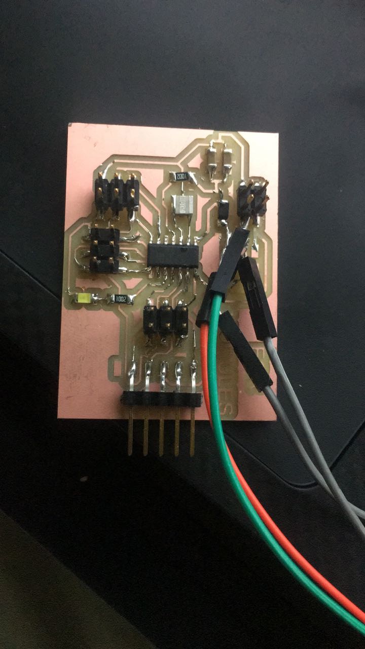
I faced some problems regarding the regulator I thought it must be connected like Niel did on his board. So I made the first PCB going through the same process I did in week 5,7,11 which are milling, soldering, visual inspection, and testing. When I plugged the FTDI in the PCB. The microcontroller became hot so immediately I removed the FTDI cable. I forget to connect the VCC of the FTDI to the 2x2 header. instead, I connect it to the microcontroller which is wrong because there will be no benefit from the regulator. So before redesigning I thought of using a battery instead of the FTDI to check if there are another problems. I changed the microcontroller and when I connect the battery the microcontroller became hot aagin.
After that I saw the datasheet of the regulator and with the help of Hashim I understand the connection of the regulator so I redesign my PCB again. Before I connect the pins of the regulator wrong, I connect the two pins out with GND and the pin IN to OUT and the pin ADJ to the battery. But now I learned the lesson I connect the pins correctly.
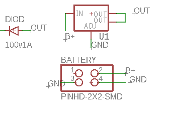
Then Hashim told me to see his page and I learned that I must connect a diode to protect the regulator from burning so I add it and finally, I'm done with this PCB.
Regarding the program I serched alot and I found alot of codes they all used attiny44 with servo but it didnt work with. So this is a massege for who wha
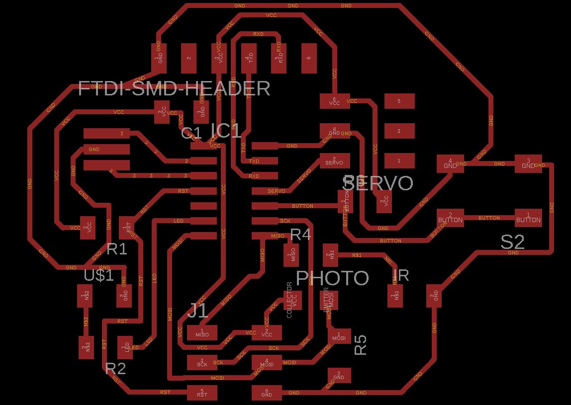
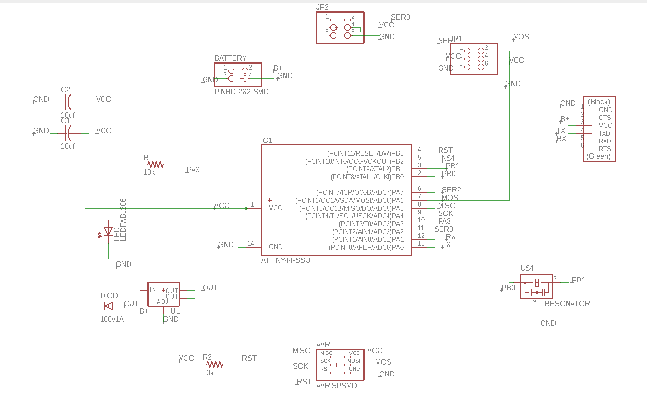
Here is the schematic
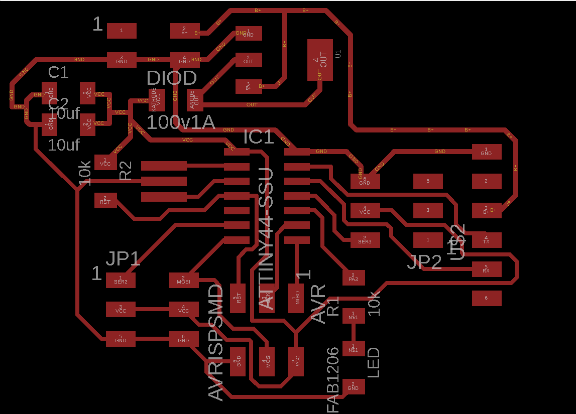
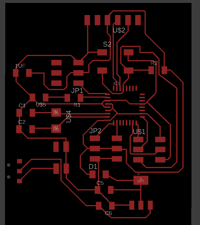
Here is the board
Here is the traces as png
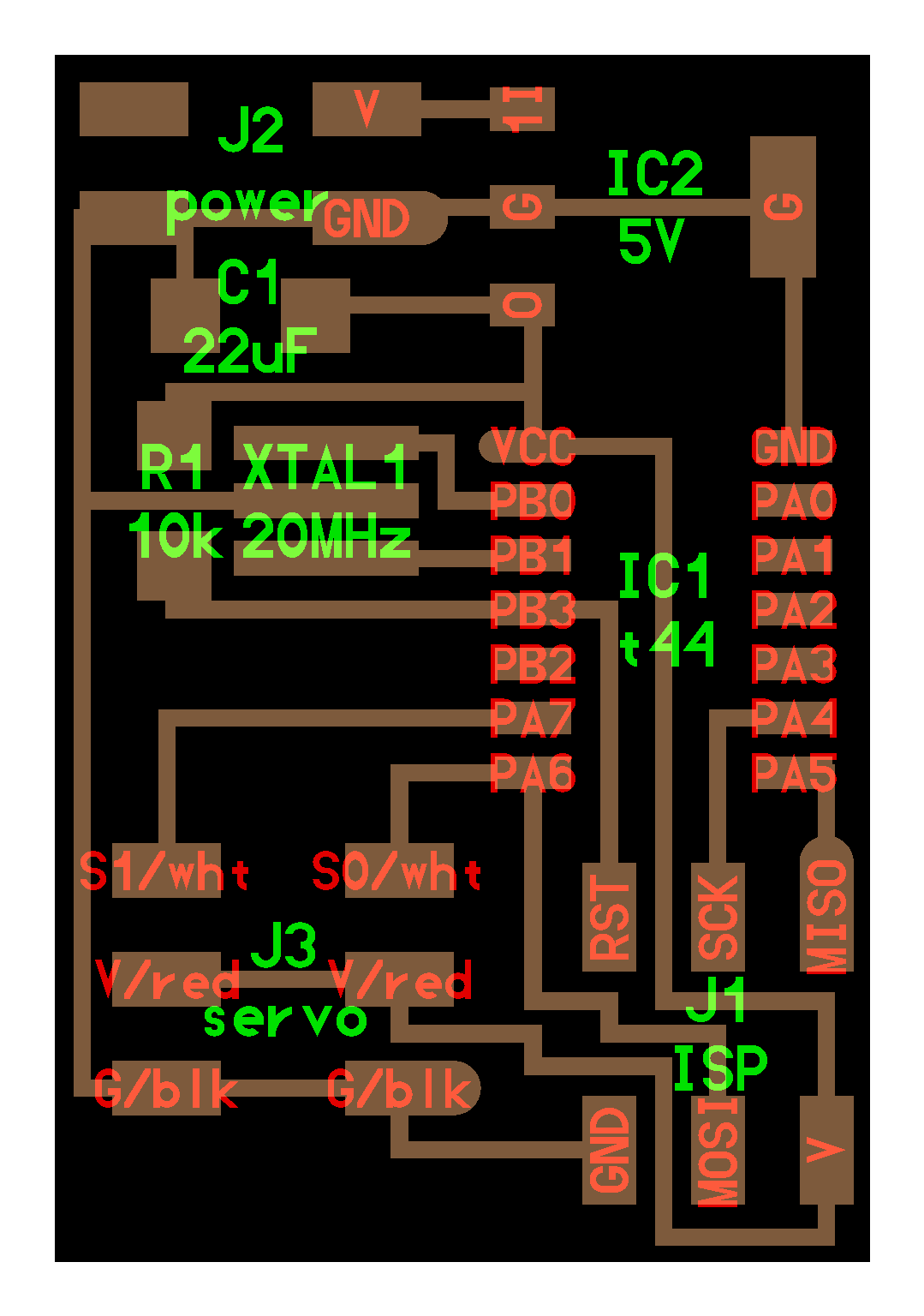
Here is the outline
I tried a lot to make the servo work but none of the codes helped I mean when the command is -move to angle 150- the servo move little and start shacking it's like the servo resist the command. The only code works is the one in ARDUINO page. When I download the servo library I found it so I try it and it works. The only difference between this code andb the others is that they use refresh and they didn't specify a number in ( servo.write). In the code, They define what are the limits and then they ask the servo to move between these limits and whenever it reaches one limit goes back. Then Hashim told me to take off the crystal because maybe the library work on 16 or 8 MHZ. I tried to read the library by opening it in NotePad++ and I found one part talking about 16Mhz I didn't understand what is written so I decided to take off the crystal. This will lead to changing the attiny44 because the current one is set it up to 20 MHz. So I will depend on 8 MHz because the attiny44 have it internally. I knew this from the datasheet. When I tried to take off the attiny44 I took some traces by mistake :). At that moment I decided to give up from attiny44 and move back to atmega328p and since Abdulla did the board and it was easy for him this gave me another reason to use it. I did the design with the help of Abdulla.
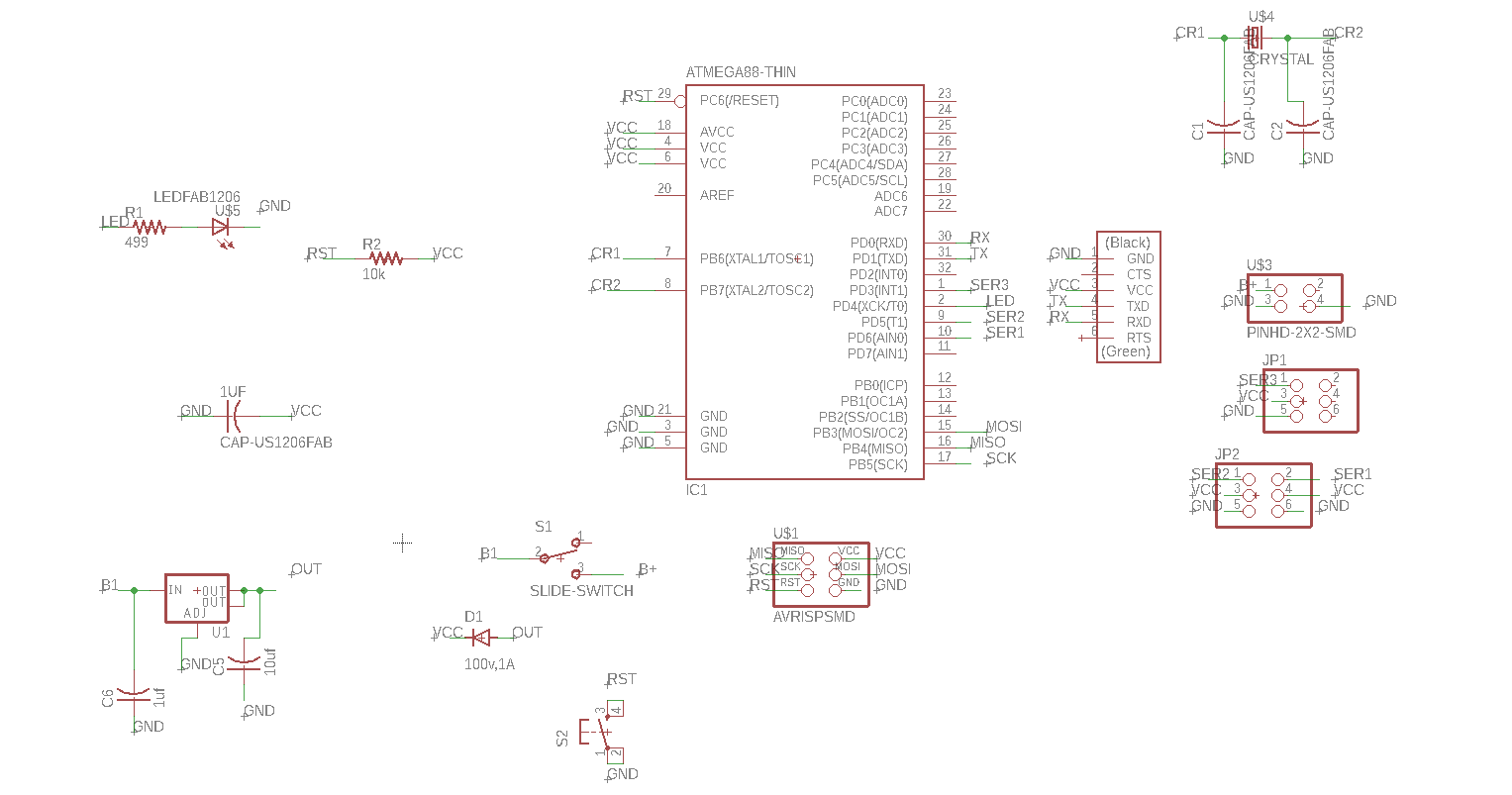
Here is the schematic
Here is the board
Here is the traces as png
Here is the outline
Here is the code
This week was the hardest week till know I searched a lot and a lot of time I got stuck. I can't imagine that I worked with attiny44 then I changed to Atmega328 then I return back to Attiny44 just to make this work. I really wanted this to work because it is very important to my final project. I learned many things from this assignment I'm very happy that I make it.
.png)
.png)
.png)
.png)