
Networking and communications
Assignments
- Group Assignment : Send a message between two projects
- Individual Assignment : Design and build a wired &/or wireless network connecting at least two processors
Introduction
In this week we should need to to network between atleast two microcontroller boards and comminicate etch other. In this week iam going to try some hardware loevel protocols to interconect more than two boards. But they are mainly categerised in to two types for inter-exchanging datas(Serial & Parellel). Also Wired and Wirless communication methods are available. In Wired communication, there are I2C, UART,SPI are the common type of methods that are using to make a network between the boards. I would like to both of them. There are a lot of Atleast i can try them. In wireless communication, commonly used, Bluetooth,WiFi,NFC,RF, Sub1GHZ etc... are the type of methods.
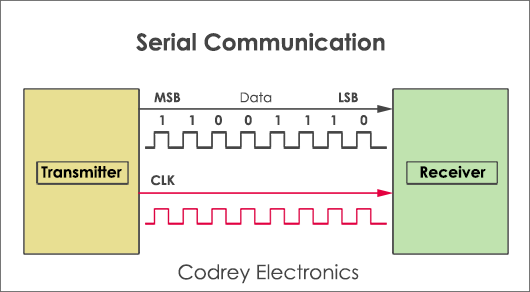
Serial communication
Simply, in serial communication we can send a Bit at a time. So it should be the process of sending the Bit at a time continuesly. It is only need two wire when comparing with parellel communications. A bit will transmit or receive for every clock pulse.
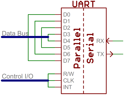
UART(Universal Asynchronous Receiver/Transmitter)
The final piece to this serial puzzle is finding something to both create the serial packets and control those physical hardware lines. Enter the UART. A universal asynchronous receiver/transmitter (UART) is a block of circuitry responsible for implementing serial communication. Essentially, the UART acts as an intermediary between parallel and serial interfaces. On one end of the UART is a bus of eight-or-so data lines (plus some control pins), on the other is the two serial wires - RX and TX.
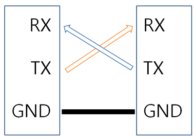
UARTs do exist as stand-alone ICs, but they’re more commonly found inside microcontrollers. You’ll have to check your microcontroller’s datasheet to see if it has any UARTs. Some have none, some have one, some have many. For example, the Arduino Uno - based on the “old faithful” ATmega328 - has just a single UART, while the Arduino Mega - built on an ATmega2560 - has a whopping four UARTs. As the R and T in the acronym dictate, UARTs are responsible for both sending and receiving serial data. On the transmit side, a UART must create the data packet - appending sync and parity bits - and send that packet out the TX line with precise timing (according to the set baud rate). On the receive end, the UART has to sample the RX line at rates according to the expected baud rate, pick out the sync bits, and spit out the data. Here is the conection between the device.
I2C communication
I used I2C communication before for interfacing some modules witrh arduino development boards. As i mentioned earlier, i choosed I2C communication to do the assignment this week. I would like to know more about I2C communication. So what is i2C communication? The Inter-integrated Circuit (I2C) Protocol is a protocol intended to allow multiple slave digital integrated circuits (chips) to communicate with one or more master chips. Like the Serial Peripheral Interface (SPI), it is only intended for short distance communications within a single device. Like Asynchronous Serial Interfaces (such as RS-232 or UARTs), it only requires two signal wires to exchange information. I2C requires a mere two wires, like asynchronous serial, but those two wires can support up to 1008 slave devices. Also, unlike SPI, I2C can support a multi-master system, allowing more than one master to communicate with all devices on the bus (although the master devices can’t talk to each other over the bus and must take turns using the bus lines). Data rates fall between asynchronous serial and SPI most I2C devices can communicate at 100kHz or 400kHz. There is some overhead with I2C for every 8 bits of data to be sent, one extra bit of meta data must be transmitted. The hardware required to implement I2C is more complex than SPI, but less than asynchronous serial. It can be fairly trivially implemented in software.
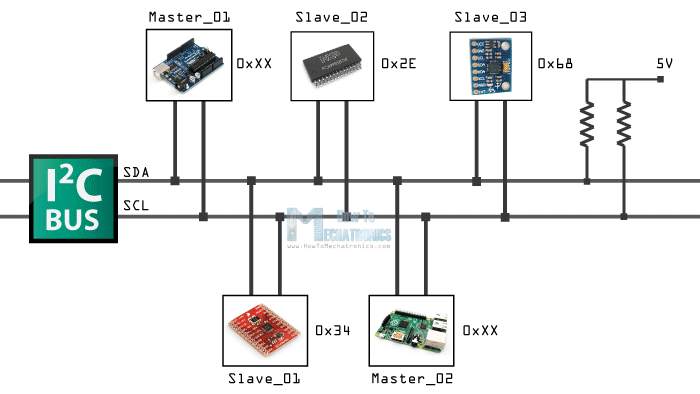
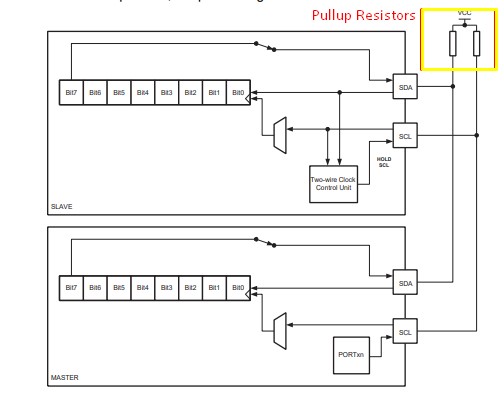
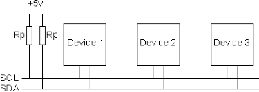
Pull up resistors for I2C Bus lines
Both SCL and SDA lines are open drain drivers. wich means that the chip can drive its output as low, but it cannot be drive it as high. For the line to be able to go high you must provide pullup resistors to the power supply. Usually ued a 10K resitor value for pullup up the SDA and SCL lines.
PCB designing and milling
We got much infirmations about I2C. Now lets built some PCBs to communicate each other through I2C bus.
MOSI and
SCK are I2c pins. So i think
i can reuse Previous Boards, which i used in Input week
The master board is consist of a Button and LED and slave board have a single LED only.
So when i press the button on Master board, the LED on the slave board as well as LED on the
master board will glow.
SO that is my plan. Now lets start coding. In tis time i think i need to make a pullup resistance
in I2C. So i designed
a board withicsp pin headers and Pullup resistors
Download proteus PCB designs
PCB LAYOUT

After Soldering
This board is only for pullup, its have 2 resistors. one pullup for both SDA and SCL. so if we attach this to an i2c chanel, both SDA and SCL channel will be pullup.
I use some previous board
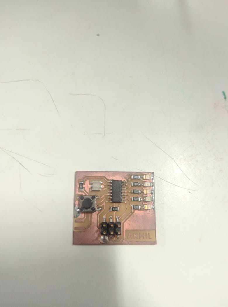
This board i used for embedded programing week, it have 1 switch in digital pin 8. and have 5 LEDs on pin 0,1,2,3,4 2 blue leds and 3 red leds. i use this as master board. heare we use master send slave recive mode. so no address is assigned for master board.
Download proteus PCB designs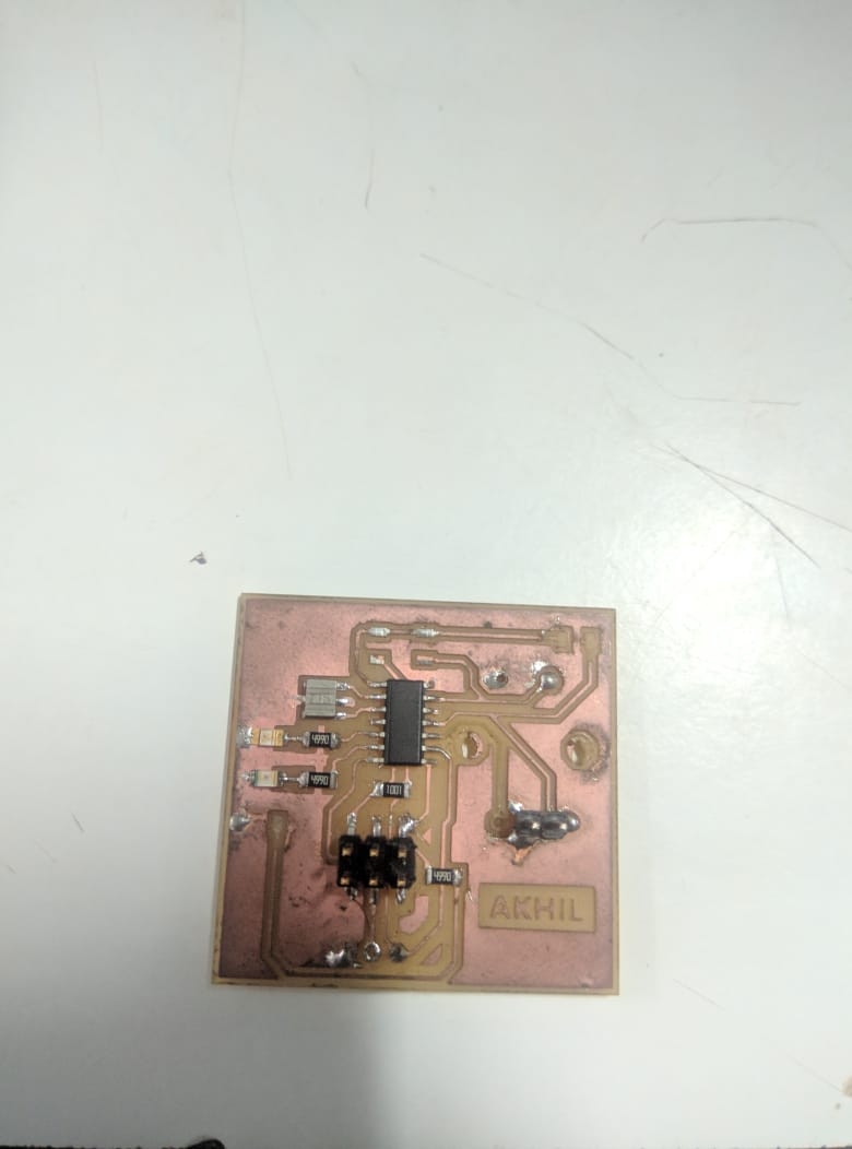
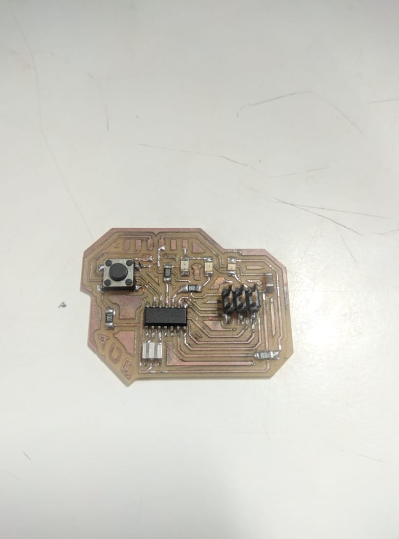
This board i pland for input week, this have a Rotary encoder footprint and 2 LED but the encoder circuit is a failer so
i designed another board for my input week.This board i configured as slave 1 with address 0x01
I2C_SLAVE_ADDR (0x01) by this code
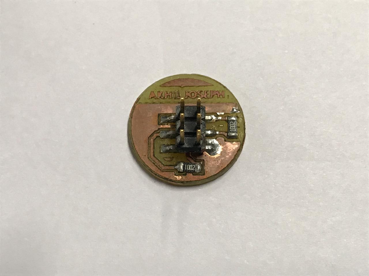
This board is designed by another student in our LAB, Akhil G babu
please reffer his page for more detailes and source files.This board i configured as slave 2 with address 0x02
I2C_SLAVE_ADDR (0x02) by this code
Embedded Programing
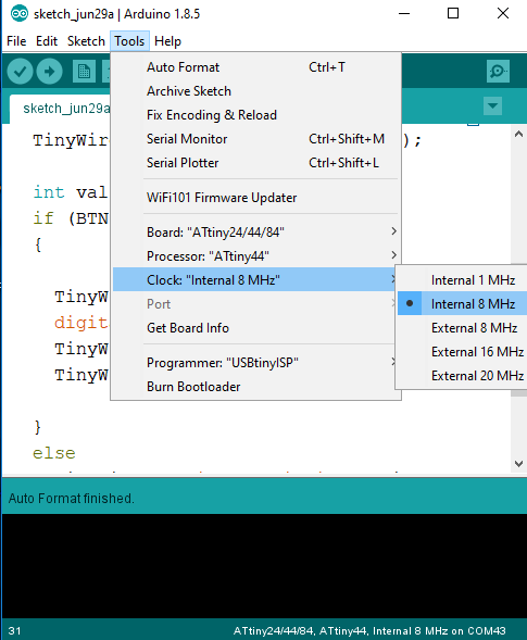
First i tried the Wire.h library that official given by the Arduino. But when compailing the wire.h library i got some error. So i googled and saw some answers from arduino forum that wire.h library wont work with attiny45 microcontrollers. As i xpected it happened. So now, i need to find another way. I searched for alternative arduino libaries that especially build for attiny microcontrollers. I found TinyWire.h library for arduino. The TinyWire.h library is build a for attiny microcontrollers. The library almost replicate the wire.h but stil i face some problems, so i try to edit library files. we edit somvalues in library. and i found that now its working with 8MHZ internal crystal. i use 20Mhz oscilator in my boards, its not working in that frequency range. i dont know why?
Programing Master board
    #include <PinButton.h>
    #include <TinyWireM.h>
    #define device (1)
    #define device2 (2)
    PinButton myButton(8);
    #define LED 1
    #define LED2 2

    void setup() {
      pinMode(BTN, INPUT);
      pinMode(LED, OUTPUT);
      pinMode(LED2, OUTPUT);
      TinyWireM.begin();

    }
    void loop() {
      myButton.update();
      if (myButton.isSingleClick()) {
        TinyWireM.beginTransmission(device);
        digitalWrite(LED, HIGH);
        TinyWireM.send(1);
        TinyWireM.endTransmission();
      }
      else
      {
        TinyWireM.beginTransmission(device);
        digitalWrite(LED, LOW);
        TinyWireM.send(0);
        TinyWireM.endTransmission();
      }
      if (myButton.isDoubleClick()) {
        TinyWireM.beginTransmission(device2); //device 2
        digitalWrite(LED2, HIGH);
        TinyWireM.send(1);
        TinyWireM.endTransmission();
      }
      else{
         TinyWireM.beginTransmission(device2); // device 2
        digitalWrite(LED2, LOW);
        TinyWireM.send(0);
        TinyWireM.endTransmission();
      }
    }
Testing with 2 boards
Programing Slave board
                                    #include <TinyWireS.h>
                                    #define LED 3
                                    #define I2C_SLAVE_ADDR (1)
                                    void setup() {

                                    TinyWireS.begin(I2C_SLAVE_ADDR);
                                    pinMode(LED, OUTPUT);
                                    }

                                    void loop() {
                                    if (TinyWireS.available())
                                    byte data = TinyWireS.receive();
                                    if (data == 1)
                                    digitalWrite(LED, HIGH);
                                    else if (data == 0)
                                    digitalWrite(LED, LOW);

                                    }
Download Arduino code Download Arduino Library (edited)
Working demo
Group work
My friend Joel Make a Wi-Fi board using ESP8266. So i would like to make somthing interesting. Full PCB files Avialable in his page
Programing ESP8266 Alexa
                                                                    #include <ESP8266WiFi.h>

                                      #include "WemoSwitch.h"
                                      #include "WemoManager.h"
                                      #include "CallbackFunction.h"

                                      boolean connectWifi();

                                      void lightOn();
                                      void lightOff();
                                      void secondOn();
                                      void secondOff();
                                      char ssid[] = "Wi-Fi Username";
                                      char password[] = "Wi-Fi Password";
                                      WemoManager wemoManager;
                                      WemoSwitch *light = NULL;
                                      const int ledPin = 13;
                                      void setup()
                                      {
                                        Serial.begin(115200);
                                        WiFi.mode(WIFI_STA);
                                        WiFi.disconnect();
                                        delay(100);
                                        Serial.print("Connecting Wifi: ");
                                        Serial.println(ssid);
                                        WiFi.begin(ssid, password);
                                        while (WiFi.status() != WL_CONNECTED) {
                                          Serial.print(".");
                                          delay(500);
                                        }
                                        Serial.println("");
                                        Serial.println("WiFi connected");
                                        Serial.println("IP address: ");
                                        IPAddress ip = WiFi.localIP();
                                        Serial.println(ip);
                                        wemoManager.begin();
                                        light = new WemoSwitch("light", 80, lightOn, lightOff);
                                        wemoManager.addDevice(*light);
                                        pinMode(ledPin, OUTPUT);
                                        delay(10);
                                        digitalWrite(ledPin, HIGH);
                                      }
                                      void loop()
                                      {
                                        wemoManager.serverLoop();
                                      }
                                      void lightOn() {
                                          Serial.print("Switch 1 turn on ...");
                                          digitalWrite(ledPin, HIGH);
                                      }
                                      void lightOff() {
                                          Serial.print("Switch 1 turn off ...");
                                          digitalWrite(ledPin, LOW);
                                      }