5. Electronics production
Assignment
1 ,Make an in-circuit programmer by milling the PCB
2, Optionally, trying other processes
Make and Program an ISP Programer
I have some previous experience in PCB manufacturing using etching process .This is the first time i am using a milling machine for pcb manufacturing.So i am realy excited to experienced this opportunity.
In System Programming
In-system programming (ISP), also called In-Circuit Serial Programming (ICSP), is the ability of some programmable logic devices, microcontrollers, and other embedded devices to be programmed while installed in a complete system, rather than requiring the chip to be programmed prior to installing it into the system.-wiki
Let’s start
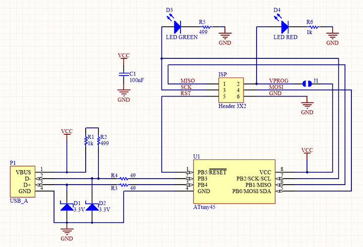
FabISP is an in-system programmer for AVR microcontrollers. There are different versions of ISP’s available in the archieve. I selected Brians Version of Fab ISP called “FabTinyISP”.
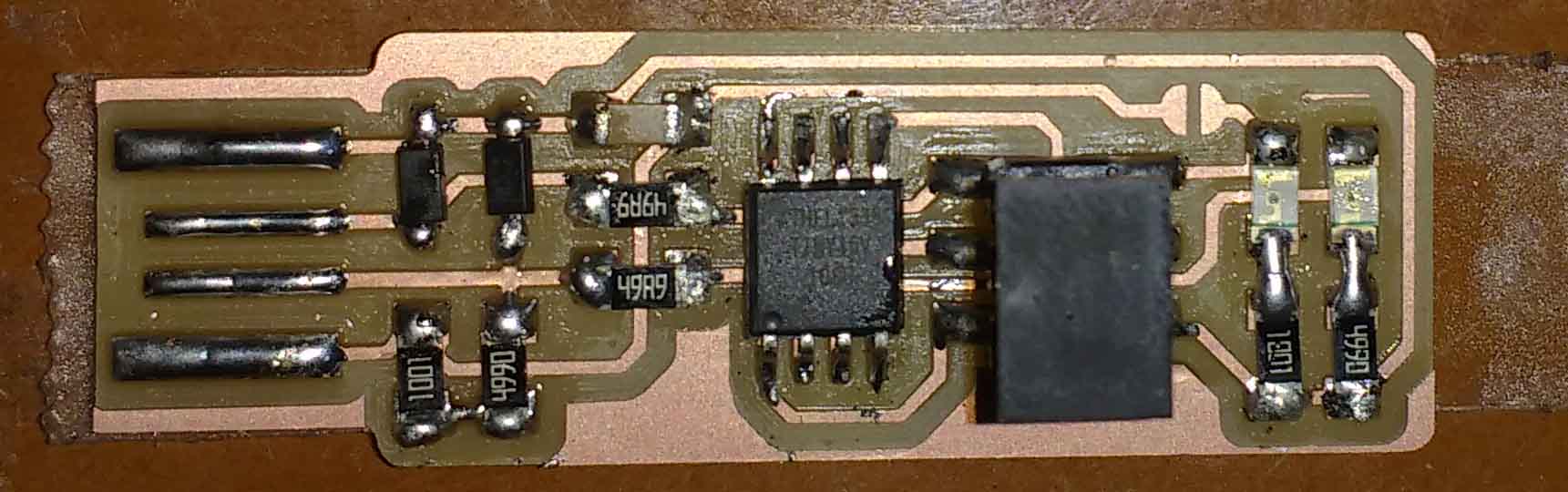
FabTinyISp It is a ATtiny45 based board having high-performance, low-power Atmel 8-bit AVR RISC-based microcontroller combines 4KB ISP flash memory, 256-Byte EEPROM, 256B SRAM, 6 general purpose I/O lines, 32 general purpose working registers, one 8-bit timer/counter with compare modes, one 8-bit high speed timer/counter, USI, internal and external Interrupts, 4-channel 10-bit A/D converter, programmable watchdog timer with internal oscillator, three software selectable power saving modes, and debugWIRE for on-chip debugging. The device achieves a throughput of 20 MIPS at 20 MHz and operates between 2.7 - 5.5 volts.I choose Brian’s verson because this design doesn’t have any clock circuits and additional LED’s are there to indicating the status of the board while programming.
Schematic
Position Diagram
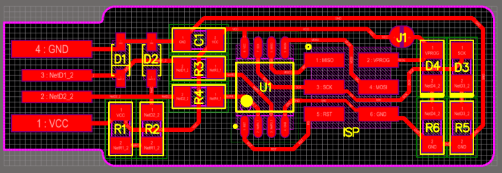
Layout
milling traces
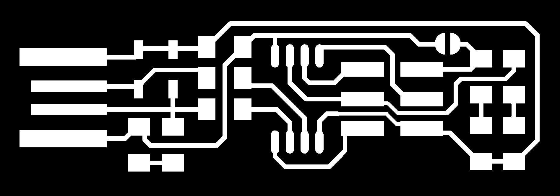 Milling traces

Modela MDX20 Machine
For milling the circuit I used a Roland MDX-20. The Modela MDX20 is a Desktop 3D scanning and Milling machine by Roland. Easy to use,Compatiable with popular softwares, Powerfull and can directly connect to our compuetr via RS232C cable.
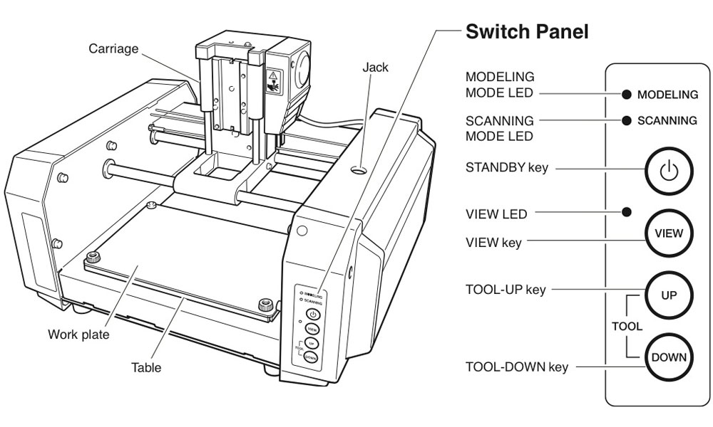
Work area 203.2 x 152.4 mm Z stroke 60.5 mm Spindle speed 6500 rpm
Milling work is divided into two phases: $ milling the PCB traces $ milling the out line For each of these phases we have to use a different mill drill bit and different settings. We use the fab modules to give commands to the Modella and run the cutting program. This machine is very delicate and the bits are very fragile, take care in removing the milling cutters and correcting the zero setting.
Cut with the Modella MDX 20
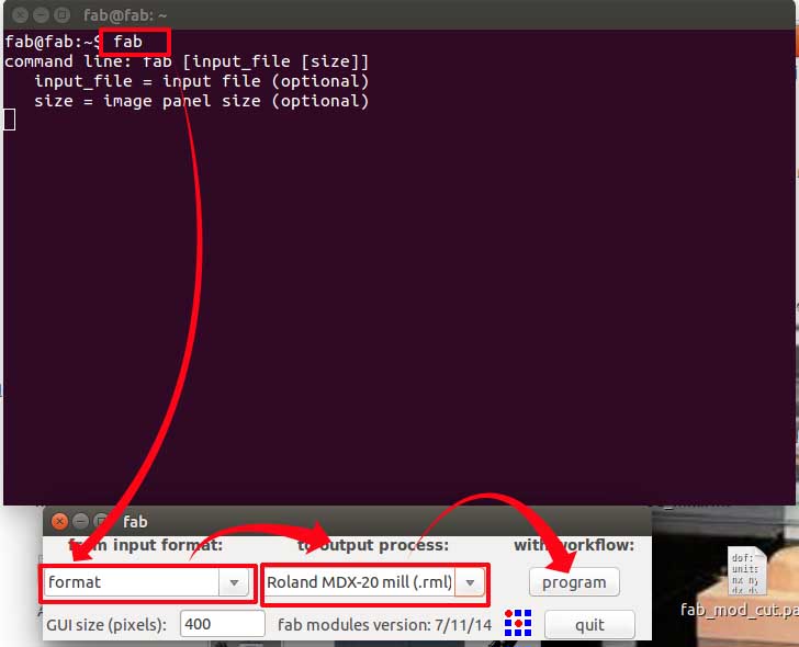
Modella MDX 20 is just like any other CNC mechine. We use the same fab modules which we used in vinyle cutting for milling also. The fab module converts the .png image we give into a series of tool paths, these tool paths are defined by their coordinates. The .png image is a black and white layout of the board, and the black portions will be milled and the white portion is where the copper will be left. Innorder to complete the PCB manufacturing process we have to do 2 process Tracing-Here we trace out all the circuit paths .For milling traces, we use the 1/64th inch (0.4mm) bit Cutting-Here we seperate the functional part of the pcb fram unwanted ares.for cutting we use 1/32th (0.8mm) inch bit. Got to the terminal and run fab Now the fab module will open and the select the input format to .png and select the output you want depending on your machine (modlella MDX 20).
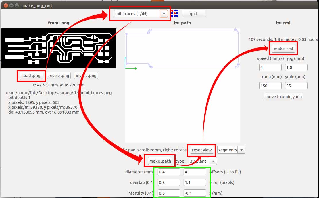
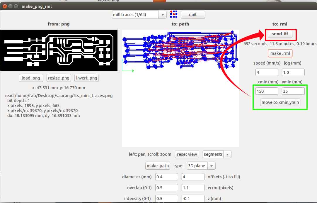
On the top menu select the process you want to use. For milling traces, select the milltraces(1/64) option. Now click load .png to load your traces file and click make path Now you can see the path the tool is going to move through. You can change the setting, I’m leaving it in the defaults. Now if you click make.rml and click send rml
Setting up the machine
 1st we were suppose to prepare the sacrifical layer.But we already had a sacrifical layer .So I decided to go with it.
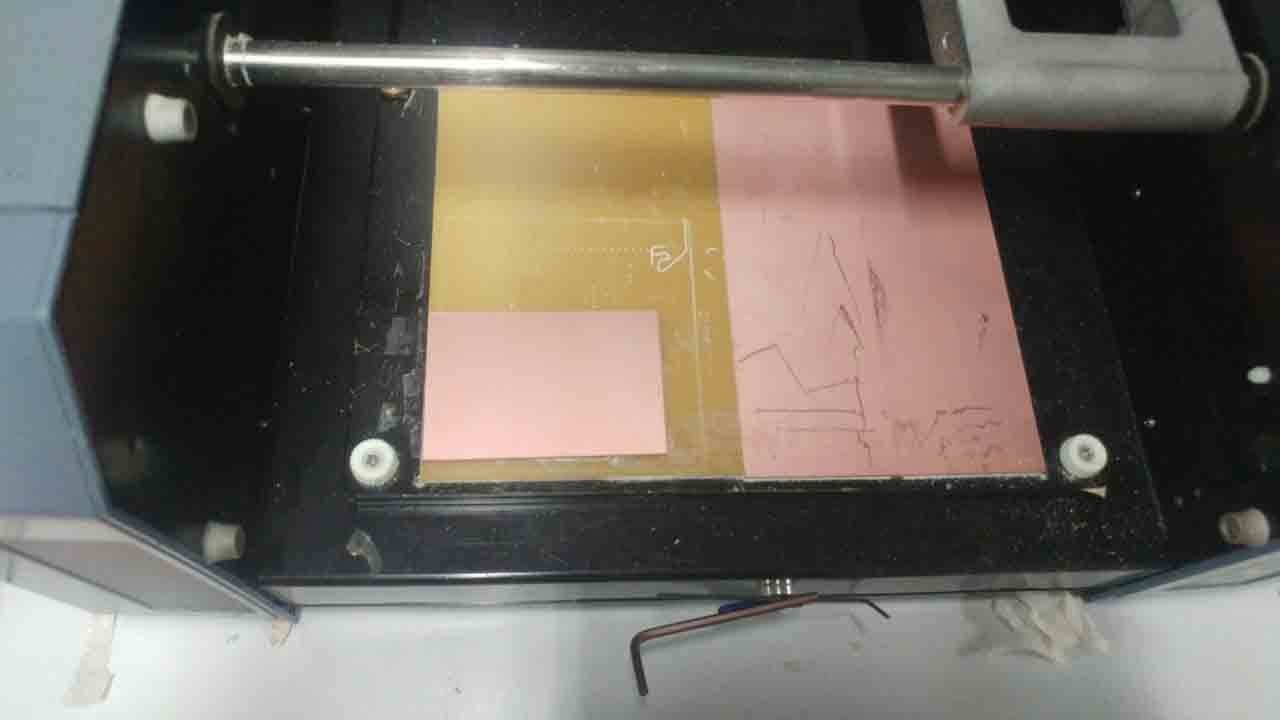 Next clean the PCB and Fix it to the CNC sacrifical layer with a double side tapes.Please make sure that the whole milling portion of the pcb is fixed to the table with the tape .If not the pcb may miss aline and may damage the cutting bit or the pcb itself.
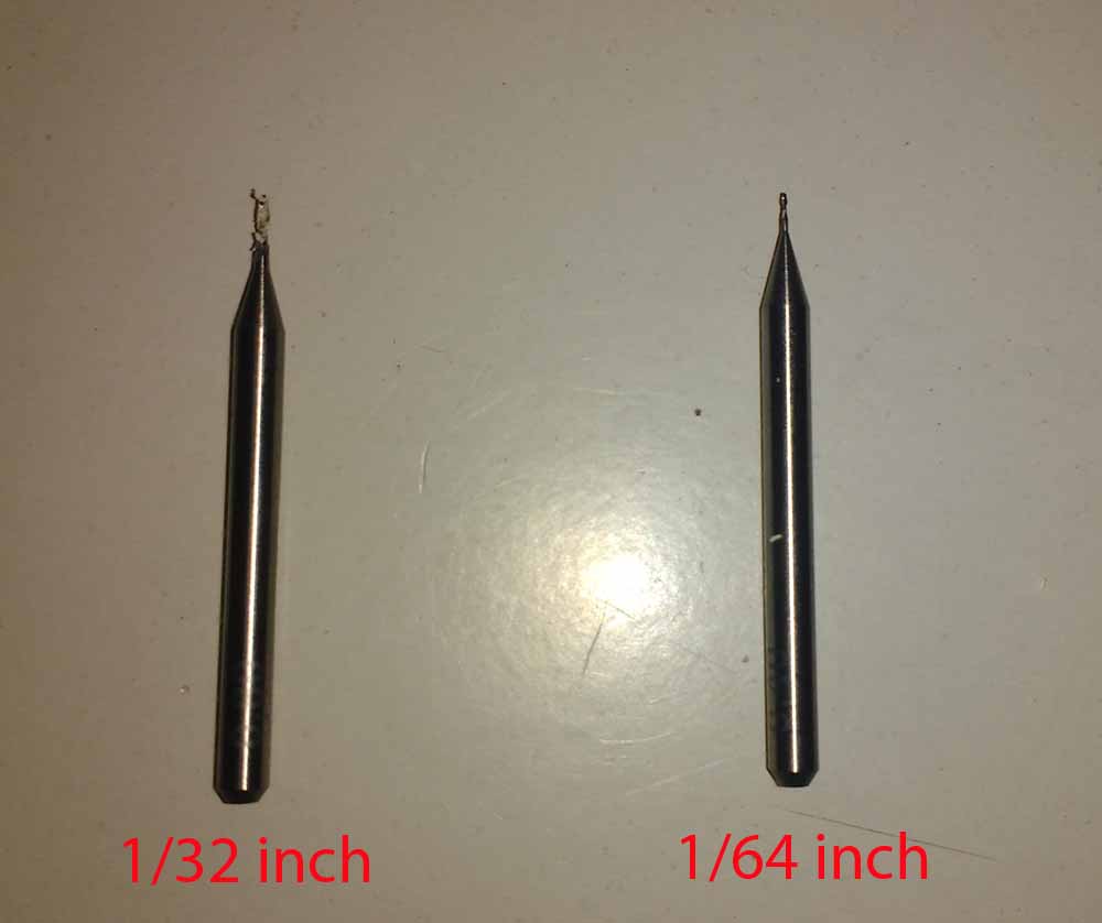
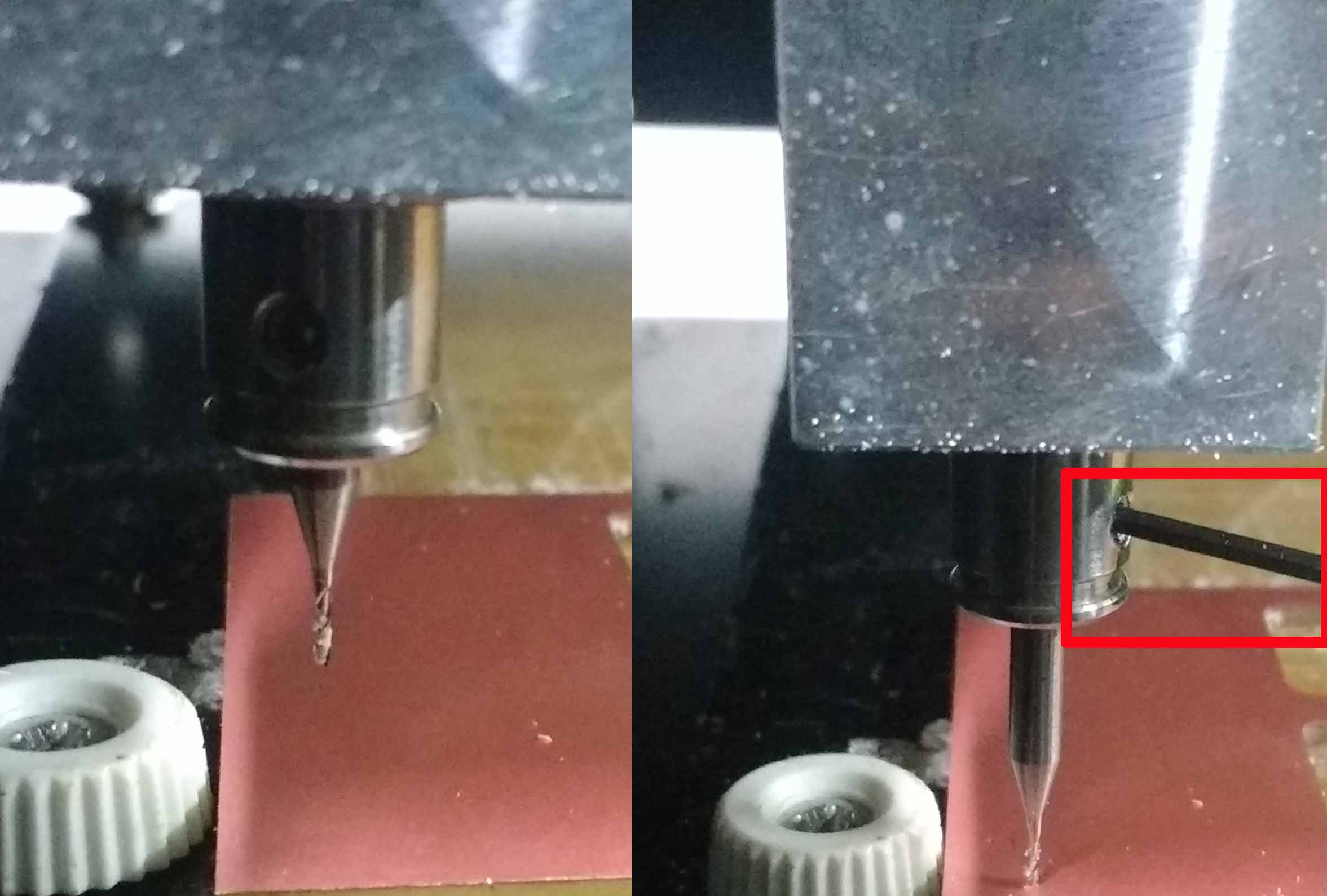
The 1/64 inch is used for tracing and 1/32 inch bit is used for cutting
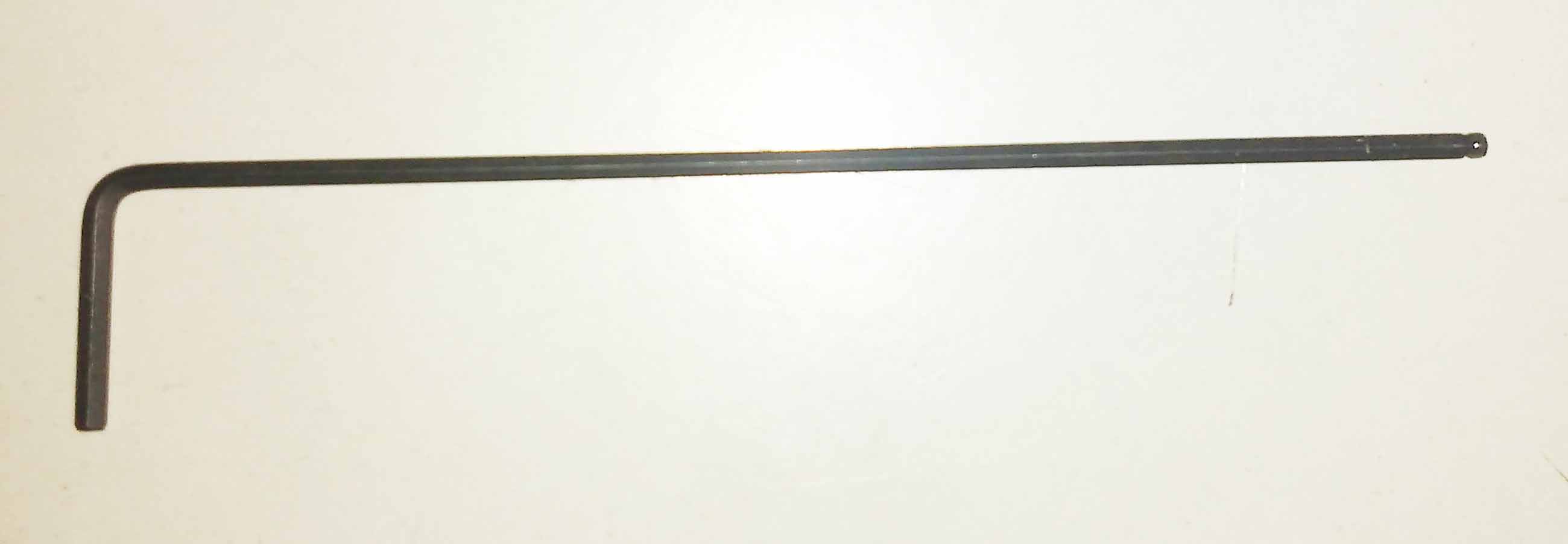
An L-key is used for releasing the bit from the chuck
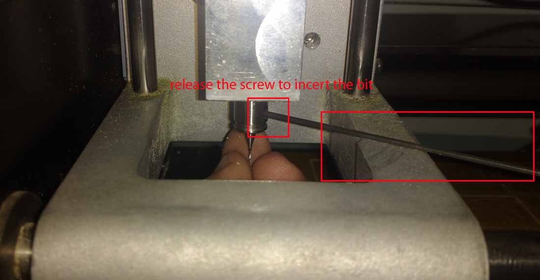
To set the Z-value correctly , we can use multiple ways but the most efficient and easiest way i found is Raise the Z axis to the top Release the chuck using the L-key Insert the 1/64 inch milling bit a little more in to the chuck tight the screw Down the z axis close as possible to the bed Unscrew the chuck and release the bit Slightly press the bit close to the bed and tight the chuck screw Done
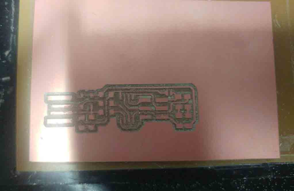
Complete the tracing process by sending it in to the milling Machine
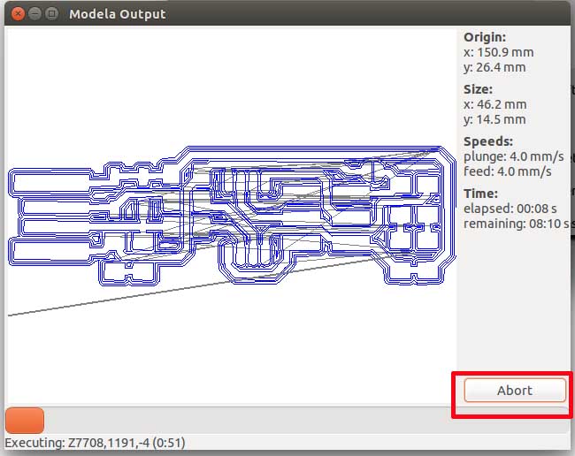
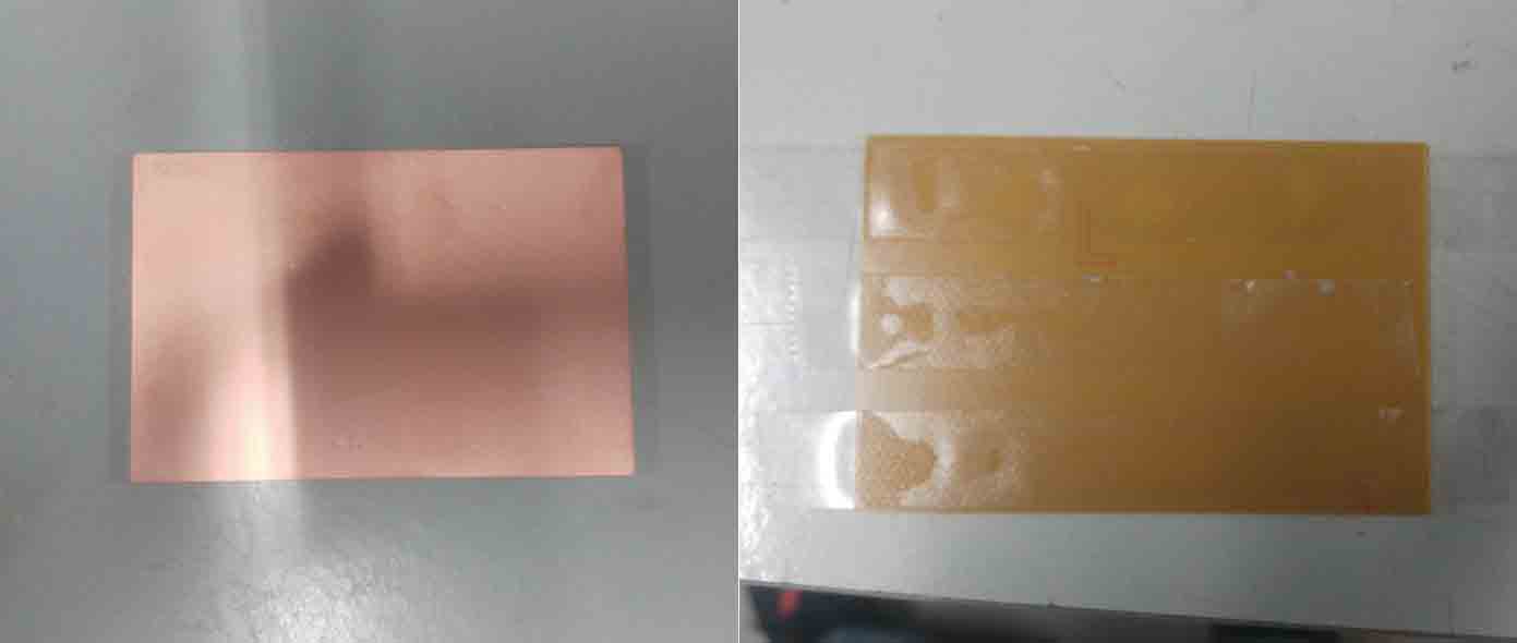
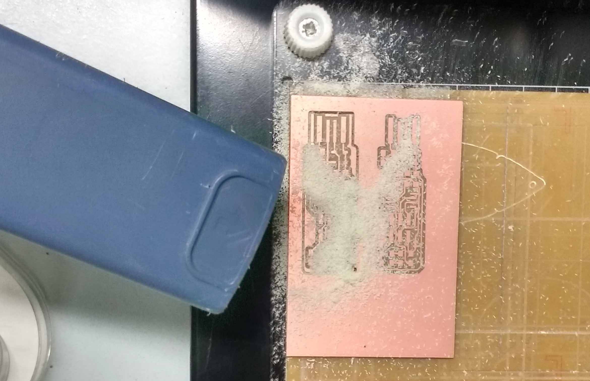
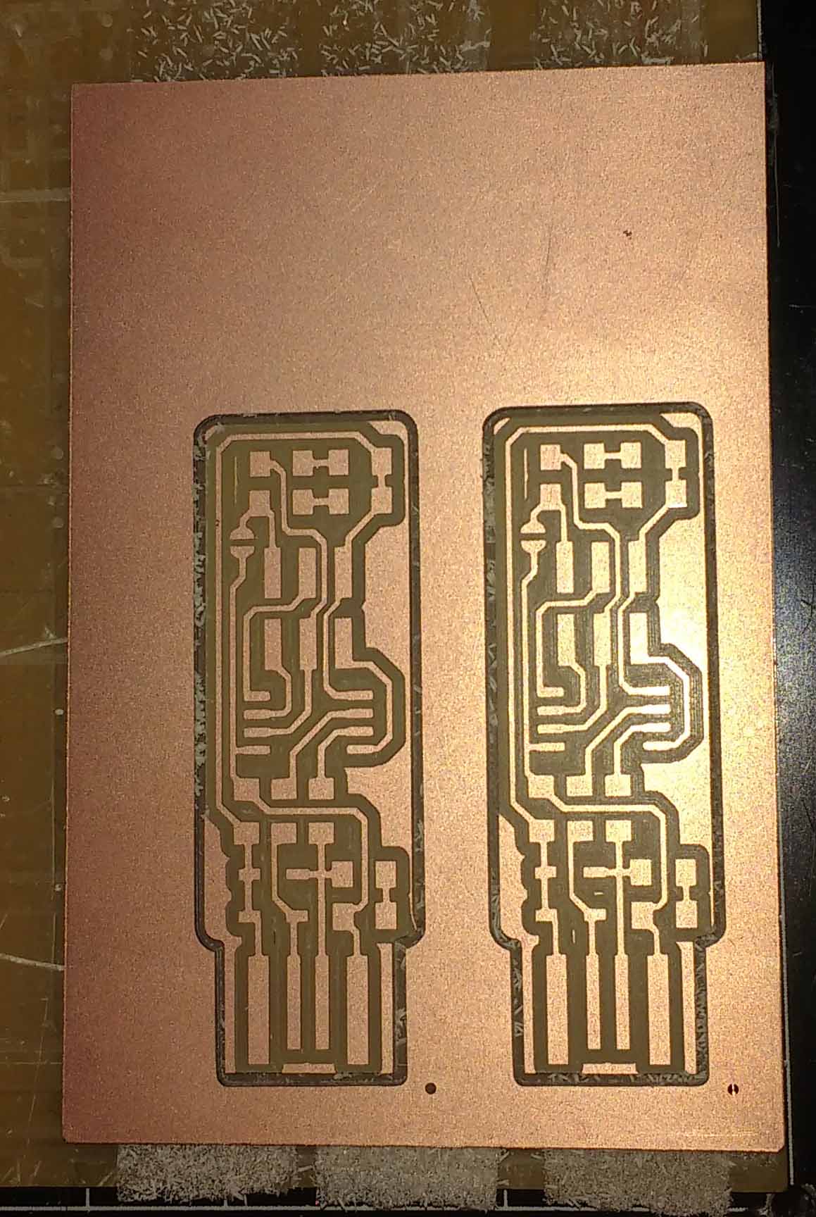
Incase we need to stope the process permanently we can use the abort button. If we wanted to stop the process for temporally we can use the view button on the modella. This is the PCB after completing traceing.
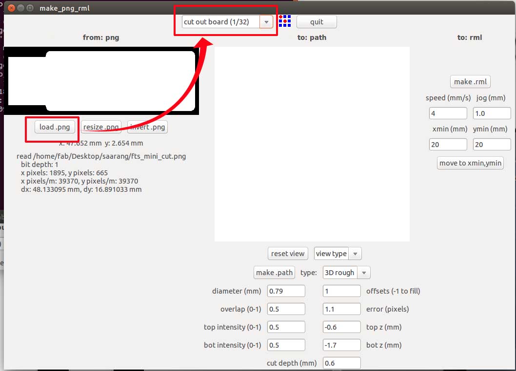
Load the cut file and change the bit to 1/32 . make the path and proced with milling after making the rml. Always be sure about not making a change in the origin.
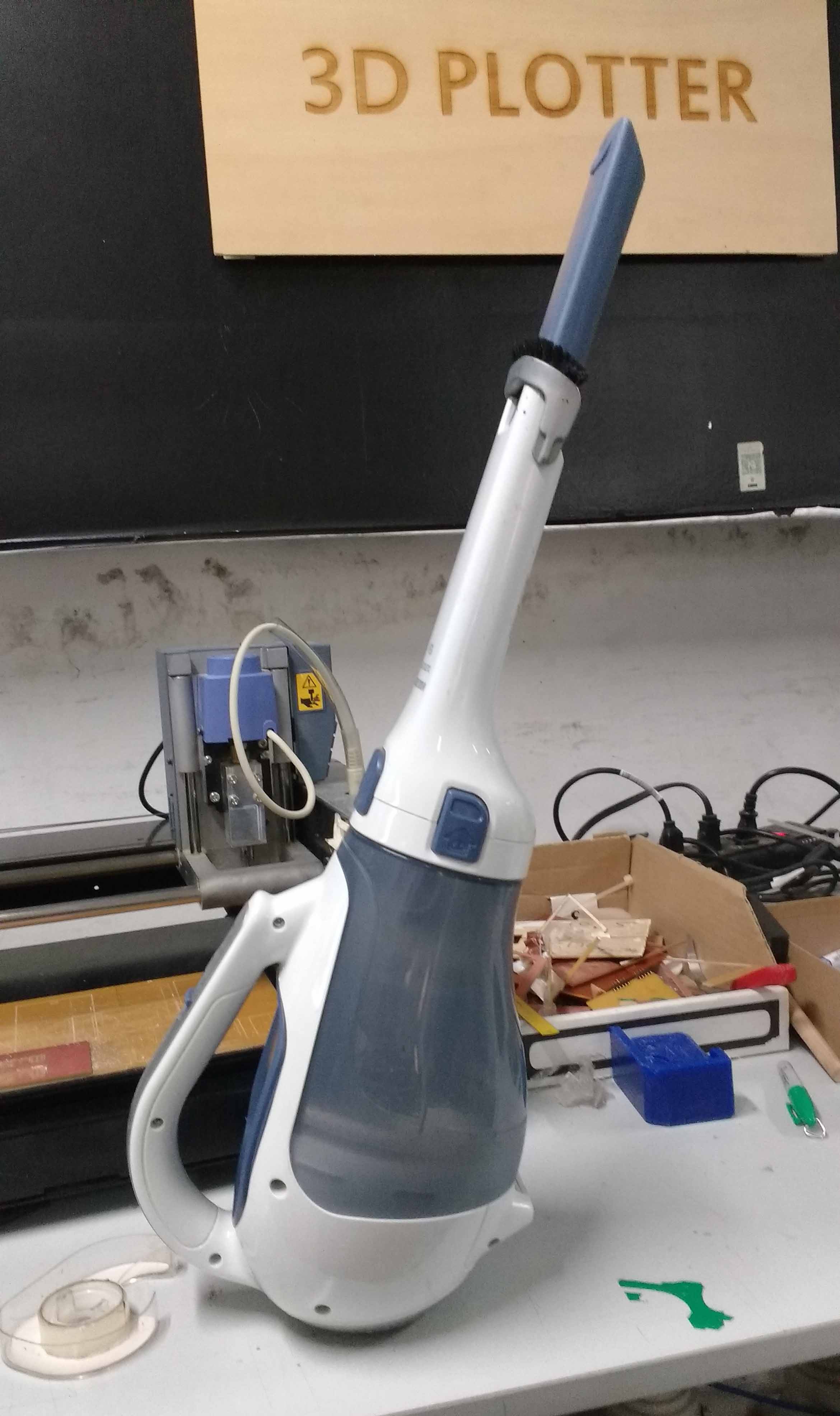
Clean the bed and the board with a vacuum cleaner after completing the millinging.
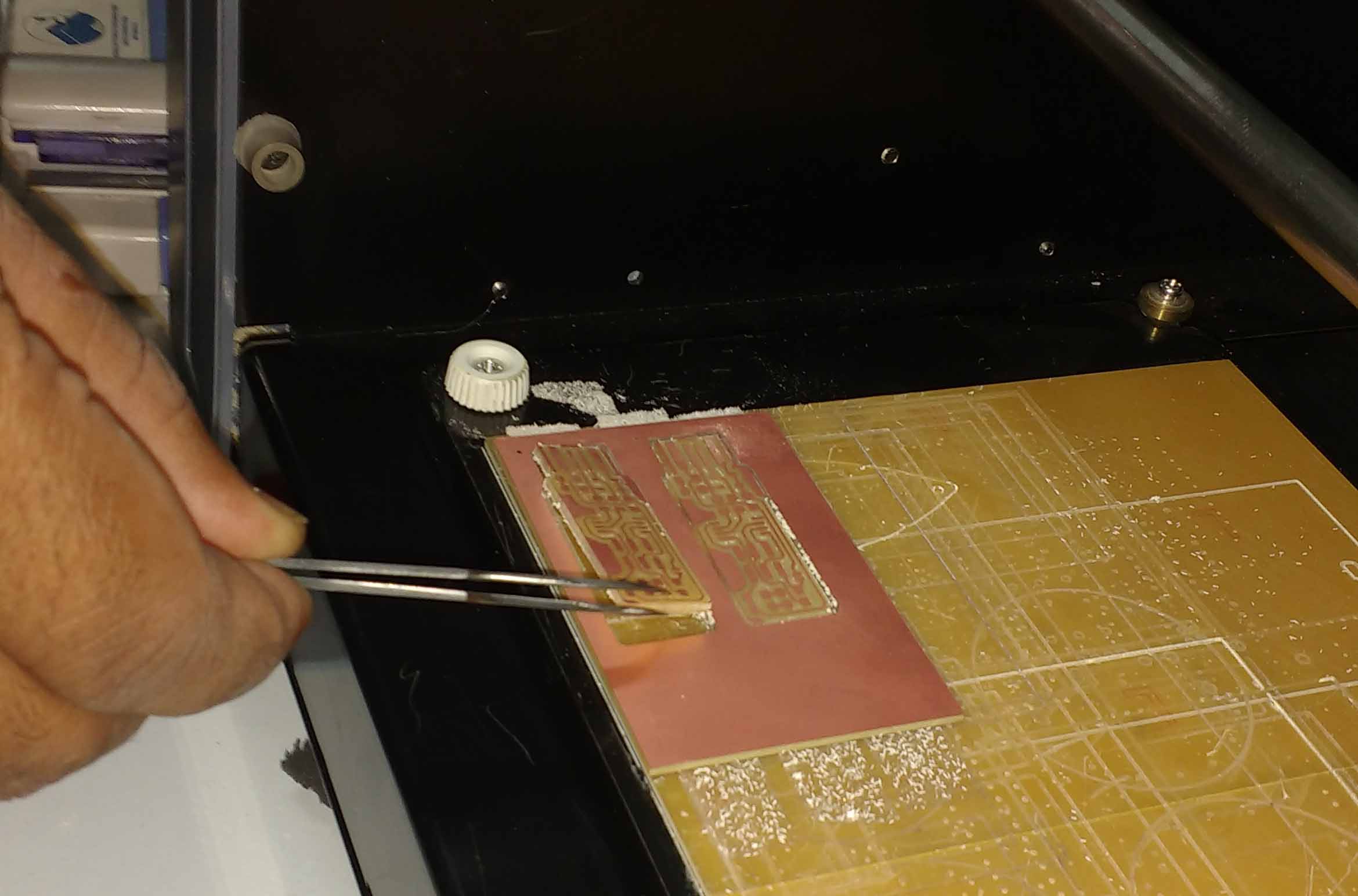
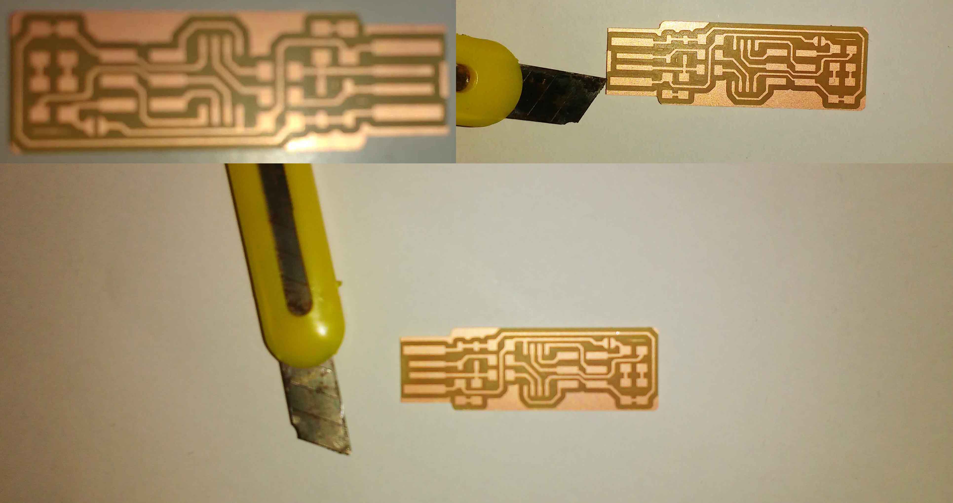
Remove the PCD carefully from the bed with a Tweezer or with the edge of a steel ruler.
soldering
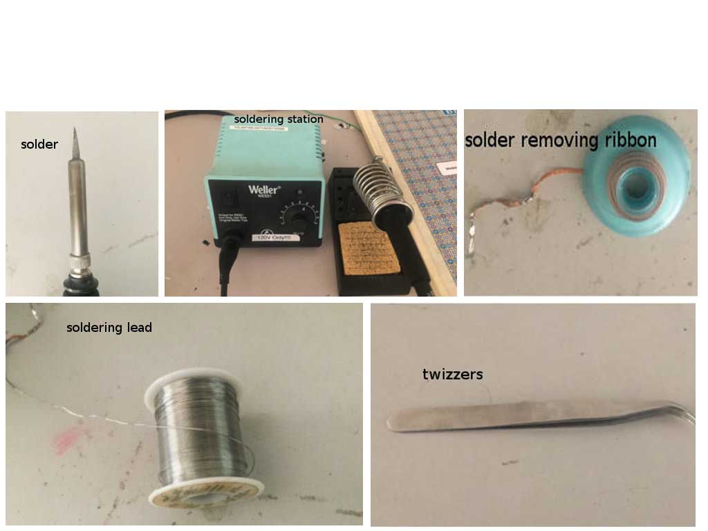
I have some previous experiences with through hole soldering .So I hope it won’t be much harder for me to completing my soldering. Before we start soldering make sure all the required instruments are available in our desk
I have some previous experiences with through hole soldering .So I hope it won’t be much harder for me to completing my soldering. Before we start soldering make sure all the required instruments are available in our desk
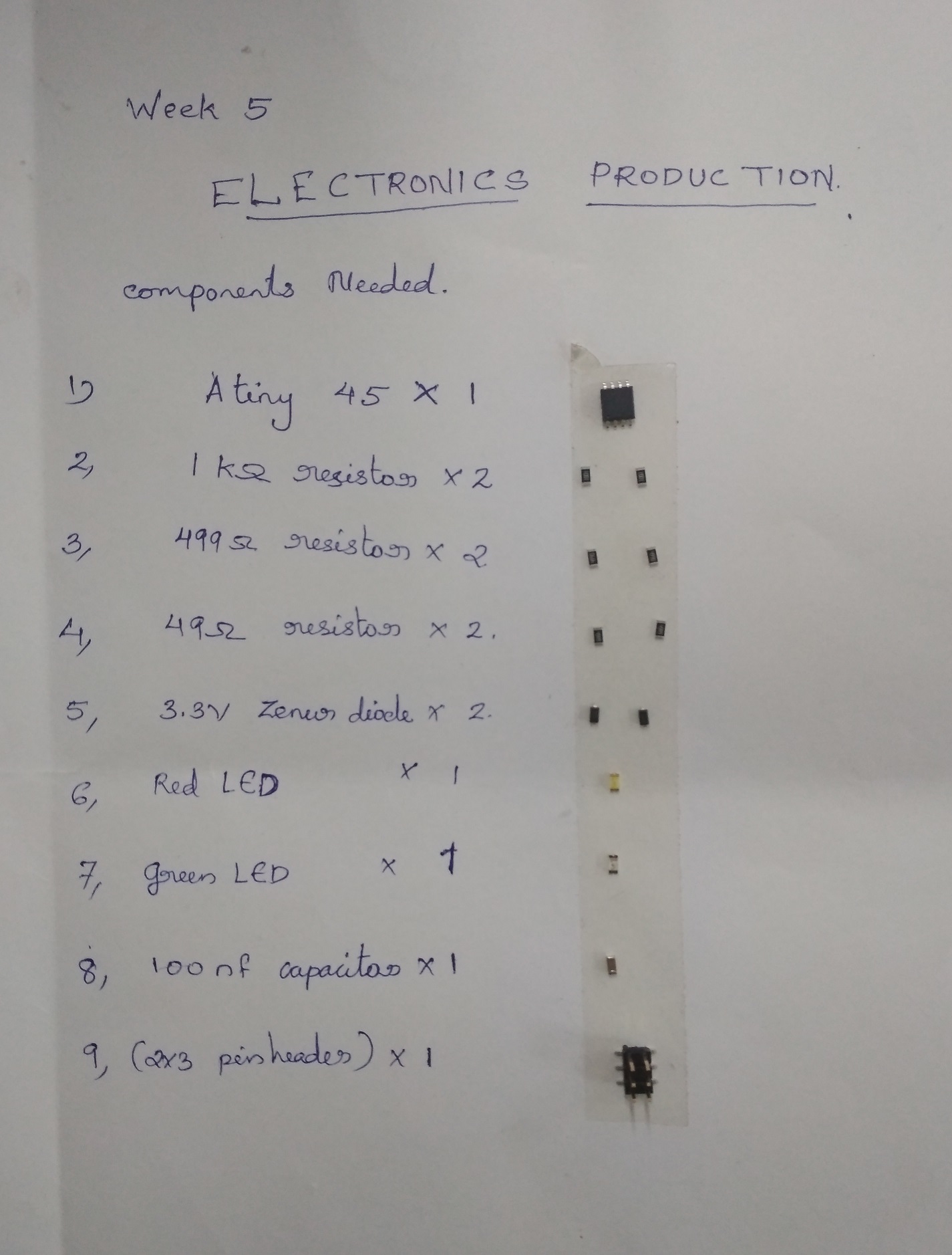
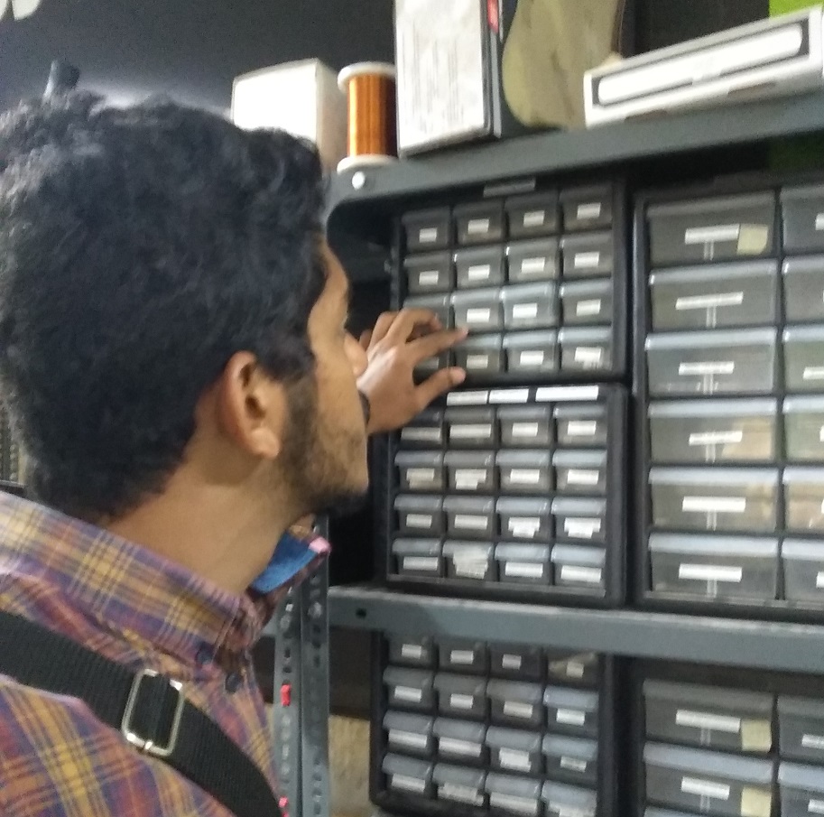
Make a list of all the reqired electronics components in a sheet of papper. Stick a long piece of double side tape onthe rigth side of the component list . We can use the double side tape to stick components that we took from the inventory .The tape will keep the components in place and it will reduce a lot of confusions in future.
Remove all unwanted residues generated during milling.
For the easynes of soldering i sticked the PCB to the table with a piece of double side tape. My instructors and fabmates helped me in soldering smd components
 Make sure the enviournment has sufficient lighting and ventilation .Using the magnifying glass could probabily reduce the strain on our eyes.I always prefer to use them
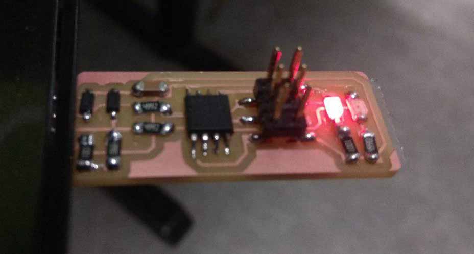
This is my finished USBtinyISP.
Programming the FabTinyISP
Once you finish soldering the components, It is time to test the connections and program the board. Look carefully at the board to see if all the connections are proper
$Loose contact
$Orientation of components
$Misalignment
$Continuity of tracks
If any components are loose or misplaced, de-solder them and put them in their correct places.If everything checks out, proceed to plug it into the USB port of your PC. If the red LED lights up everything is fine else repeat the about tests.The next step is programming the chip with the right firmware.
Software Installation
For Ubuntu and other Debian-based distributions, enter the following command, followed by your password when prompted: sudo apt-get install avrdude gcc-avr avr-libc make
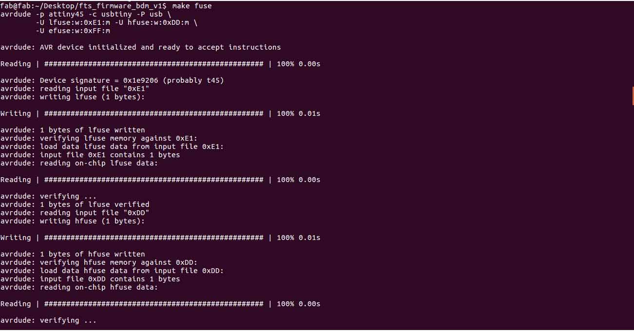
Build the Firmware
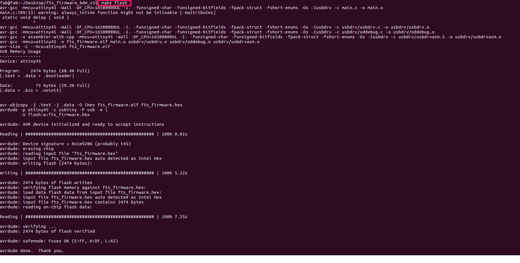
Download the firmware source code firmware source code and extract the zip file (on Linux, unzip fts_firmware_bdm_v1.zip). Open the terminal and go to the directory by using the ‘cd’ command. Once in the directory type ‘make’and click enter. This will build the .hex file that will get programmed onto the ATtiny45. When the command completes, you should now have a file called fts_firmware.hex. Continuity of tracks make
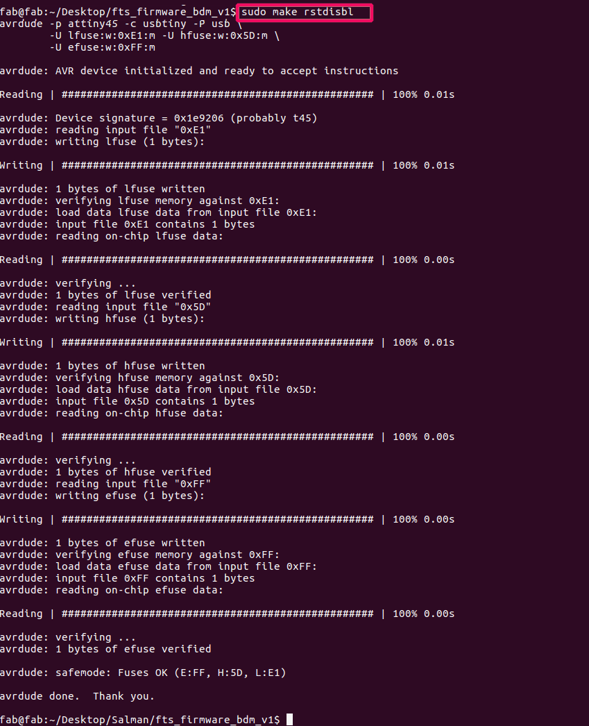
Program the ATtiny45
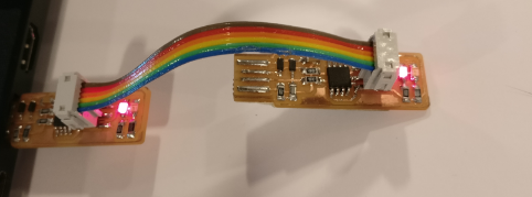
The make file of the firmware assumes that you are going to use a programmer in the usbtiny category (another fab ISP). If you’re using a different programmer, first figure out what avrdude (the programming software) calls it. Edit the file called Makefile. It is important to use a text editor intended for programmers. Near the top of the file, find the line that says: PROGRAMMER ?= usbtiny change usbtiny to whatever programmer you’re using. Plug the board into a USB port. USB2.0 is preferred over 3.0 if you have one, and use an extension cable so that you do not put strain on your board especially if your port is upside down. If you installed the red LED, it should be lit up now. If not, check the solder jumper and make sure that it is bridged. If your computer complains about a USB device drawing too much power, unplug the board and check for shorts. Connect the programmer to the ISP header on your board. Note that there are two different orientations in which you can connect the cable; it is imporatant that you get pin 1 in the right place. Pin 1 is the MISO pin and it should be connected to the MISO pin of the board you are programming.
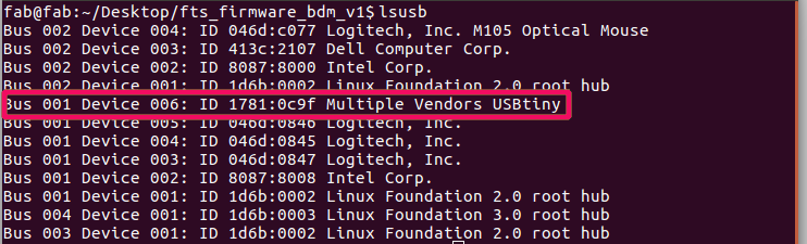
Type lsusb In terminal and ensure the device is identified
Use the three backticks to separate code.
// the setup function runs once when you press reset or power the board
void setup() {
  // initialize digital pin LED_BUILTIN as an output.
  pinMode(LED_BUILTIN, OUTPUT);
}

// the loop function runs over and over again forever
void loop() {
  digitalWrite(LED_BUILTIN, HIGH);   // turn the LED on (HIGH is the voltage level)
  delay(1000);                       // wait for a second
  digitalWrite(LED_BUILTIN, LOW);    // turn the LED off by making the voltage LOW
  delay(1000);                       // wait for a second
}
Gallery

Video
From Vimeo
Sound Waves from George Gally (Radarboy) on Vimeo.