10. Molding and casting
Group assignment:
The group assignment can be viewed using this link
Design
For the molding process I used the 3D scan of myself I made earlier to make a mold of my head.

First I needed to separate the head from the body. To do that select in the ‘’construct” section to offset a plane to skech the cut line.
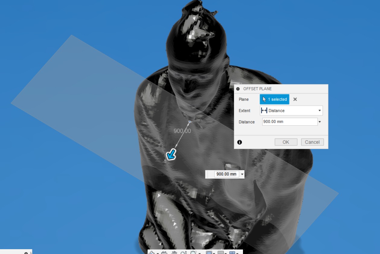
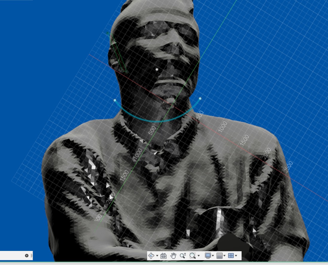
I made shore I had some distance between the plane and the body. When done sketch a line of choice to seperate the parts.
Afterwords select split body in the ‘“modify” section choose your body to plit and the the skeched line as splitting tool, click ok.
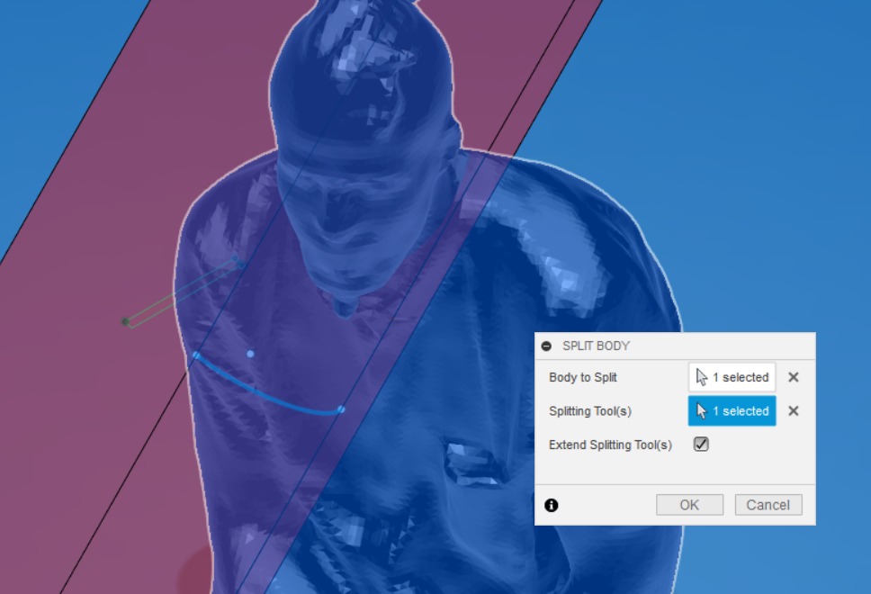
After the parts are separated you can get rid of the unnesscesary parts.

I needed a positve mold to make a negative mold to then make a possitive object. To do that I sliced the object in two and placed them in the boxex required for the molding process.
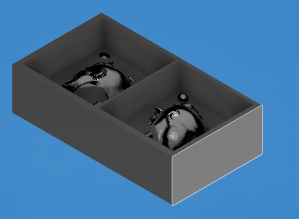
Molding
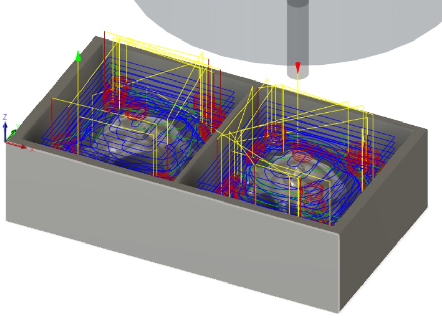
When the parts are in place you can go trough the manufacture workspace as follows.
First thing is the pocket clearing. This allows you to get rid of most unnecessary material.
Setup.
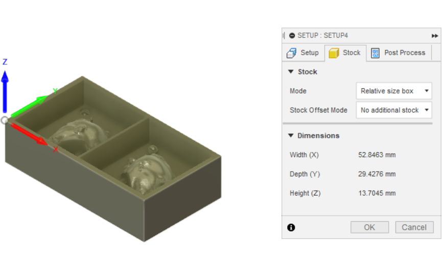
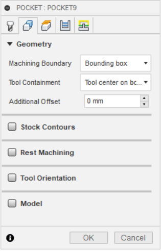
Click on setup then set up your orientation like so. Next up is ‘’Stock’‘ Here you need to select No adittional stock.
Define origin point. We chose one of the upper corners of the material. With the option Stock box point.
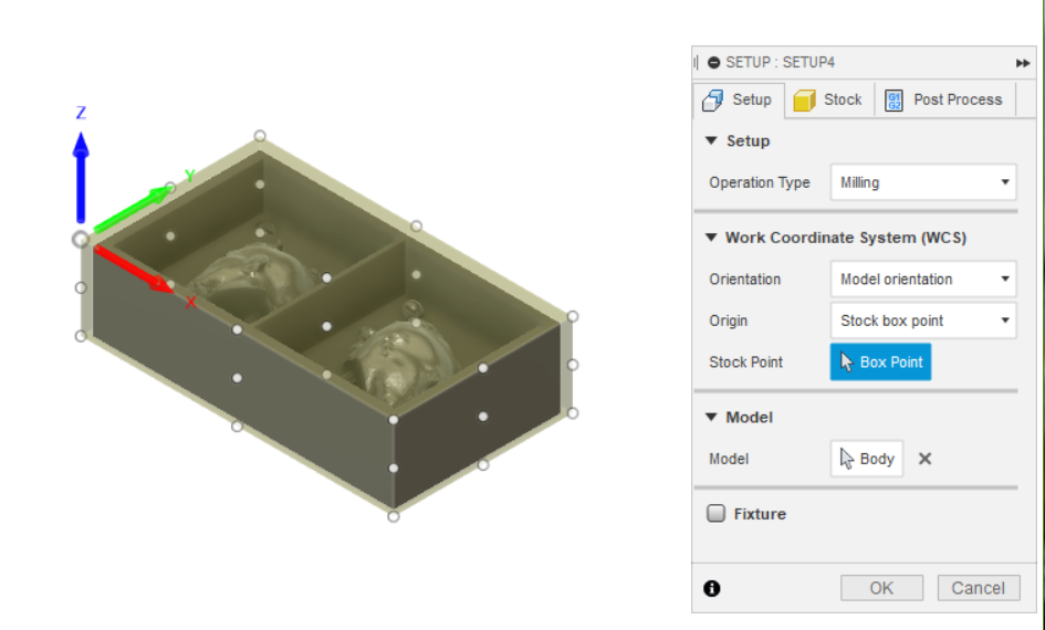
Do not forget the option: no additional stock.
Then click on

To define pocketclearing!
The tool must match the one in the lab (3,175 mm) 1/8” flat, at 10 000 rpm and feed of 100 m/min
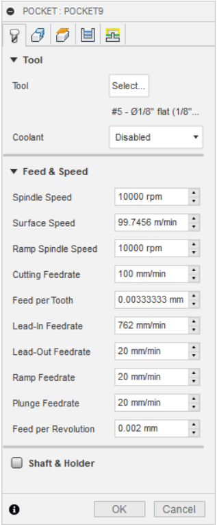
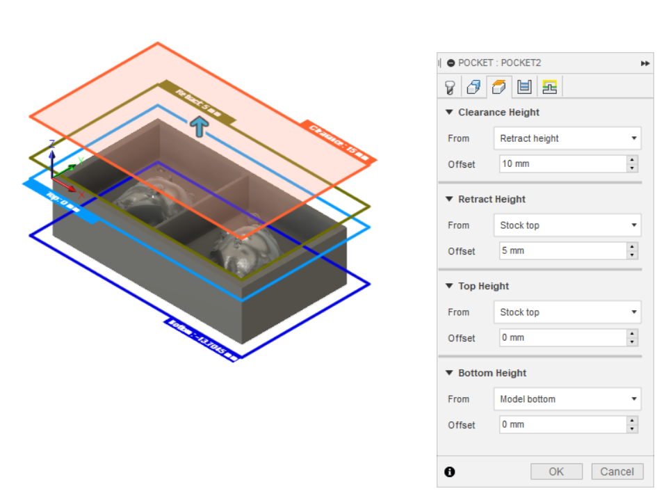
Other settings:
And clerance height we used 10 mm, for stepover we used half of the tool diameter and stepdown the tool diameter.
And befor export the job I needed the post-processing tool for WinPCnc and the stepcraft milling machine.
When satisfied, click on  to export the job.
For the finishing job the tool is 1,5 mm ball end, at 10 000 rpm and feed of 100 m/min. For clerance height we used 10 mm, for stepover we used half of the tool diameter and stepdown the tool diameter. Later, I found that I could hve used a bigger stepovr for a better finish.
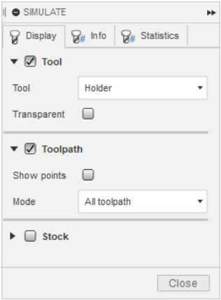
Now you can simmulate your milling by clicking the simmulate button.

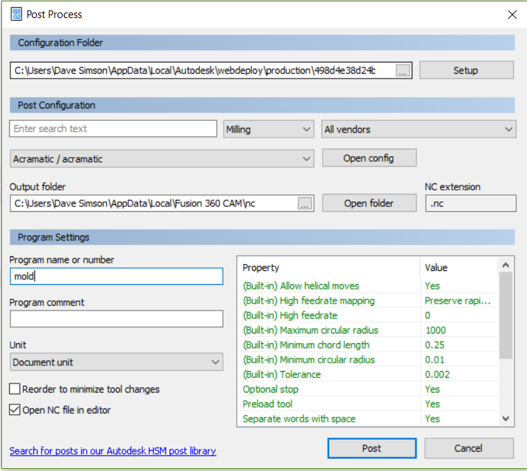
If satisfied click on G1G2 immage and dont forget closing the file name with .nc. Of to the milling .
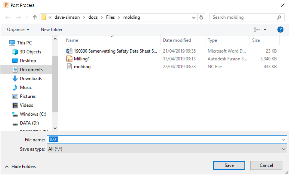
Here, you can determine the output folder:
You can safe it on a USB stick or you can directly connect to the Machine of choice, in my case the Stepcraft600.
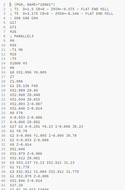
After saving, you will get a code example. There you can see if your starting point is according to plan.
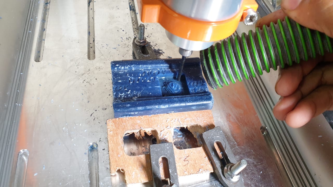
Machining
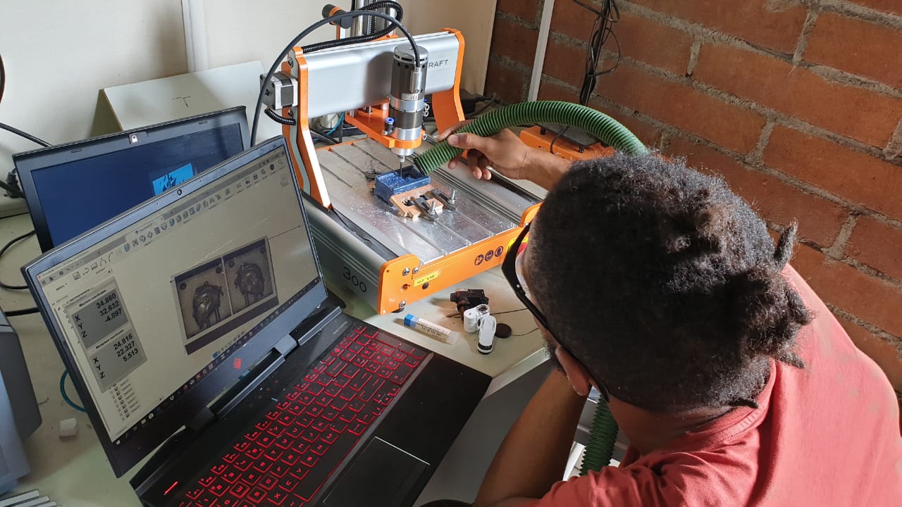
I attached the material to the stepcraft, loaded the gcode file for rough cut, set the zero on top of the material (as defined in fusion36).
In the first try, I had offsets problems which caused the machine to plunge to deep into the material.

Later on I Learned from Pascal, a classmate, that by aligning the offset in fusion 360 you can fix the plunge problem.
Second problem was, I forgot to command the machine to its origin point. This caused me to loose my precision.
I tried fixing it by recovering the origin point through eyeballing it. However, I do not recommend this.
The slightest mistake causes a large enough offset that will ruin your work.
I consulted a classmate Julie Sundar, who pointed me into the right direction to fix the problem.
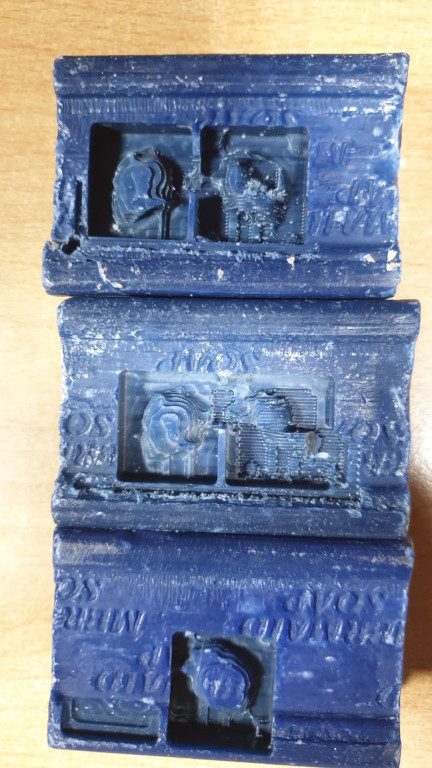
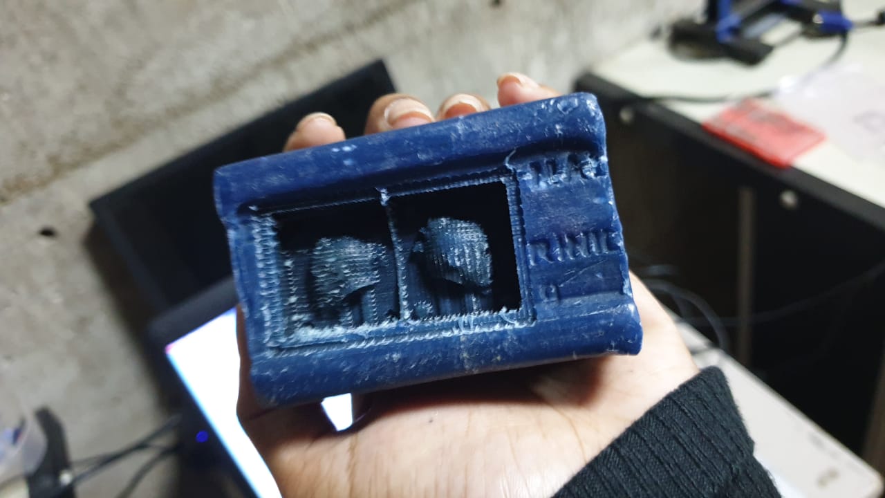
Finally, I had a good result.
Casting:
Prepare:
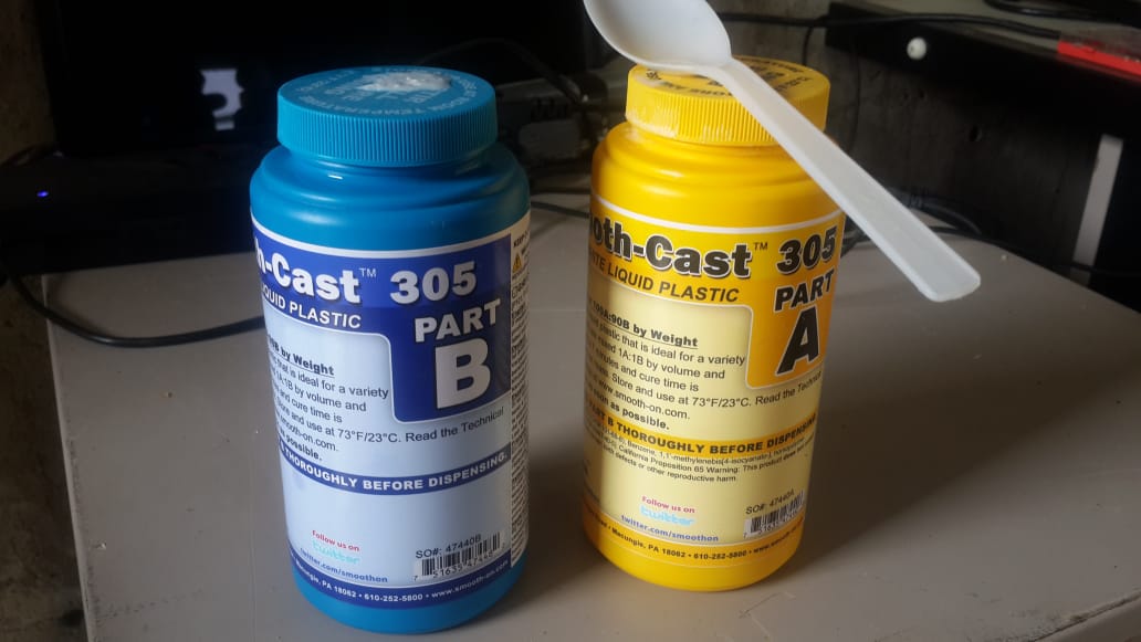
OOMOO 25 rubber Silicone and Smooth Cast Liquid plastic in a convenient one-to-one by volume mix ratio.
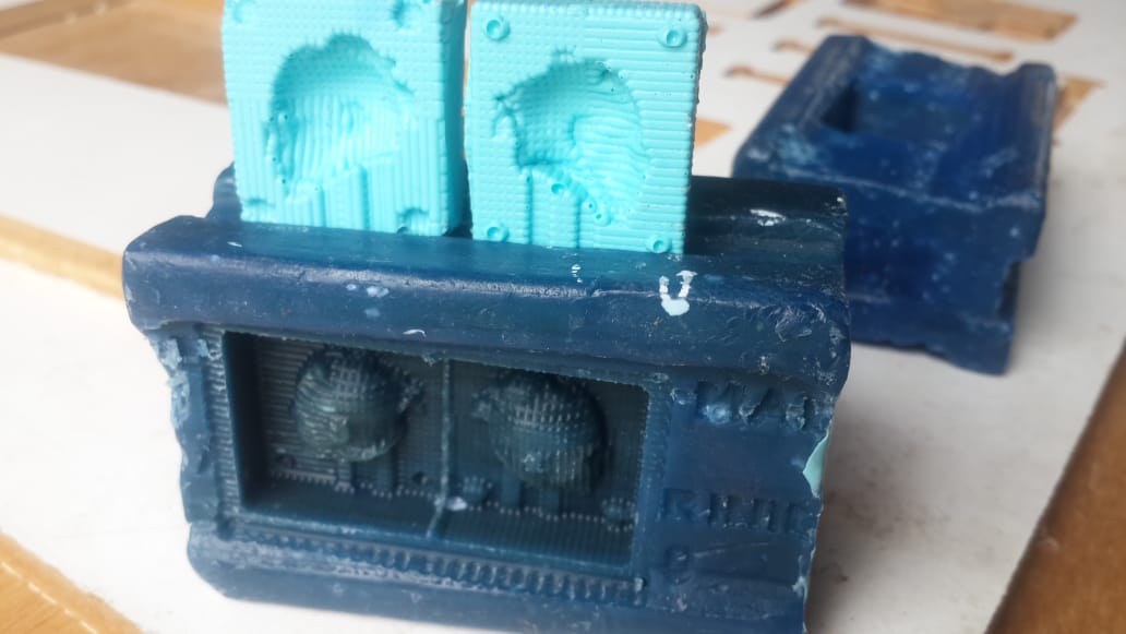
And pour the blue mix into the two parts of the mold. Then let dry for a few hours.
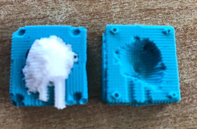
Then, the smooth-cast 305 is also mixed in equal parts and pour in the soft mold.
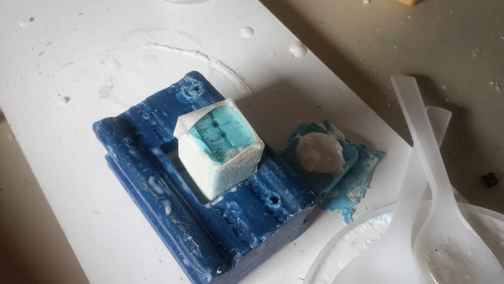
And after one day of drying this is my result