Assignment 14: Mechanical Design
Project Description
Design and fabricate a machine
Assignment Details
- Group Assignment:
- Design a machine that includes mechanism+actuation+automation
- Build the mechanical parts and operate it manually
- Individual assignment:
- Document the group project and your individual contribution
Overview
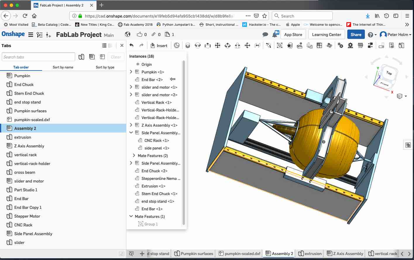
Since I am working alone and my final project is a machine, this week's assignment is a start on my final project, a Pumpkin CNC Lathe. I described the assemblies and parts in Assignment 12: Applications and Implications. This week's discussion covers machine design decisions and fabrication.
The short video shows a quick summary of machine design, fabrication and actuation.
Key Design Decisions
Vertical Gantry Movement
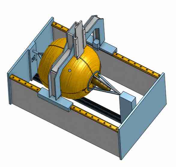
The key to any machine is the design of movement. In the case of a CNC, the decisions relate to how to move the cutting head. Since this is a lathe, a gantry is needed to move the cutting tool and a rotation axis moves the pumpkin. The gantry is divided into decisions about how to move along an axis and how to actuate the movement. The first decision was to orient the pumpkin vertically on a rotating platform and as a result the gantry moves up / down with a second axis in / out.
This design leverages the rack and pinion in a pinch block created by Jens Dyvik's "Chamfer Rail". The key to this design is the teeth in the rack coupled to the teeth in the pinion, gliding in a "pinch" block. The figure above shows the pinch block. The rails consist of a 45 chamfer and a flat guide.
Motor Location- Fixed Chamfer Rail / Pinion, Moving Rack
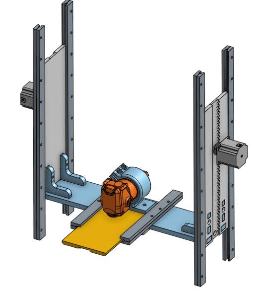
This design reverses the traditional use of the rack and the chamfer rail. Normally the rack is fixed and the gantry attached to the chamfer rail which slides on the rack. The pinion is attached to the motor and rail assembly which slides when the pinion rotates against the fixed rack. If the rack was fixed, this would mean that the motors (and pinions) would need to move. In this case that would mean that the motors would need to lift the weight of the gantry and the motors. Fixing the motors (and pinion) to the case and moving the rack reduced the weight (and associated torque) needed to move the gantry motors by about 4.5 pounds. The figure above shows the fixed motor with pinion that moves the rack attached to the vertical gantry. Since the end of the rack cannot move past the pinion, the motors and attached pinions are located at the top of the case with the router located at the bottom of the vertical gantry. This gives the maximum rail / cutter router travel.
No Lathe Chuck or End Stock
The decision to orient the pumpkin vertically, simplified the design by removing the need for lathe chuck and end stock. The pumpkin's weight sits on a rotating platform. This platform spins based on a "Lazy Susan" circular bearing. The pumpkin sits on sharp pegs attached to the rotating platform. A stepper motor attached to the case rotates a pulley attached to a belt (not shown attached in the figure) which rotates a pulley on the base of the rotating platform. The platform has several sharp pegs which are pushed into the pumpkin. The sharp pegs rotate the pumpkin.
Fabrication: Prefer Make over Buy
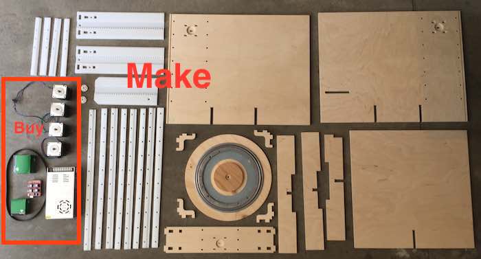
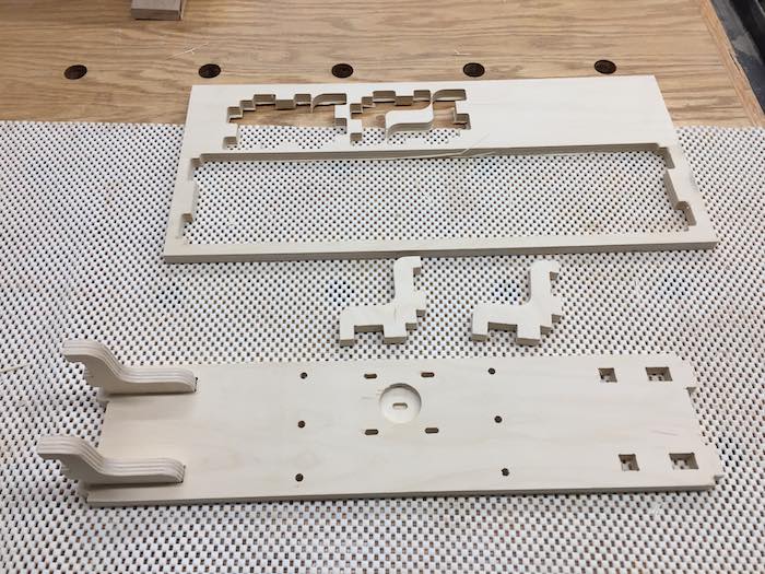
The figure below shows most of the parts used in the Pumpkin Lathe machine. Key to this design was a decision to make rather than buy - most of the parts are fabricated. Only the stepper drivers, motors, power supply, nuts / bolts, lazy susan bearing, and timing belt are purchased, everything else was fabricated.
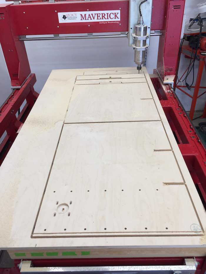
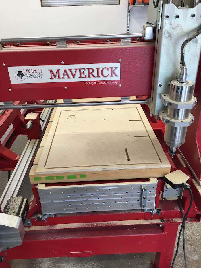
The next 2 figures show the large CNC cutting the 3 sides of the case out of .5" Baltic birch plywood. Note the slots for the cross braces, holes for rails, and holes for stepper motors.
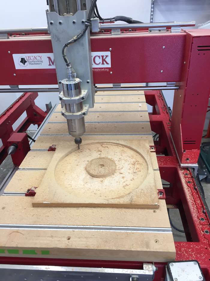
Next the rotating platform was cut from .5" Baltic birch plywood. There is a section of the platform that extends through the hole in the lazy susan which holds the timing belt pulley. The hole in this extension holds the boss from the timing belt pulley. The timing belt sits just below the lazy susan.
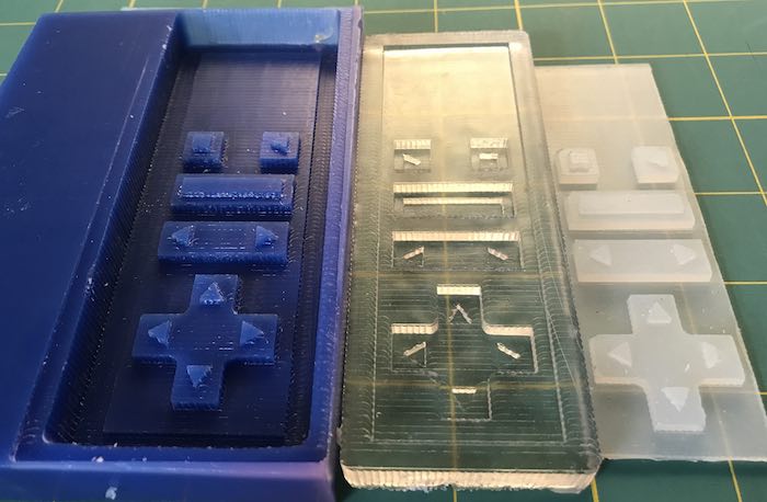
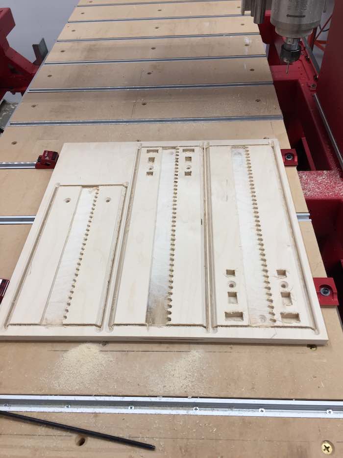
To validate the g-code for the rack cut, a wooden prototype was created.
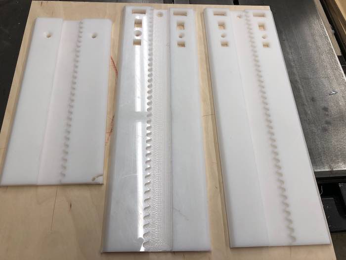
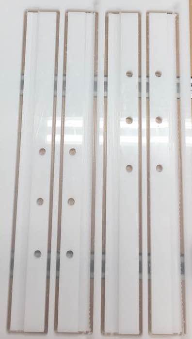
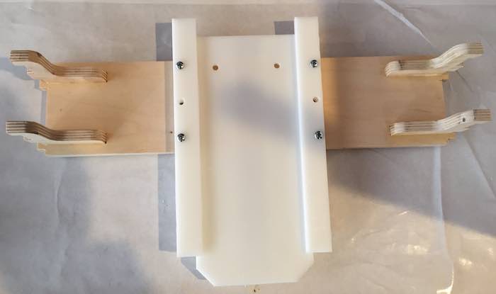
After validating the prototype, the final racks were fabricated from 3/8" HDPE. Note the slots for integration with the gantry cross brace.
Next the rails which form the pinch block were fabricated from 3/8" HDPE. This figure shows the in / out rails attached to the gantry cross brace.
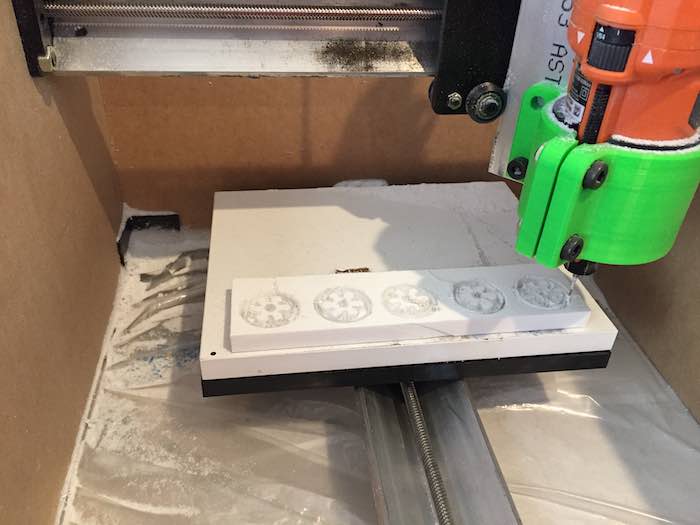
Next the pinions were fabricated from 1/2" HDPE on the small CNC. The pinions have a flat spot that matches the stepper shaft.
Assembly
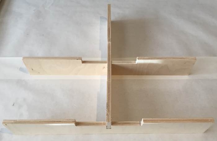
First the cross braces where assembled.
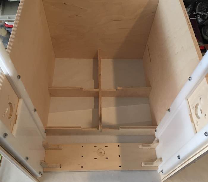
Next, the cross braces were inserted into the right and left case sides.
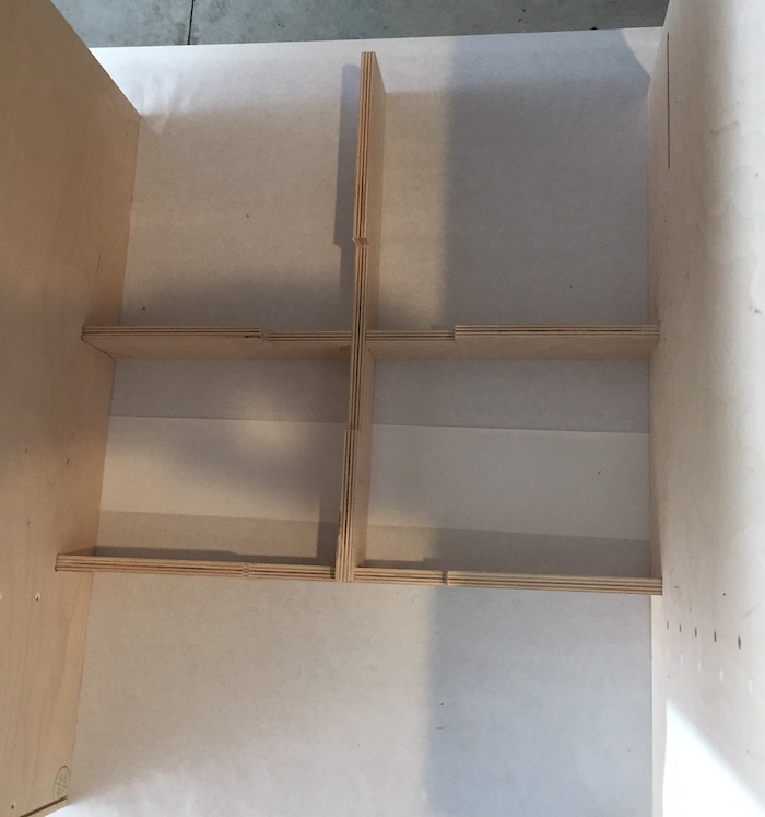
Next, the gantry cross brace was assembled.
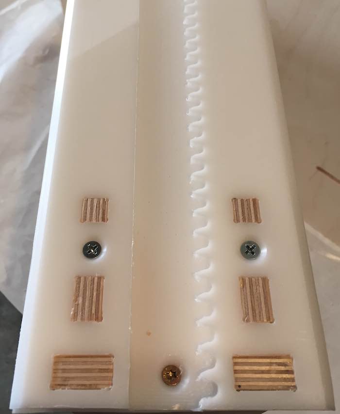
The figure below shows the assembled cross brace with the in / out rack and rails.
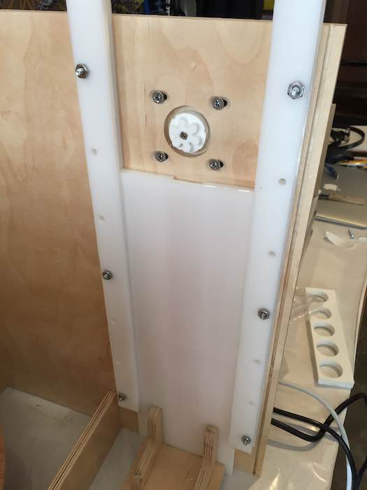
The figure below shows the vertical gantry rack integrated into the cross brace. Tabs from the cross brace press fit into the vertical rack and are held with screws into the plywood. This forms a very stiff cross brace.
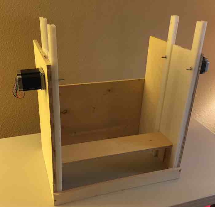
Next the vertical gantry was integrated into the vertical rails attached to the sides of the case. The fit of the rack in the rails was adjusted for smooth movement. The HDPE on HDPE joint has surprising little friction.
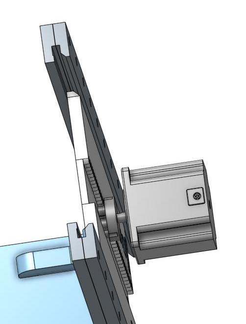
The figure below shows the pinion in the pocket cut attached to a hidden stepper motor. The teeth on the pinion mesh with the teeth on the hidden side of the rack below the pinion.
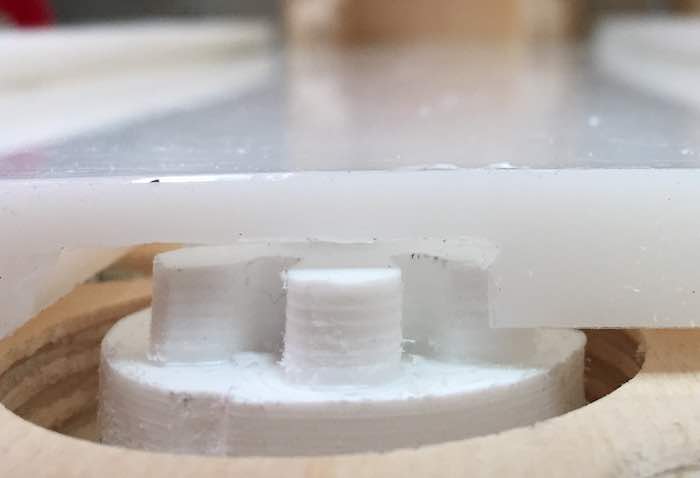
A close up of the rack - pinion interface is shown below.
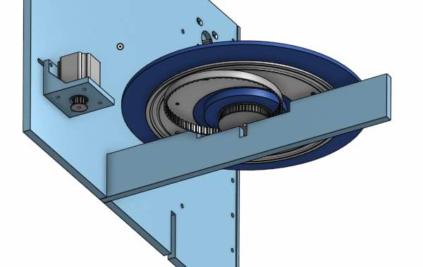
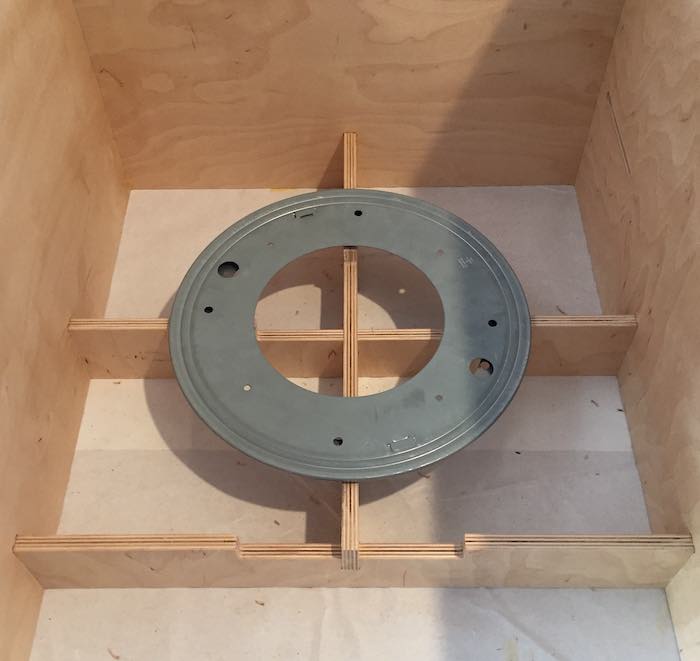
Next the lazy susan bearing was attached to the cross brace.
The rotating platform was attached to the lazy susan with the timing belt pulley on the bottom.
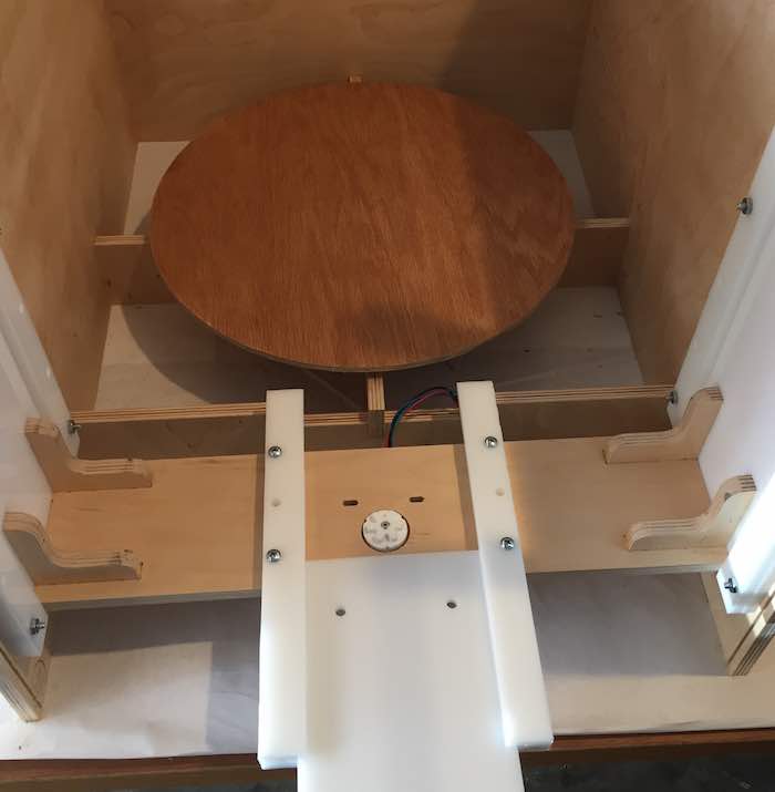
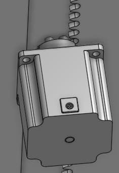
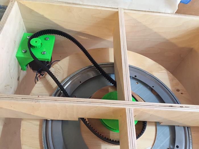
The figure below shows a bottom up view of the timing belt pulley attached to the rotating platform. The belt is on order from McMaster Carr. The belt shown is a placeholder which is not the correct size. A 3D printed bracket holds the stepper that drives the rotating platform.
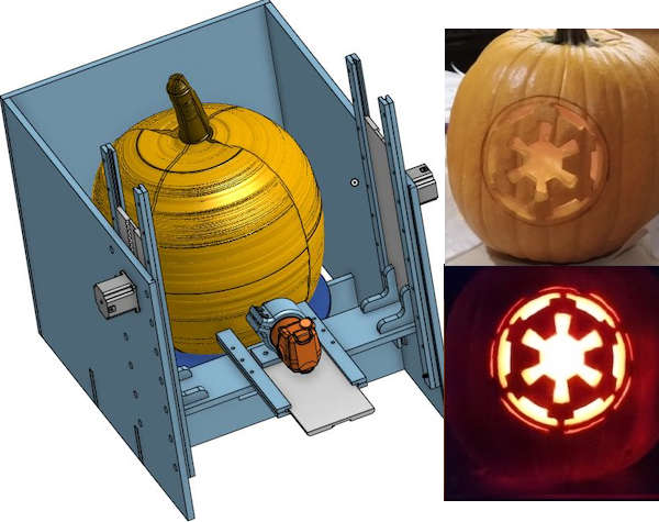
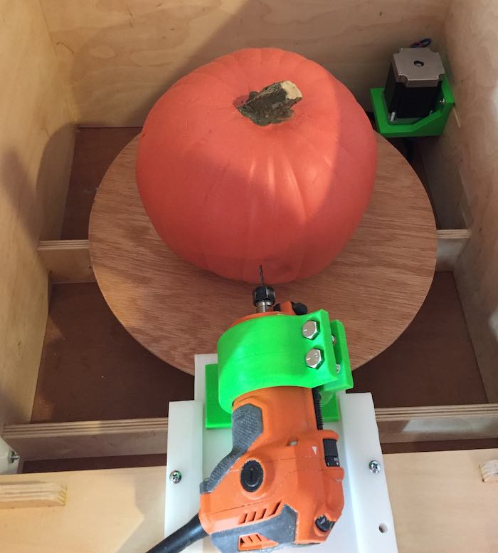
The last figure shows the router in a 3D printed bracket with a simulated pumpkin. Note: this pumpkin is much smaller than the anticipated "real" pumpkin.
Reference Files
Related Projects