Literature Survey
Sensors
I will be using 3 tyes of sensors:
1.2* Thermocouple K
2.Light Dependent Resistor(LDR)
3.Soil Moisture Sensor
Route 1
Route 2
The device will be used for generating data of capsicum farming at Vigyan Ashram. The standard data isn’t available.
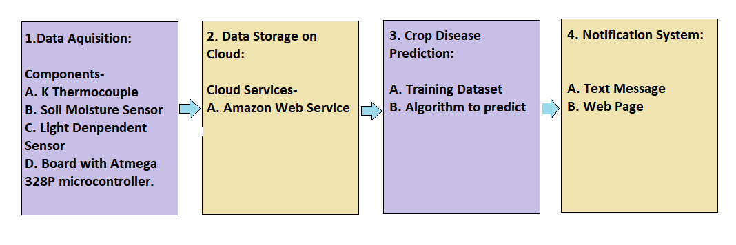
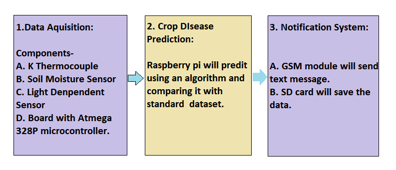
So, now the objective of the project is to make a device which can:
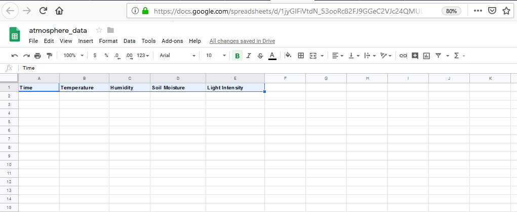
1. Measure the temperature, soil moisture, humidity and light intensity and store the data on cloud and SD card.
2.The person on ground should be able to select the pest density and visual symptoms and inform if pesticide/insecticide has been sprayed.
Cloud Service to Record daily Data. Digital thermometer to measure temperature and humidity. Soil moisture sensor to measure soil humidity. Photodiode to measure light intensity. This data should be stored in SD card and sent to cloud using Amazon Cloud Service.
Step 1:DS18B20 connection on Arduino:


- The DS18B20 digital thermometer provides 9-bit to 12-bit Celsius temperature measurements.
- The DS18B20 communicates over a 1-Wire bus that by definition requires only one data line (and ground) for communication with a central microprocessor. In addition, the DS18B20 can derive power directly from the data line (“parasite power”), eliminating the need for an external power supply.
- Power supply circuit: what exactly is parasite power supply? WHat is the role of the resistor??

- All communication with the DS18B20 begins with an initialization sequence that consists of a.A reset pulse from the master followed by b.A presence pulse from the DS18B20. When the DS18B20 sends the presence pulse in response to the reset, it is indicating to the master that it is on the bus and ready to operate. During the initialization sequence the bus master transmits (TX) the reset pulse by pulling the 1-Wire bus low for a minimum of 480µs. The bus master then releases the bus and goes into receive mode (RX). When the bus is released, the 5kΩ pullup resistor pulls the 1-Wire bus high. When the DS18B20 detects this rising edge, it waits 15µs to 60µs and then transmits a presence pulse by pulling the 1-Wire bus low for 60µs to 240µs.
I have used the following libraries: 1. Github-Temperature Control Library 2. Github-PaulStoffregen-Onewire
Refrences: 1.Datasheet of DS18B20 2.
Refrences: Arduino programme
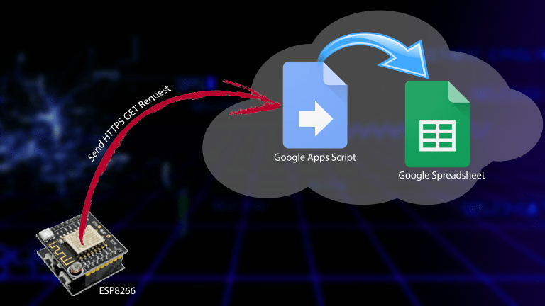
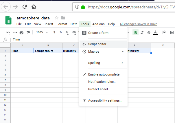
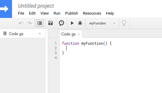
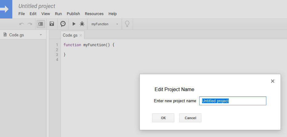
Step 2: Sending data from wifi to google sheet: wifi to drive
conclusion: I want to send data from board to google drive and ThingSpeak both.
I have to understand the
Step 3: To understand the connections of wifi..
ESP8266 Wifi module interfacing module with Arduino
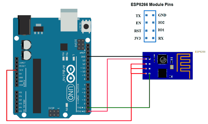
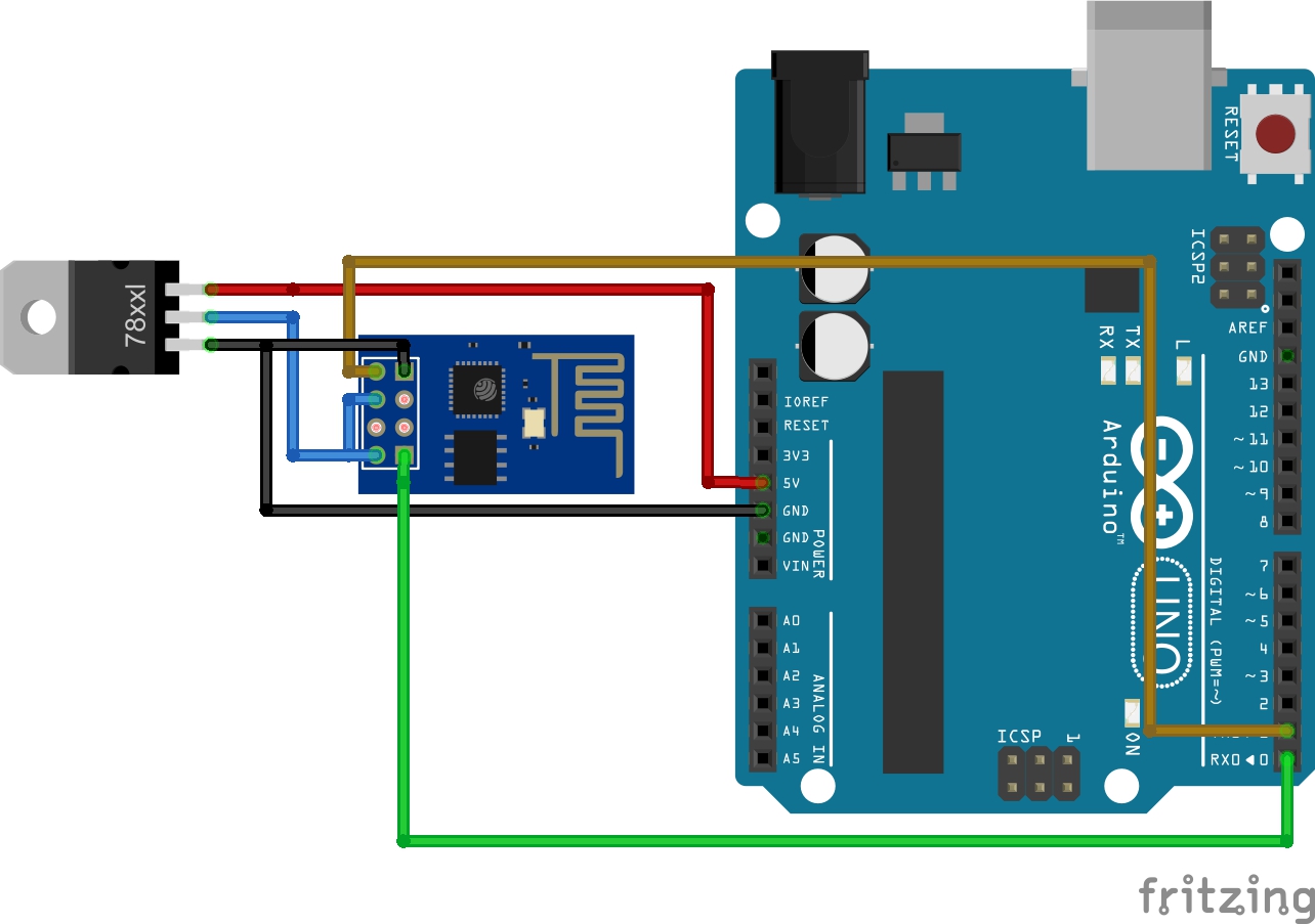
Wifi needs 3.3V and my supply from outside will be 5V. What are the ways to decrease the voltage:- 1. Adding a resistor 2. Voltage regulator
I need a SMD voltage regulator.
Solution: I will be using LM1117 voltage regulator.
 Step 4:
Step 5:
Atmega 328 has 2 VCCs and 3 GNDs, now which VCCs and GNDs are to be connected??
I have to study the datasheet of ATmega 3288P-mainly pinout diagram.
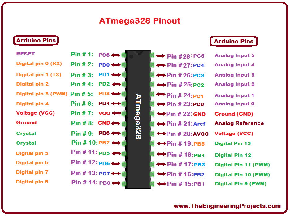 It has become easy for me because I have to just compare the pins of arduino to Atmega328P.
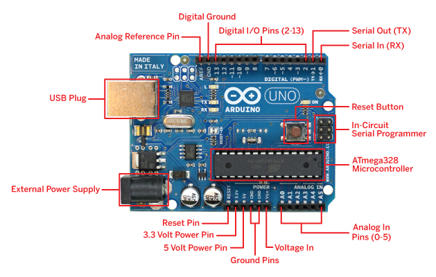
Step 6: It was important to understand Arduino
step 7: why is copper conducting material??
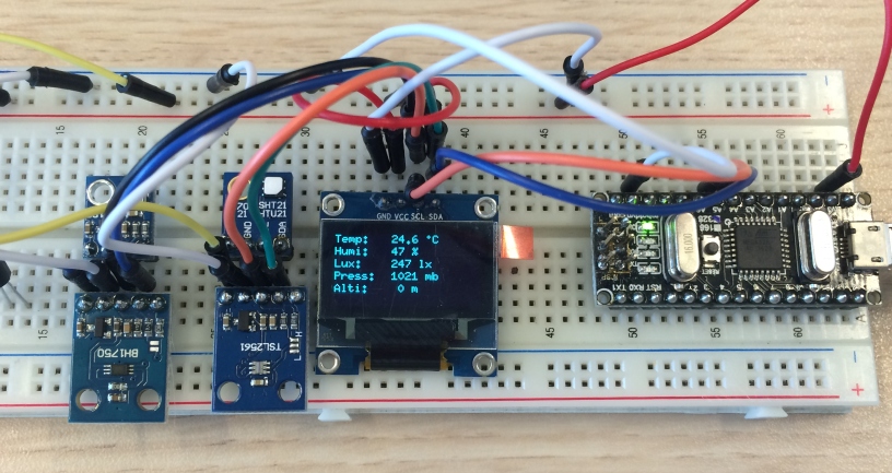
step 8:0.96” OLED display 4PIN E-273
OLED I2C Display Arduino Tutorial
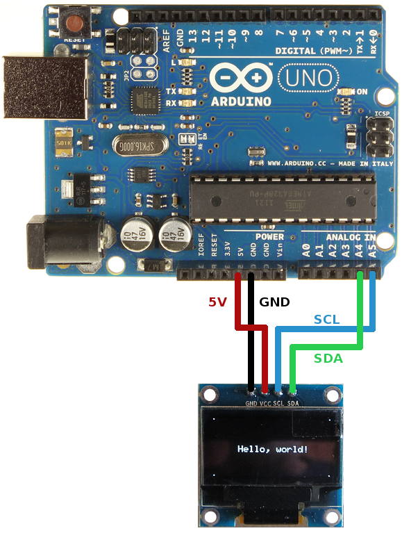
I have to confirm that ths LED works on 5V??
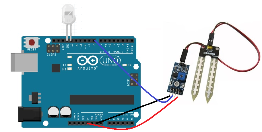
Step 9: Soil moisture sensor: What will be the difference to have digital or analog output??
The soil moisture sensor will work on Analog mode. The differnce is in analog mode it will give values in decimal.
I have to confirm that this will need 5V?(Yes, We need 5V)
It should work on Analog or digital mode??(Analog mode)
Soil moisture sensor on Arduino
FC-28 soil moisture sensor? I want to do it on arduino and check
Step 10: Light intensity digital sensor BH1750:1st BIG CHALLENGE This has 5 pins which includes SDA and SCL, I have already used these 2 pins in OLED. WHat should be done in this case??OLED with sensors: This website says it is possible to sensors and OLED on a single I2C bus.
When do we call I2C bus principle??
Pins of BH1750 digital light sensor-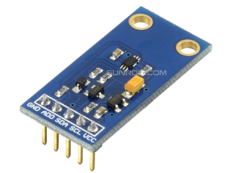 BH1750 light sensor with Arduino
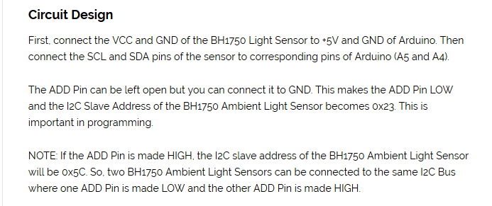
There is one pin on BH1750 ADD which isn’t connected. Why so??
BH1750 light sensor with Arduino
There is one pin on BH1750 ADD which isn’t connected. Why so??
Pin Description
VCC – 3.3V to 5V
GND – GND
SCL – I2C Clock
SDA – I2C Data
ADD – I2C Device Address
I am not able to understand this paragraph:
Step 11: I have to try SD card and RTC on arduino 2nd Try: I have to try Wifi module and OLED module
Step 12: Power Jack: 2 wires are connected to GND and 1 to VCC. I have to confirm whether I have chosen the right power jack.
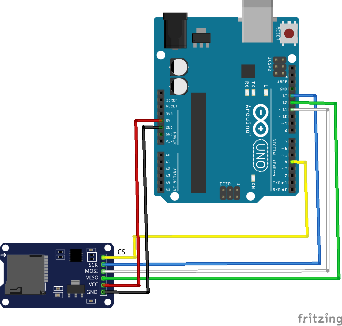
Step 13:SD card-Pin out diagram & connection with Arduino-
Step 14:What is RTC? and it’s fuction?? How will it be be connected to SD card?
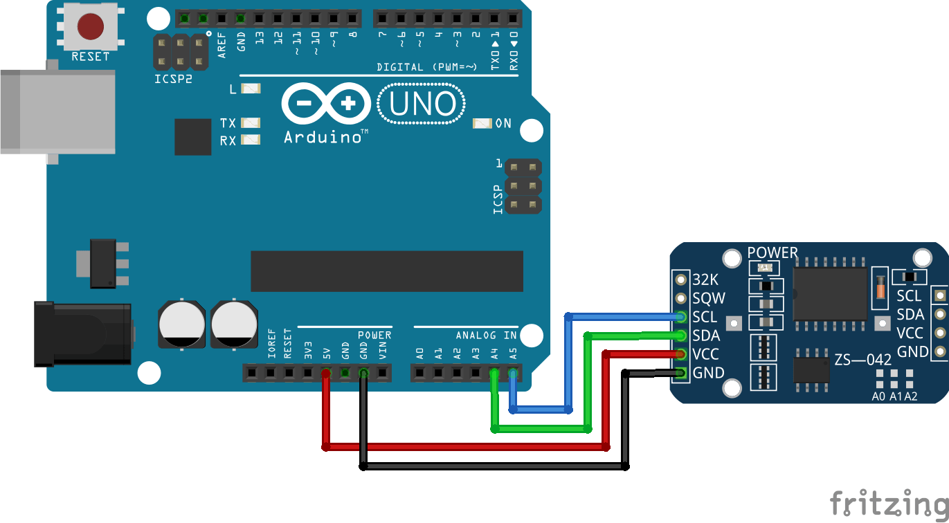 The first question that comes here is why we actually need a separate RTC for our Arduino Project when the Arduino itself has built-in timekeeper. Well the point is that the RTC module runs on a battery and can keep track of the time even if we reprogram the microcontroller or disconnect the main power.
Step 15: Bluetooth model-
I have downloaded the source code,
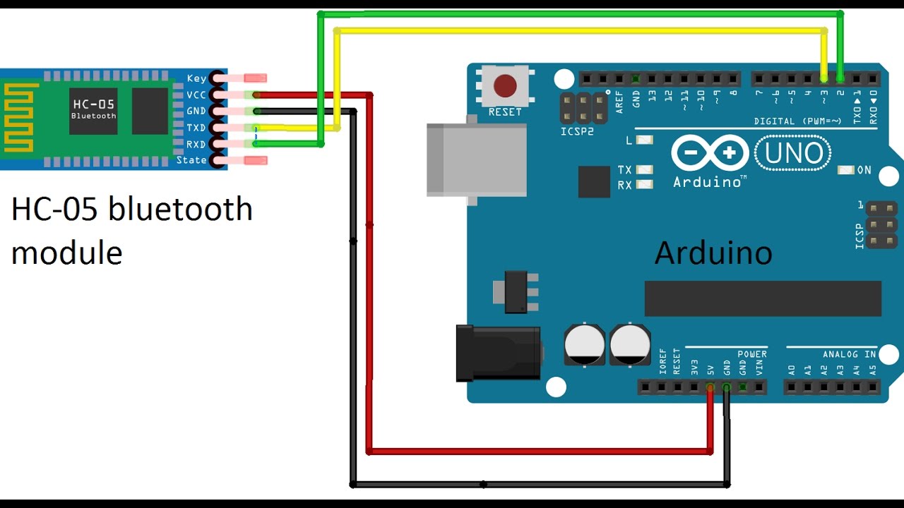 Arduino with Bluetooth sensor
Step 16: I have to decide the other components to be used: 1. LED-to show power + resistor 2. LED-to show programming + resistor 3. FTDI-when is it used?? Do I need it? It is used when we connect connect board to computer and 4. 6 pin connector for programming- 8. resistor-Reset + GND 9. Capacitor- VCC and GND 10. Zenier diode- DO I have to use it? I donot need zenier diode in my board coz I don’t need anywhere to send current only in 1 direction. 11. Switch- 12. Resonator-
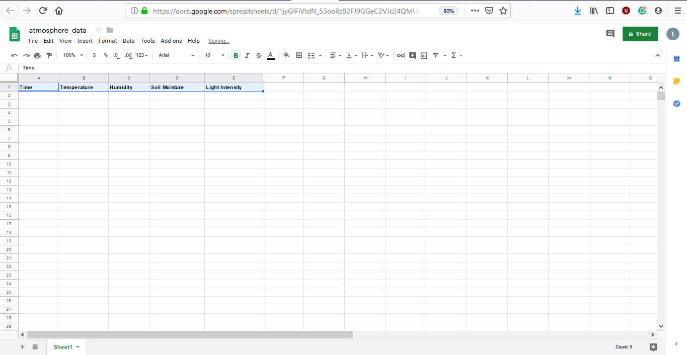
Step 17: Sending Data on CLoud:-
Code Example
Use the three backticks to separate code.
/*
//https://docs.google.com/spreadsheets/d/1sUFwKGAMzYWl6Y9RUM-dyWgsE1BfPqMzToBBm7JHK5g/edit#gid=0
//-----------------------------------------------
// Author: Trieu Le
// Email: lethanhtrieuk36@gmail.com
// Publish date: 07-Oct-2015
// Description: This code for demonstration send data from ESP8266 into Google Spreadsheet
// GET request syntax:
// https://script.google.com/macros/s/<gscript id>/exec?header_here=data_here
// Modifyed by Moz for Youtube changel logMaker360 for this video: https://youtu.be/fS0GeaOkNRw 24-02-2018


//-----------------------------------------------
/**
* Function doGet: Parse received data from GET request,
  get and store data which is corresponding with header row in Google Spreadsheet
*/
function doGet(e) {
  Logger.log( JSON.stringify(e) );  // view parameters
  var result = 'Ok'; // assume success
  if (e.parameter == 'undefined') {
    result = 'No Parameters';
  }
  else {
    var sheet_id = '1sUFwKGAMzYWl6Y9RUM-dyWgsE1BfPqMzToBBm7JHK5g';      // Spreadsheet ID
    var sheet = SpreadsheetApp.openById(sheet_id).getActiveSheet();     // get Active sheet
    var newRow = sheet.getLastRow() + 1;
    var rowData = [];
    rowData[0] = new Date();                                            // Timestamp in column A
    for (var param in e.parameter) {
      Logger.log('In for loop, param=' + param);
      var value = stripQuotes(e.parameter[param]);
      Logger.log(param + ':' + e.parameter[param]);
      switch (param) {
        case 'temperature': //Parameter
          rowData[1] = value; //Value in column B
          result = 'Written on column B';
          break;
        case 'humidity': //Parameter
          rowData[2] = value; //Value in column C
          result += ' ,Written on column C';
          break;
        default:
          result = "unsupported parameter";
      }
    }
    Logger.log(JSON.stringify(rowData));
    // Write new row below
    var newRange = sheet.getRange(newRow, 1, 1, rowData.length);
    newRange.setValues([rowData]);
  }
  // Return result of operation
  return ContentService.createTextOutput(result);
}
/**
* Remove leading and trailing single or double quotes
*/
function stripQuotes( value ) {
  return value.replace(/^["']|['"]$/g, "");
}
//-----------------------------------------------
// End of file
//-----------------------------------------------
Deploy as Webpage:
I2C Bu programming: I2C between 2 arduinos 1.How do we define Master? 2. How do we define Slave? How do we defin address?? 3. How will Master come to know which Slave to order??
Important Learnings: 1. I2C requires two digital lines: Serial Data line (SDA) to transfer data and Serial Clock Line (SCL) to keep the clock. 2. Each I2C connection can have one master and multiple slaves. 3. A master can write to slaves and request the slaves to give data, but no slave can directly write to the master or to another slave. Every slave has a unique address on the bus, and the master needs to know the addresses of each slave it wants to access. 4. Each I2C bus can support up to 112 devices. All devices need to share GND. The speed is around 100 kb/s—not very fast but still respectable and quite usable. It is possible to have more than one master on a bus, but it’s really complicated and generally avoided. 5. I2C is not designed for long cable lengths. Depending on the cable type used, 2 meters might already cause problems. 6. We need wire.h library
Conclusions and Learnings: 1. I didn’t like routing at all. It consumed a lot of time. 2. The components which ahve connection directly only to I>C must be kept near it.
Programming on Arduino: 1. We have to add programme to Master and slave independently. how am I going to burn the programme the slave differently?? I don’t have to programme the Bluetooth,RTC and Photodiode. I have to understand the address.
I have to include the function of serial read(baud is 9600 which is rate at which the board will communicate) and display in arduino.
Programming OLED on Arduino:
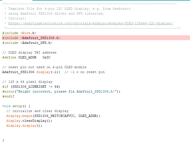 Two Arduino libraries must be installed to start using the display. The SSD1306 driver library is used to initialize the display and provide low level display functions. The GFX library provides graphics functions for displaying text, drawing lines and circles, etc. Both these libraries are available from Adafruit.
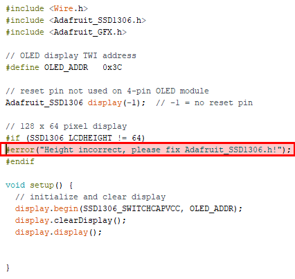
Error:- he SSD1306 driver isn’t set up for the Geekcreit OLED display by default. The display size must be changed in the driver before it can be used. If it is not changed, an error message will appear when attempting to verify the example sketch (see the section below) in the Arduino IDE:
error (“Height incorrect, please fix Adafruit_SSD1306.h!”);
I have to understand the use of every library:
Code for “Hello Tushar on OLED”
#include <Wire.h>
#include <Adafruit_SSD1306.h>
#include <Adafruit_GFX.h>

// OLED display TWI address
#define OLED_ADDR   0x3C

Adafruit_SSD1306 display(-1);

#if (SSD1306_LCDHEIGHT != 64)
#error("Height incorrect, please fix Adafruit_SSD1306.h!");
#endif

void setup() {
  // initialize and clear display
  display.begin(SSD1306_SWITCHCAPVCC, OLED_ADDR);
  display.clearDisplay();
  display.display();

  // display a pixel in each corner of the screen
  display.drawPixel(0, 0, WHITE);
  display.drawPixel(127, 0, WHITE);
  display.drawPixel(0, 63, WHITE);
  display.drawPixel(127, 63, WHITE);

  // display a line of text
  display.setTextSize(1);
  display.setTextColor(WHITE);
  display.setCursor(27,30);
  display.print("Hello, world!");

  // update display with all of the above graphics
  display.display();
}

void loop() {
  // put your main code here, to run repeatedly:

}
Screen Coordinates and Dimensions
- After initializing the display, the above sketch then draws a pixel at each extreme of the display by using drawPixel() to place a pixel in each corner of the screen. The first parameter passed to drawPixel() is the screen X coordinate and the second parameter is the screen Y coordinate.
- Screen dimensions are 128 by 64 pixels and pixel coordinates start at 0, 0 for the top left pixel. This means that the X coordinates for the screen are from 0 to 127 (not 1 to 128) left to right; and Y coordinates are from 0 to 63 (not 1 to 64) top to bottom. As can be seen in the sketch and on the display, the corner pixels are at the following coordinates: Top left pixel – x = 0, y = 0. Top right pixel – x = 127, y = 0. Bottom left pixel – x = 0, y = 63. Bottom right pixel – x = 127, y = 63.
How to Write a Line of Text to the Display
-
Use print() to write a line of text to the display as shown in the above sketch. Before writing text to the display, call setTextSize() and setTextColor(). Because this is a monochrome display, setTextColor() must be passed WHITE for the text to be seen on a black background.
-
Text that is written to the display is positioned by calling setCursor() to move the invisible cursor to the desired position. X and Y coordinates are passed to setCursor() to move the cursor and start of text to these pixel coordinates.
-
Basic Principle of Operation of the Graphics Library:
All text and graphics are written to buffer memory in the Arduino. Only when display() (display.display() in the above code) is called is the contents of the buffer displayed on the screen. This means that any text and graphical objects such as lines and circles will not appear on the screen until display() is called.
- Where is the Adafruit Logo Stored that Appears on the Screen?
If the display() function is called without first calling clearDisplay() as shown in the following code, the Adafruit logo appears on the screen. Where does this logo come from?
void setup() { display.begin(SSD1306_SWITCHCAPVCC, OLED_ADDR); display.display(); }
Memory used for the screen buffer is initialized with the Adafruit logo in the Adafruit_SSD1306 driver library. This code is found in the Adafruit_SSD1306.cpp file in the Arduino libraries folder at libraries → Adafruit_SSD1306. The logo consists of hexadecimal code used to initialize the buffer[] array near the top of the Adafruit_SSD1306.cpp file.
Calling clearDisplay() clears the logo from memory allowing new text and graphics to be written to the buffer.