Exercise 12. 📱 Interface and Application Programming 💻 📝 📲 🐍
At the end of this exercise, I should be able to:
1. Compare and contrast tools for interface and application programming.
2. Write an application that interface a user with an input (exercise 9) and/or output (exercise 11) device that I have made.
3. Interpret and implement design and programming protocols to create a Graphic User Interface (GUI).
4. Demonstrate and document workflows/processes in creating and implementing interface and application programming.
In the previous exercises, I have created program and uploaded them to the MCU.
In this exercise, I will be creating program that will be uploaded into PC/laptop and the serial data from input and/or output device will be displayed in more of a user friendly graphical interface instead of just text like in Arduino IDE.
In order to do this, i will need to install softwares/tools and libraries into my PC/laptop, they are:
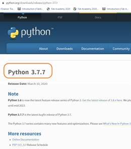
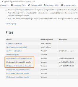
1. Python, from HERE. I used version 3.7.X as suggested by SP Fab lab coach, Mr. Rodney. I used Windows 64 bit but I want to install the version that's compatible for both 32 and 64 bit version. But for the purpose for exercise 12, I will install Python 2.7 32 bit because most of the libraries needed for my experiments are available for the older version of python.
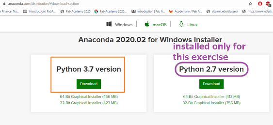
2. Anaconda, from HERE. Anaconda contains many useful libraries and also tools/IDE (Integrated Development Environment) for python language programming. Anaconda also comes with Phyton installed hence if you install Anaconda, then Phyton in step 1. becomes optional. Only for this exercise, I installed version 2.7 for the same reason mentioned above.
3.Vpython from HERE by typing in command prompt (for windows in search function type cmd) the command below:
pip install vpython
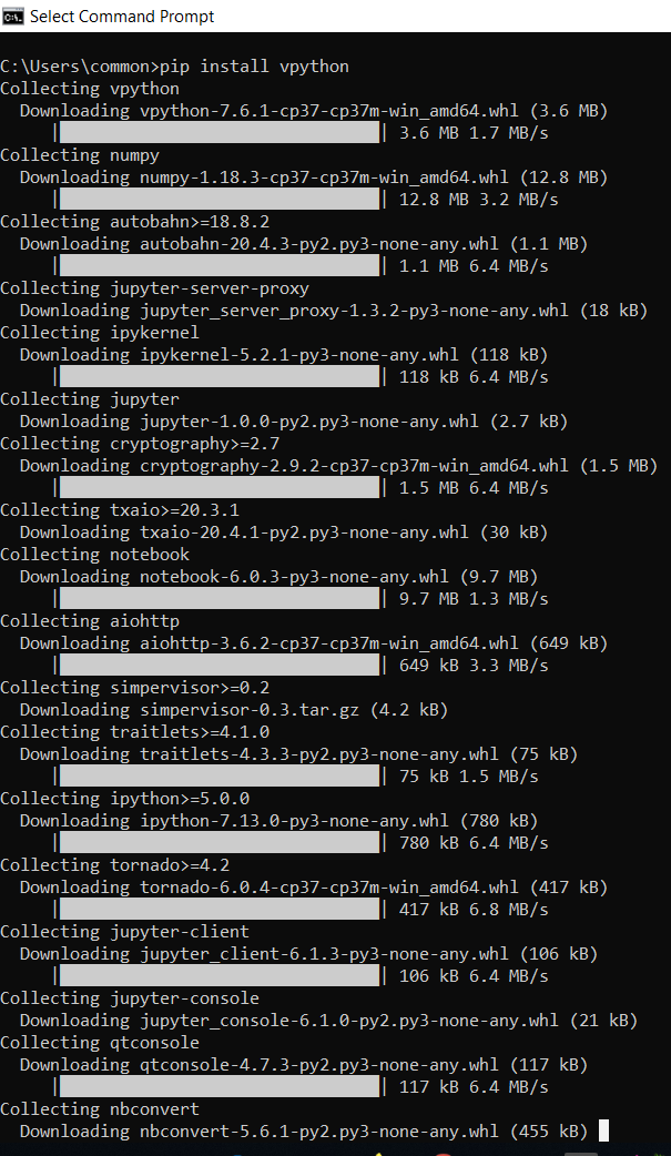
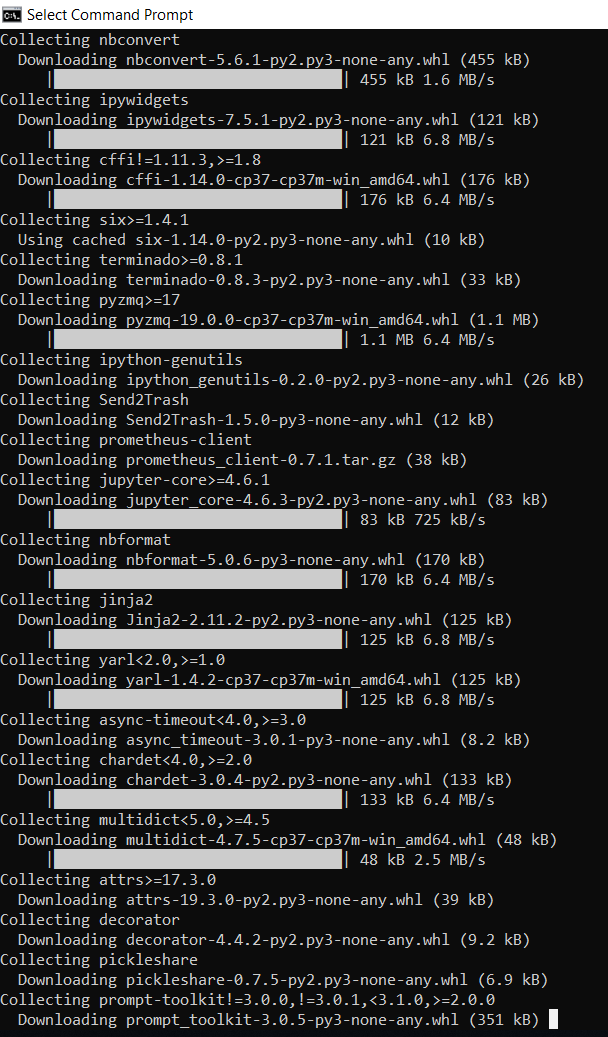
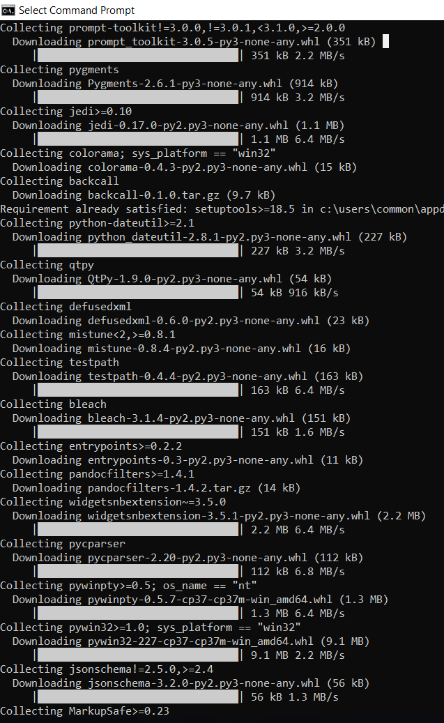
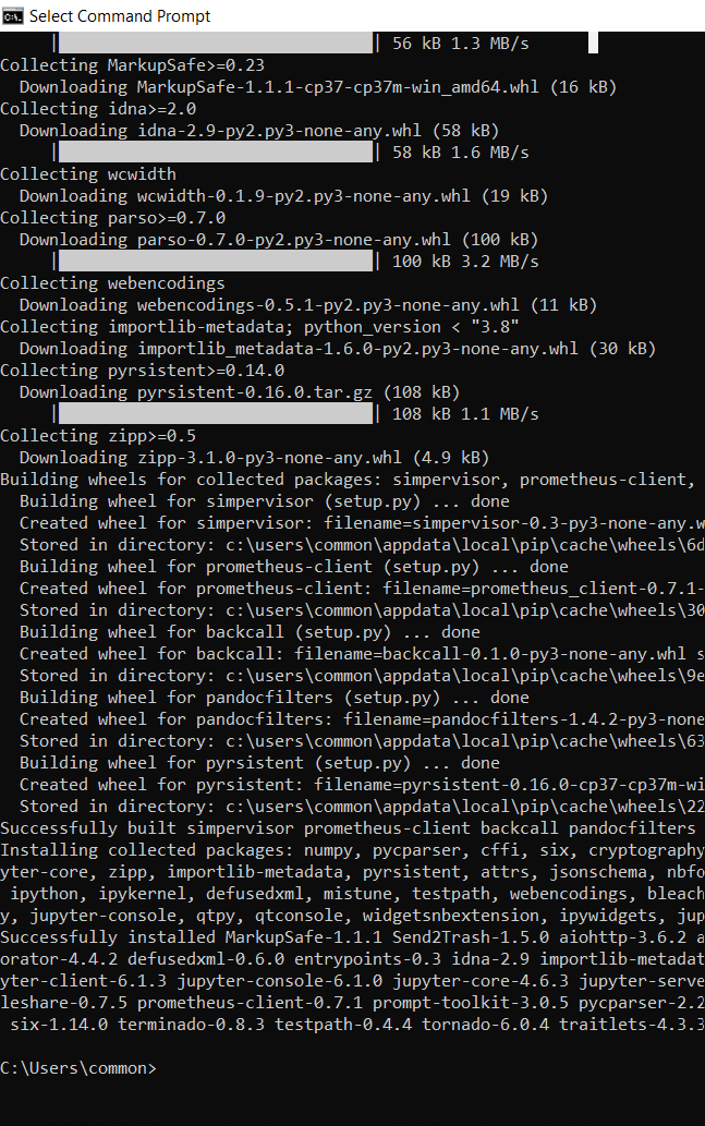
It will install many useful libraries and tools.
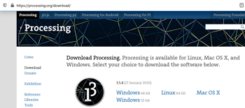
4. PROCESSING. The processing package can be downloaded from HERE.
I also found the below videos/tutorials very easy to understand for newbie in python programming and PROCESSING like me:
1. Corey Scafer.
2. Learn python in 4 hours.
3. PROCESSING REFERENCE
📱Compare and contrast tools for interface and application programming (Group assignment)
For this exercise, we decided to deep dive into:
1. Python language programming and toolkit.
2. Javascript.
3. Processing language and development environment.
The details can be seen HERE.
It's quite fun to see how the programme we have made appears as interactive and visually pleasing mode when input like mouse movement or mouse pressed are provided as input.
Write an application that interface a user with an input and/or output device that I have made🐍 💻
Since SP Fab Lab is closed due to COVID 19, I will experiment with ARDUINO UNO board for this exercise.
From mid June 2020, I have limited access to SP Fablab hence I started using the board that I have made for my final project that uses ATMega 328 MCU.
Hence, for this individual assignment, I did 2 attempts:
1. Ultrasonic sensor HC-SR04 (input) with Arduino board and PYTHON.
2. Ultrasonic sensor HC-SR04 (input) with My Board ATMega 328 and PROCESSING.
1. Ultrasonic Sensor HC-SR04 (input) with ARDUINO board and PYTHON🐍 💻
To do this, I use my work on exercise 9 using HC-SR04 and I refer to this tutorial.
I will attempt to create a GUI that display the distance between an object infront of the ultrasonic sensor real-time. The object and the sensor will be shown in the GUI as a 3D objects and it will move real-time as happened in real-world.
I will start by revisiting the work on exercise 9:
file used to execute the ultrasonic sensor as an input to meausure distance.
When the programme is run, the result can be seen in the below video:
The serial monitor in Arduino IDE is used to display the measured data. By using python, we will attempt to display this data using a more pleasing graphical user interface. In a gist, the data from arduino board will be transmitted to my laptop and using python, the data will be processed and displayed according to the code that I will create using python programmming language.
From the Arduino code, we need to take note the port com number (in my context is com 10) under the tools tab > port >
Besides that, we need to take note of the baude rate, which is 9600.
The echopin used in arduino board is PIN 9 and the triggerpin used is PIN 10.
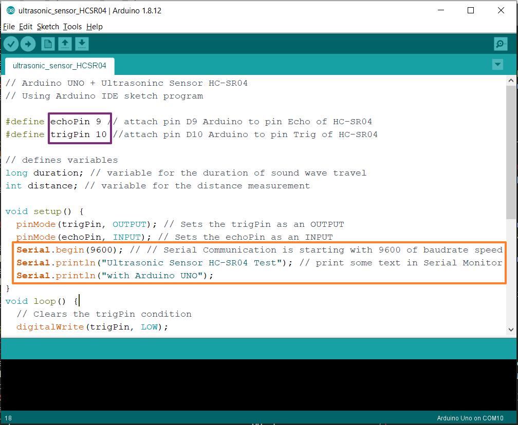
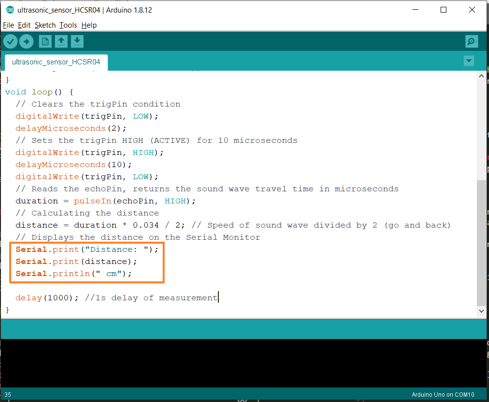
Very important to note is that since I will use Python to graphically present the data coming from the ultrasonic sensor, I want to simply send the distance measurement over the serial port of arduino board, and no words or anything else, just the raw distance measurement.
When I typed a
Serial.println();command in arduino IDE (as shown in the above images), I can read whatever is printed and shown in arduino ide serial monitor (as shown in the above video) into Python.
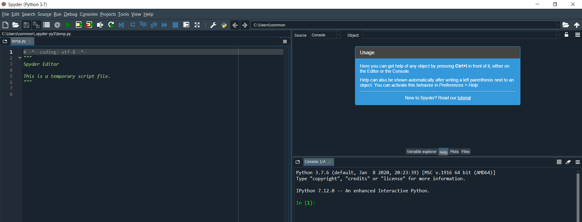
So using python, I must read that data send over the serial port. Let's start this by opening the text editor installed with Anaconda installation which is Spyder as shown below:
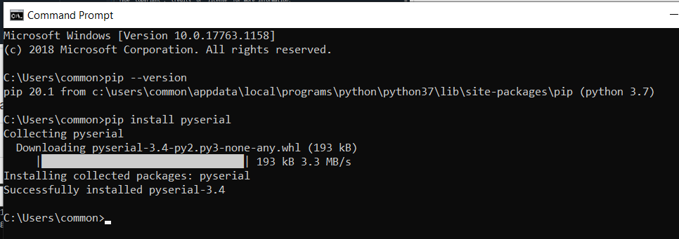
To read the data in the serial port, python requires library from pyserial.
Ensure that pip, wheel and setuptools are up to date by typing in command prompt (for windows in search function type cmd) the command below:
python -m pip install --upgrade pip setuptools wheel
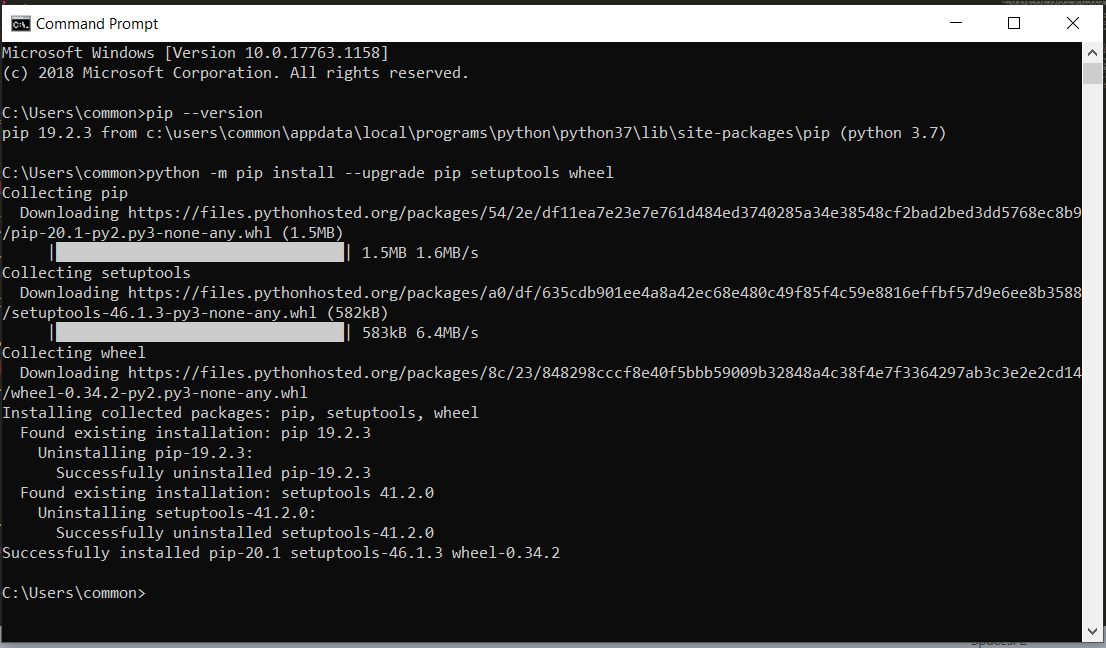
pip install pyserial
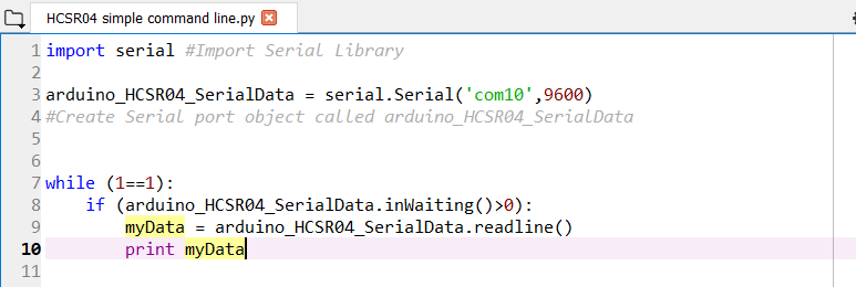
Now I am ready to type the code into the spyder text editor. To start I will create code to simply read the data from the serial port of arduino. Nothing fancy, just simple text line similar to serial monitor in Arduino IDE.
to download the python code .py file to read the data from serial port.
In this code, i created a serial object named "arduino_HCSR04_SerialData". The serial object is put under the while loop so that it will continuously read the data transmitted from serial port of arduino and print it into variable "myData". What is sent from serial port of Arduino is "Distance: x cm" and this data is shown exactly the same in the python console.
Below is the video when the python program is run and the code used
2. Ultrasonic Sensor HC-SR04 (input) with My Board ATMega 328 and PROCESSING 💻 🔊 ❄
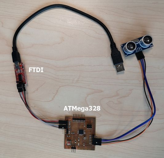
I started to use the board that I have made for MY FINAL PROJECT that uses ATMega328 and connect it to FTDI board to communicate using RX/TX (UART) serial communication so that the data can be transmitted to my laptop via USB.
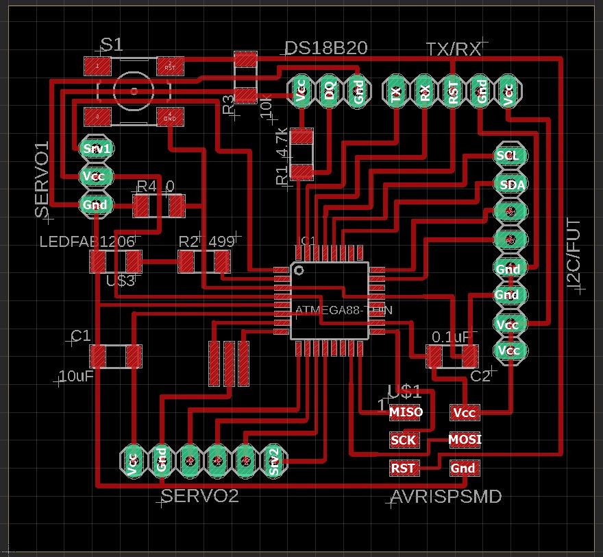
To recall, below is the schematic and board design that I have made.
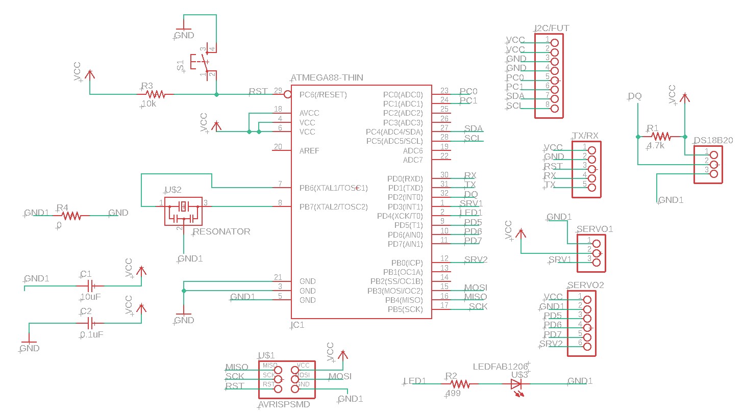
The ATMega 328 board is connected to an FTDI board to display the serial monitor by using the TX/RX pins on the board connected to the RX/TX pins of the FTDI board. At the same time the VCC and GND of ATMega 328 board is connected to the VCC and GND of FTDI board for power supply where the FTDI board will be connected to a PC via USB connection.
The TX pin is PD1 (pin 1 for Arduino) and RX pin is PD0 (pin 0 for Arduino) which are exactly the same as Arduino board.
I utilize 2 of the 5 extra pins that I have designed for the HC-SR04 pins, namely pin PD5 (pin 5 in Arduino) is connected to Echo and pin PD6 (pin 6 in Arduino) is connected to Trig.
Below image is how the ATMega 328 board, FTDI board and the HC-SR04 are connected.
to download the EAGLE schematic .sch file
to download the EAGLE board .brd file
to download the .png file of the traces.
to download the .png file of the board cutout.
I will be using similar arduino code as previous experiment, the changes are only the pins number for the RX/TX communication.
Note that my ATMega328 board uses the same Arduino pin number arrangement.
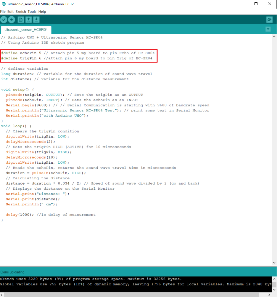
And I test it using Arduino IDE and show the serial monitor in the Arduino IDE.
It can be seen in the video below that the set-up was working properly were when the object infront of the sensor is moved hence the sensor will sense and measure the distance of the object.
To indicate the accuracy, I also put a ruler in between the sensor and object.
To create the GUI in PROCESSING, I started by creating a simple code to write using mouse cursor as shown in this page.
Arduino IDE was designed based on PROCESSING hence many similarities. For people who are new to GUI but have been using Arduino IDE, they will find PROCESSING easy and very familiar to use.
There are many similarities between Arduino IDE and PROCESSING Development Environment (DE) command line, for example:
Like Arduino, PROCESSING has a setup loop that is established by using:
void setup (){ code }
In Arduino IDE we use void loop where a certain function/command will continuously running. Since PROCESSING is more towards visual art, drawing shapes is often used and PROCESSING has a continuous loop where drawing is continuously performed that is established by using:
void draw () { code }
Similar to serial monitor in Arduino IDE, PROCESSING DE has canvas where the executed command will appear and user can determine the canvas size in pixels by using the below command:
size(width, height);
Below is the simple GUI PROCESSING programme that I created to read and display the distance measured by the HC-SR04 sensor.
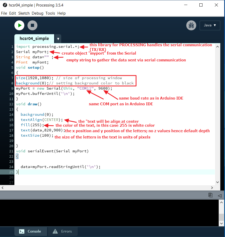
to download the PROCESSING code .pde file to read the data from serial port and display it into processing canvas.
I set the PROCESSING window pixel width and height to be the same as my laptop screen size (1920 x1080) with a background color of black.
I created an object called "myPort". This object is the data from serial port of Arduino COM11 and baud rate of 9600 which are the same configuration as the Arduino code in IDE.
Below is the video when the PROCESSING code is run.