Week 11: Output devices
This week we followed the output devices class (see video here)
This page is about the individual assignment.
- Abby Normal RGB led controlled by accelerometer
- Stepper motor
- RGB LED strip and sound generation
- Lessons learned
- Next steps
The production process for all the boards described below followed the same processes documented in week 6 (design with KiCAD, .png conversions, using mods) and week 4 (electronics production, milling PCB and soldering)
Abby Normal RGB led controlled by accelerometer
Because this week I was quite busy I decide to start with a simple example adapting the RGB LED board from Neil.
The board is quite simple and has as differences from previous examples a RGB LED with three pull-up resistors (note that the Blue input has a different R size) and a 5V regulator to allow the board to be powered by different generators. I later added two wires to connect PB3 and PB4 to two available pins on the header. 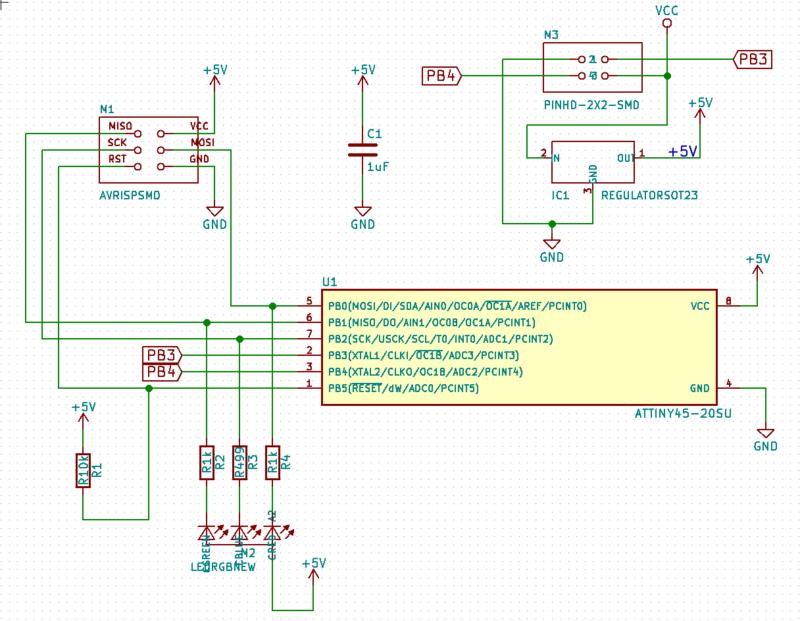
Here is the PCB 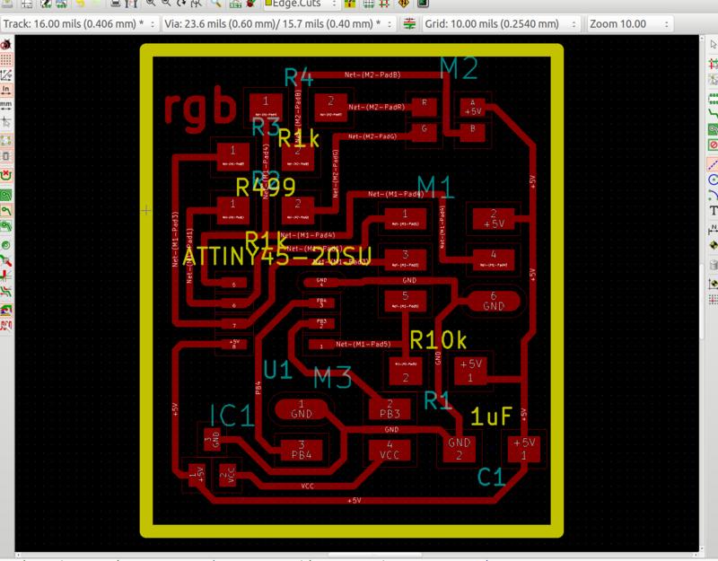
Download KiCAD project and GCode (.zip archive: KiCAD project, .png and .rml files)
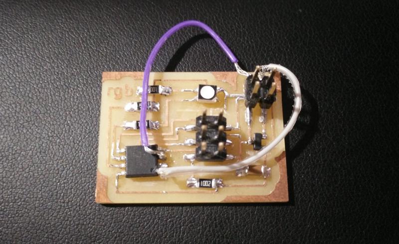
I realised after milling the board that I had made an error in the schema (the downloads above are correct) but didn’t want to rebuild the whole board in this case… I managed to fix this with a couple of jumper wires.
Se the fixed output board here:
I then decided to combine this board with the accelerometer input device that I created in week 10.
Each of the 3-axis of accelerometer drives one of the r-g-b color components of the LED.
The main code is a simple loop that reads from the acceleromenter, converts the value and uses then to control the RGB LED
int main(void) {
  unsigned char data[6];
  uint8_t red_value, green_value, blue_value;

  set_clock_divider_to_1();
  LED_pins_init();
  accel_init(data);

  while (1) {
    read_accel_data_sample(data)

    red_value = convert_acceleration_to_RGB_value(data[0], data[1]);
    green_value = convert_acceleration_to_RGB_value(data[2], data[3]);
    blue_value = convert_acceleration_to_RGB_value(data[4], data[5]);

    control_led_rgb_pwm(red_value, green_value, blue_value);
  }
}
That uses this function for controlling the LED PWM
void led_rgb_pwm_control(uint8_t red_value, uint8_t green_value, uint8_t blue_value)
{
    unsigned uint8_t count;
    for (count = 0; count < 255; ++count) {
      if (count <= red_value){
        red_on();
      } else{
        red_off();
      }

      if (count <= green_value){
        green_on();
      } else{
        green_off();
      }

      if (count <= blue_value){
        blue_on();
      } else{
        blue_off();
      }
      pwm_delay(1);
    }
}
In the video below the arduino board in only used as a power source for testing …I’m not cheating :)
Download C source code (.zip archive)
I’ve been told that the wiring looks a little bit like Frankestein so I decide to give to this project the “Abby Normal” name.
Stepper motor
I’ve been covering how to control a stepper motor via an Arduino CNC shield in the machine week assignment. You can find more details in the group assignment website in the “Using a stepper motor” section.
RGB LED strip and sound generation
For my final project I want to generate an syntetic heartbeat sound and control an RGB led strip to create light patterns. More details on this will be in my final project page for lights and sound control
Lessons learned
- How to control a single RGB LED with PWM (Pulse Width Modulation)
- How to use and regulate a DRV8825 stepper circuit.
- Driving a single motor is quite easy in code and we do not require a more complex CNC shield for this.
Next steps
- I would like to learn how to control a stepper motor without the CNC shield
- As part of my final project I plan to control an Adafruit DotStart pixels