Week Five
Make an in-circuit programmer by milling the PCB
PCB Milling
Milling PCB board is a prototyping technique used to manufacture circuits, it is cost effective and ecological but trades off with time efficiency, something that is not a problem on small scale production, but this process can’t be justified when scaling up to batches of around 100. Due to parts not being available to our lab we had to rework the ISP design, renamed FrankISP due to the Frankinstein-esk appearance.
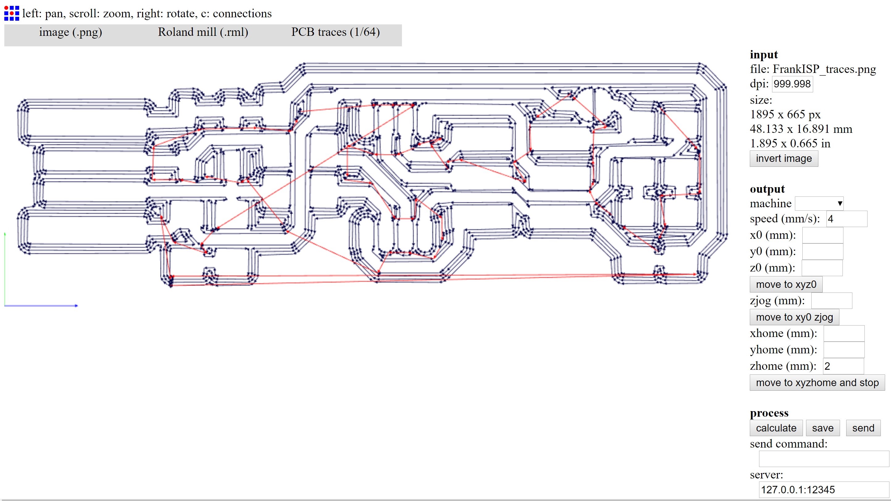
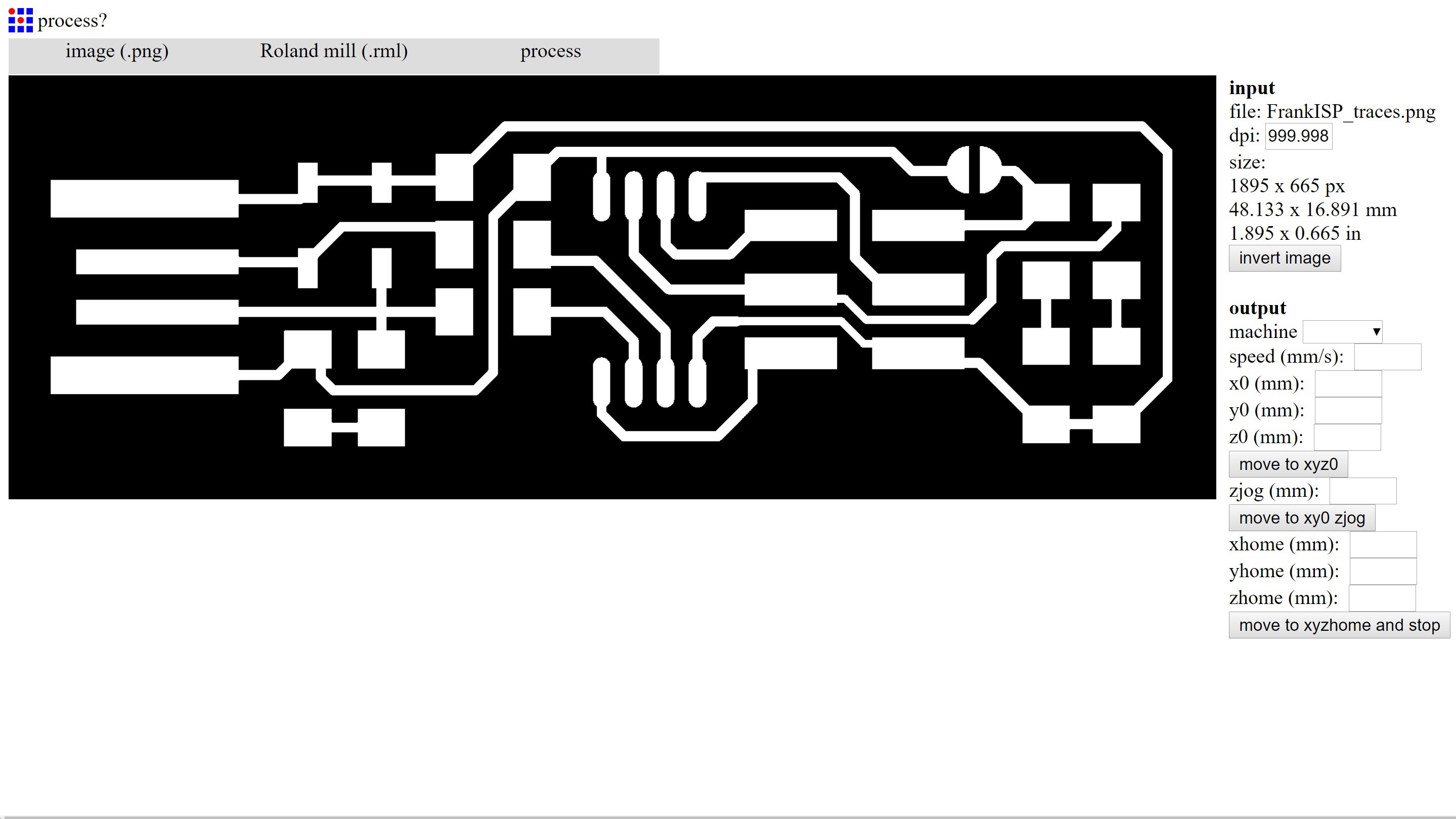
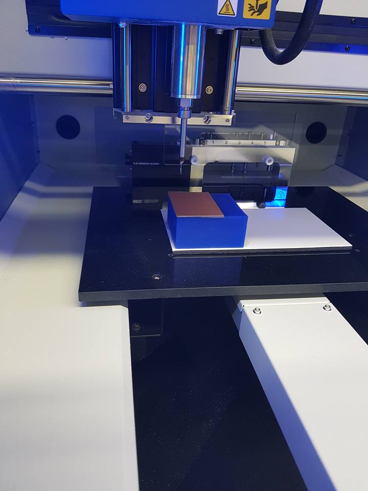
To prepare the program for the milling machine to run, we run a PNG file of our circuit through Fabmodules, something I will go into the future but for now, it basically generates a milling path for your machine converting the PNG into an RML. After this file is loaded we prep the machine, we crudely stick the PCB board onto the sacrificial wax block with double sided sticky tape and after selecting the correct milling tools begin to zero our XYZ into the origin for our program, this can be eyed in or we can use the sensor with adds a step as it is plugged in and placed onto the centre of the board. The practise has few steps and is relatively simple, another tool with a larger cutting head is selected to run the outline and release our circuit from the mother material.
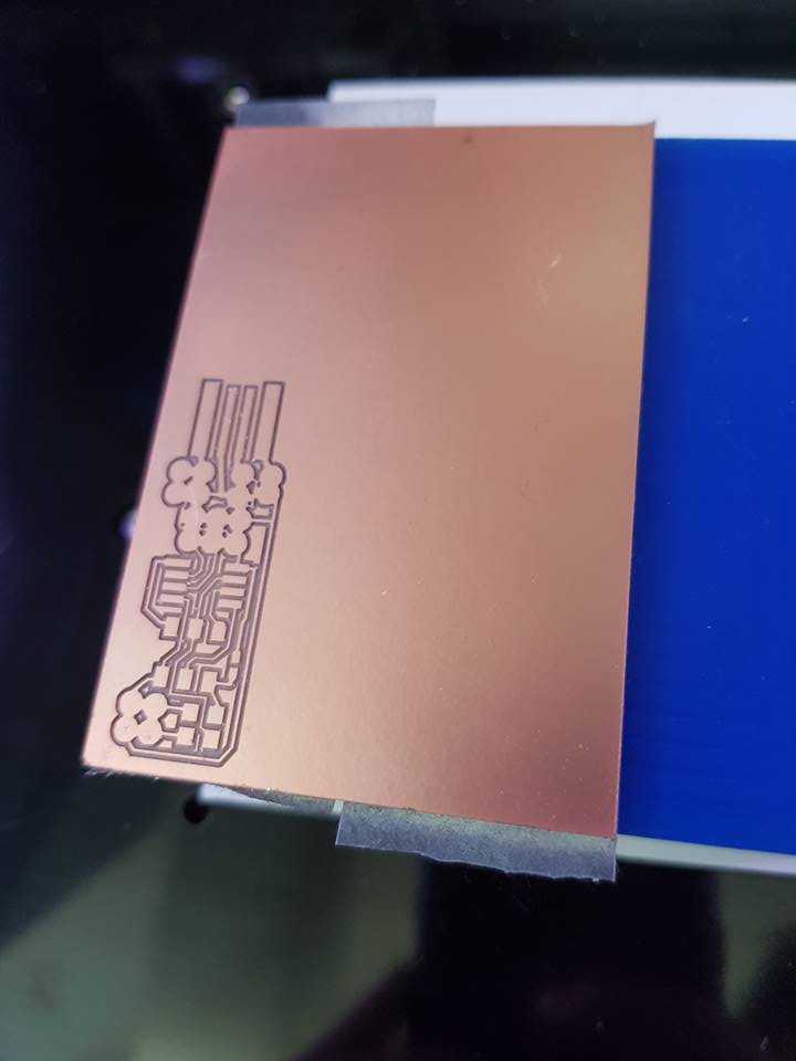
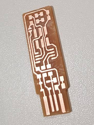
Due to the path selected the machine leaves excess copper plate behind which is removed before being prepared for soldering, at this stage I wash away the oxidized layer and any burs with wire wool.
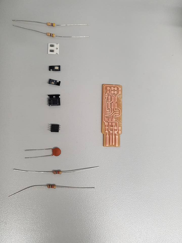
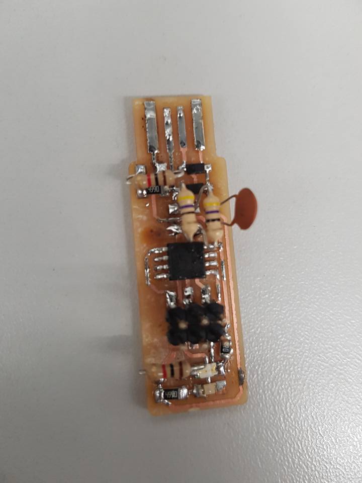
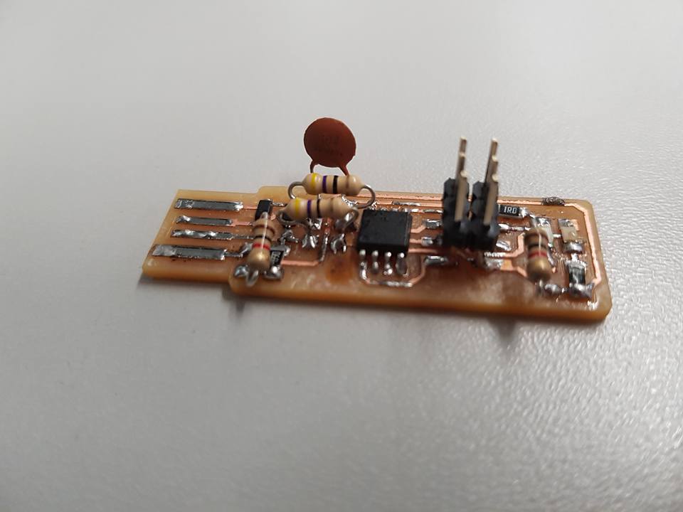
Parts are then soldered in place following our schema, with careful attention to the direction of flow to polarized parts, the circuit is checked for any shorts with a multi meter and passing that is ready to be coded.