Applications and Implications
Week 18
As classs assignment for this week I have to start thinking about my final project. My project is to design and built a telescope base. Around this stage will be added a GoTo system for tracking celestial objects. With the coming of Fab Academy 2018, I had to find a project that mean something to me: the building of the scope and adding a GoTo system was the perfect combination for a Fab Academician like me. What I've learned since then is how to make this dream comes true with the new skills sets that I've mastered since January.
The first version of this telescope will be vary basic: evaluating the initial design, the drivetrain and the electronics. Afterward, the first order of business will to complete the telescope, namely the Upper Optical Assembly, and adding the tube assembly holding the Upper Optical Assembly to the Lower Optical Assembly. Next point, I would like to add more features over time such as a fully automated tracking system, connected with the Stellarium software via Bluetooth.
What this project will do.
Create a Dobson telescope that is light, can go anywhere, nice to look at and easy to use. The Dobson telescope are made for enjoyment of the celestial bodies out there and are quite popular at star parties and public outreach. Recently and here, there's been an upsurge in popularity for these type of telescopes with big, 18", 20" and more, mirrors for observing deep sky objects. I want to create the basic recipe of parametric Dobson telescope mounts with digital control. Also, I want to create a new design that is my own and esthetically pleasing.
Who's done what beforehand?
This project is based on a book by Albert Highe with emphasis on building a telescope of any diameter with traditionnal tools that everyone can easily have. My project want to make a transfer from the traditionnal way of doing things to digital fabrication for the base and the telescope parts. I want to streamline the fabrication process and shave off as many kilos, or pounds, as possible for the whole telescope assembly with the use of 3D parametric software.
Because of the ease of contruction many people have made Dobson telescopes. Beside's the author's work, there seems to be very few people who took his approach and built a telescope following his directive. A Google search came up with models made by the author or his editor's website. It seems that I'm the first person making a Hihge telescope.
What will you design?
I will be designing everything from the Base, the Rocker Box, the Lower Optical Assembly and the Upper Optical Assembly. Beside this, I will design and test the electronics and the drivetrain.
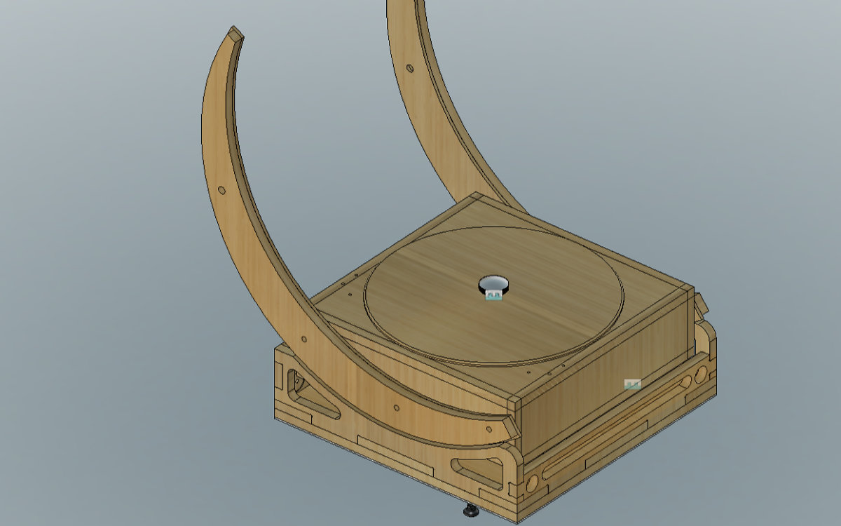
So far I've designed the base, the Rocker Box and the Lower Optical Assembly that needs some finishing before tackling the design of the motorization of the assembly. The main challenge of this project will be the motorization and guiding system.
Having seen a Lazy Susan used for another project inspired me to design a new base. Following this, a complete redesign of my own for the Rocker Box (dubbed MKII) followed. This will be done in July/August. Afterward will come the LOA and UOA.
What materials and components will be used?
The main material for this first prototype will be russian spruce, a plywood that cuts well, have a nice finish and no defaults on the wood. It's really a nice wood that I'm working with: the Rocker Box that I've done is proof enough. I will also include some other materials, namely nylon, teflon and Formica, plus hardware (nuts and bolts).
For the drivetrain, I will try Tough PLA made by Ultimaker for 3D printing the worm-gear system and motor bases.
How much will they cost?
The cost of the plywood is covered by the Fab Academy. The most expensive items are the motors (still unknown) and the drivers ($40 CAD for the two) to be covered by my own expenses. Also the electronics and the hardware. For this first phase, I have a budget of $200.00 US.
What parts and systems will be made?
Almost all the parts will be made: the Base, the Rocker Box and the Lower Optical Assembly are all milled from the plywood then glued or screwed. The electronics will be done at the lab. With the exception of the motors, I still have to nail down the design of the motorized parts of the system. My guess is that these part will be made of nylon or some other engineering plastic.
What processes will be used?
I will use the milling machine for the cutting of the Base, the Rocker Box and the Lower Optical Assembly. I will use Blender and Fusion 360 for the desing and printing of the worm-gear assembly plus the motor base and driveshafts. Laser cutting will be used for the living hinges that will be inside the Lower Optical Assembly and miscellenias. Eagle will be used for for electronic design. I still have to decide which software to use for the interface. The rest will require lots of elbow grease and sweat to integrate everything together.
What questions need to be answered?
Three questions remains: how to motorized the system, make the guiding system and develop the interface.
How will it be evaluated?
This is an easy question. A guiding system for a telescope is, after all, a system that controls two motors. What is the distinctive feature for a telescope guiding system is the precision of the tracking of the stars from the point of view of the Earth as it travels around the Sun: if it can't track, it's useless. I hope to built a tracking system that can track reasonnably well to prove the concept. If I pass this test, I will be happy.
Some thoughts
This is an ambitious program to say the least. As Neil noted during my final presentation, this is a project for many years. Still, I hope to realise a working prototype, a proof of concept, of what I have in mind. From this first iteration, continue to develop a telescope that is my own.
Bill of Material
The Bill of Material (BOM) for this project is not complete. But as a starting base, I will use the following:
- 1 - 1 Plywood Sheet
- 2 - 2 Stepper Motors (Digikey.ca)
- 3 - 2 Easy Drivers (Abra electronics)
- 4 - ATmega328 for the microcontroller
- 5 - Miscellaneous electronics parts like diodes, capacitors, resistances, crystal, jacks and limit switches
- 6 - My FasISP to program the board
- 7 - Electrical wires and cable managment
- 8 - Copper plate for pcb making
- 9 - Teflon, 5/16" for pads (was given to me)
- 10 - ¼" laminate strips
- 11 - Fiber Reinforced Plastic (or equivalent) for the bottom of the Rocker Box
- 12 - 5/8" - 18 bolts
- 13 - 5/8" - 18 T-Slots
- 14 - 3/8" washers
