Networking and Coomunication Assignment 13
Assignment 14
As I am going to do a Mouse in Final Project .. So I started thinking about how it will make my Communication on between them in bluetooth and sustain connection with Computer ..
So I am going to use Input Circuit , Output Circuit and Interfacing Week In this assignment to Intgerate Everything Together ..
So This Assignment will consists of these Techniques:
1) Configure 2 Bluetooth Together
2) SUstain the Communication between Computer , Input Circuit and The Output Circuit
This is my plan for this task :
1) Configuring the 2 Bluetooth
2) Testing with 2 Boards using Serial Commuication
3) Thinking about how to sustain all communication alive between 3 deviceson same channel
4) Coding
5) Testing
Task 1
This is what I made after a lot of searching
1- connect your arduino to the computer and run the Arduino IDE to bring up a blank sketsh
2- unplug the power source from the Arduino, and connect the SLAVE module to the Arduino
3- using the following configuration: RX to RX , TX to TX , GND to GND , VCC to 5V and EN to 3.3V
4- plug the power source to the Arduino and holding down to the reset button on the bluetooth module
5- now we can begin to configure the bluetooth module, run the Serial Monitor and there select “Both NL and CR”, as well as, “38400 baud” rate which is the default baud rate of the Bluetooth module. Now we are ready to send commands and their format is as following.

we need to write down this address as we will need it when configuring the master device.
Actually that’s all we need when configuring the slave device
6) connect the Master module to the Arduino, using the following configuration: RX to RX , TX to TX , GND to GND , VCC to 5V and EN to 3.3V
7)
to configure the other Bluetooth module as a master device. First we
will check the baud rate to make sure it’s the same 38400 as the
slave device. Then by typing “AT+ROLE=1” we will set the
Bluetooth module as a master device. After this using the
“AT+CMODE=0” we will set the connect mode to “fixed address”
and using the “AT+BIND=” command we will set the address of the
slave device that we previously wrote down.

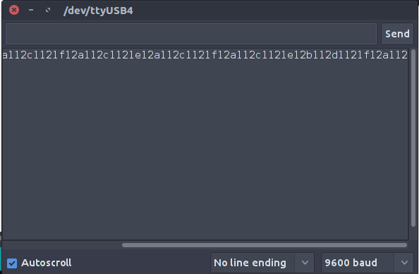
Task 2
This is Testing Bluetooth ..
I will Illustrate the Data in The Next Picuture in next task ..
Task 3
Now we need to Produce our communication system between the two boards and Laptop on same bus ..
First to maintain the data flow I make a Feedback Communication With each data slave Circuit " Output Circuit " Receive , Send to the master Circuit " Input Circuit " To send next Data ..
So 1 For Send Which Data it will send xor y or Btn , 2 For sending the value ..
So Here Slave controlling the master ..
Next Thing .. How To communicate data with My PC ..
As My sensor is not very accurate and Have a huge Noise .. SO i Determine to make it Digital By Making a average value that above is plus below is Minus So For x the Slave Circuit will Send on Same Bus a for Plus , b for minus and y is c,d and Button is e,f ..
That is it
Task 4
This is the code I used in Each Circuit and PC and With the GUI ..
First code for Input Circuit : ..
To Understand the Code Syntax and How I Wrote it .. You can Check my Embedded programming Assignment As I made There a full Illustrating for How to use Arduino and What is all Functions I used There ..
//#define F_CPU 20000000UL #includechar control(); #define BUTTON PA3 #define x PA2 #define y PA3 #define btn PA4 #define val 0 #define tx PA0 #define rx PA1 SoftwareSerial ser(0, 1); void setup() { // put your setup code here, to run once: pinMode(btn,INPUT); pinMode(x,INPUT); pinMode(y,INPUT); ser.begin(9600); } int casse=0; int casse1=0; void loop() { // put your main code here, to run repeatedly: while(!(control() == '1')) {} ser.print("b"); while(!(control() == '2')) {} ser.print(digitalRead(btn)); casse = analogRead(x); casse1 = analogRead(y); casse = map(casse ,0,1024,0,20); casse1 = map(casse1 , 0,1024,0,20); //delay(200); while(!(control() == '1')) {} ser.print("x"); while(!(control() == '2')) {} ser.print(casse); while(!(control() == '1')) {} ser.print("y"); while(!(control() == '2')) {} ser.print(casse1); } char control () { while (!ser.available()) { } return ser.read(); }
First code for Output Circuit : ..
To Understand the Code Syntax and How I Wrote it .. You can Check my Embedded programming Assignment As I made There a full Illustrating for How to use Arduino and What is all Functions I used There ..
#include#define x PA2 #define y PA3 #define btn PA4 #define tx PA0 #define rx PA1 SoftwareSerial ser(0, 1); void setup() { // put your setup code here, to run once: ser.begin(9600); pinMode(x,OUTPUT); pinMode(y,OUTPUT); pinMode(btn,OUTPUT); } void loop() { // put your main code here, to run repeatedly: ser.print("1"); if (ser.available()) { char val = ser.read(); if (val == 'x') { ser.print("2"); while(1) if (ser.available()) { int mov = (ser.parseInt()); if(calc(mov)==1) ser.print("a"); else ser.print("b"); delay(10); ser.print("1"); if (mov > 5) {digitalWrite(x,HIGH); break; } else { digitalWrite(x,LOW); break; } } } else if (val == 'y') { ser.print("2"); while(1) if (ser.available()) { int mov = (ser.parseInt()); if(calc(mov)==1) ser.print("c"); else ser.print("d"); delay(10); ser.print("1"); if (mov > 5) {digitalWrite(y,HIGH); break; } else { digitalWrite(y,LOW); break; } } } else if (val == 'b') { ser.print("2"); while(1) if (ser.available()) { int mov = (ser.parseInt()); ser.print("1"); if (mov == 1 ) {digitalWrite(btn,HIGH); ser.print("e"); break; } else { ser.print("f"); digitalWrite(btn,LOW); break; } } } } delay(100); } int calc (int mov) { if(mov>6) return 0; else return 1; }
Third code for Python On Laptop : ..
 x=100
y=100
import time
import pyautogui
import serial
ser = serial.Serial('/dev/ttyUSB0')
kk=0
line1=0
line2=0
line3=0
while 1 :
	line = ser.read()
	print line
	print "---------"
	if line == 'a' :

		if(x< 6<00):
			x=x+10
	elif line == 'b' :
		if(x>0):

			x=x-10
	elif line == 'c' :

		if(y< 600):
			y=y+10
	elif line == 'd' :
		if(y>0):

			y=y-10
	if line == 'e' :
		pyautogui.click(x,y)
	elif line == 'f' :
		print "nothing"

	pyautogui.moveTo(x, y)
	#time.sleep(1);
	#print "btn = " , line1 , " x = " ,  line2 , " y = " , line3
Fourth code for Processing : ..
  /**
 * Simple Read
 *
 * Read data from the serial port and change the color of a rectangle
 * when a switch connected to a Wiring or Arduino board is pressed and released.
 * This example works with the Wiring / Arduino program that follows below.
 */


import processing.serial.*;

Serial myPort;  // Create object from Serial class
char val;      // Data received from the serial port
int x = 100, y=100 , btn=0;

void setup()
{
  size(200, 200);
  // I know that the first port in the serial list on my mac
  // is always my  FTDI adaptor, so I open Serial.list()[0].
  // On Windows machines, this generally opens COM1.
  // Open whatever port is the one you're using.
  String portName = Serial.list()[0];
  myPort = new Serial(this, "/dev/ttyUSB0", 9600);
}

void draw()
{
  if ( myPort.available() > 0) {  // If data is available,
    val = myPort.readChar();         // read it and store it in val
    if (val == 'a')
  {
    if(x<300)
    x=x+50;
  }

   else if (val == 'b')
  {

    if(x<50)
    x=x+50;
  }
   else if (val == 'c')
  {

    if(y<300)
    y=y+50;
  }
   else if (val == 'd')
  {

    if(x>50)
    x=x-50;
  }
   else if (val == 'e')
  {
      btn=1;
  }
   else if (val == 'f')
  {
      btn=0;
  }
  }


  background(x);             // Set background to white
  if (btn == 1) {              // If the serial value is 0,
    fill(y);                   // set fill to black
  }
  else {                       // If the serial value is not 0,
    fill(204-y);                 // set fill to light gray
  }
  rect(50, 50, 100, 100);
}
Task 4
Testing Everything Together
Everything Working Together
