Output Devices Assignment 12
Assignment 12
As I am going to do a Mouse in Final Project .. So I started thinking about how it will looks like my output circuit ..
I am going to need a bluetooth in the circuit to communicate Communication assingment at future with the input assignment I made before to read the Analog joystic Data ..
Then I will need LEDs as Indicators for The system that is receiving the Data Correctly from the input circuit and Show it on the LEDs and a LED for bluetooth to show that there are a connection .. That is Connected to State pin in the Bluetooth
And FTDI and ISP to can Program and send Data to Computer through serial to start moving the Mouse and Circuit interact with the Interface program ..
So It will consists of these :
BOM :
Main Board As a Block
1) Attiny 44
2) Res 10k
3) Cap 10UF
4) ISP Connector
5) FTDI Connector
Then I Added my special Circuit Component :
1) Bluetooth Pin Header
2) 4 LEDs
3) 4 Res 490
4) Bluetooth HC-05
You can Find here all component I used with links where to buy it and it is name to can find datasheet ..
Component | Amount | Price for 1 | Link |
Res 10K | 2 | $0.05 | |
Res 499 | 4 | $0.05 | |
Capacitor 10UF | 2 | $0.1 | |
RED LEDs | 4 | $0.25 | |
FTDI Header | 1 | $0.25 | |
HC-05 Bluetooth Module | 2 | $17 | |
ATTINY44A-SSU-ND | 2 | £0.596 | |
ISP Pin Header | 2 | $0.83 | |
Female Pin Header | 17 Pin | $0.1 | |
Analog Joystic | 1 | $2 |
This is my plan for this task :
1) Design
2) Fabricate
3) Soldering
4) Coding
5) Testing
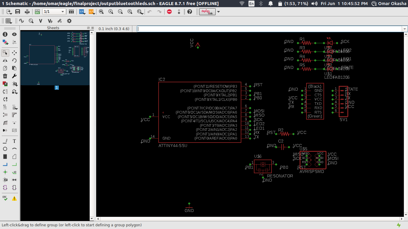
Task 1 For Designing I followed the same Steps in Electronics Design Week
As In Input Devices I used Design Blocks ..
Important Informations about the SMD LEDs .. the Negative side of it you will Find a Green line on a side that is the negative side .. and you need to take on Consideration this in the design .. Also LEDs need a Resistance that is 499 OHm to can deliver to it the amper that it is want .. you can found datasheet Here
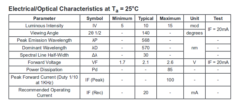
you can find here Forward Voltage Which is Important to calculate the Resistance that we need to put beside the LED ..
you can Find that the Maximum is 2.6 Volt and current 0.02 A ..
So We need to calculate the Resistance ..
5V - 2.6v = 2.4V
Then the Resistance will be 2.4/0.02
Which will be 120 ohm ..
also Take in Consideration the arrange of the Pins of the Bluetooth to can deliver power and read data right .. and take care of the Orientation you will use ..
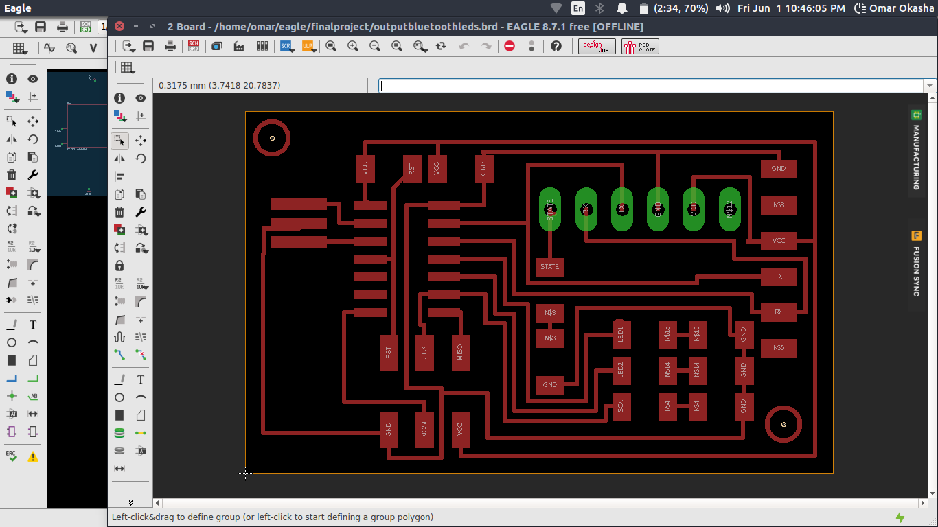
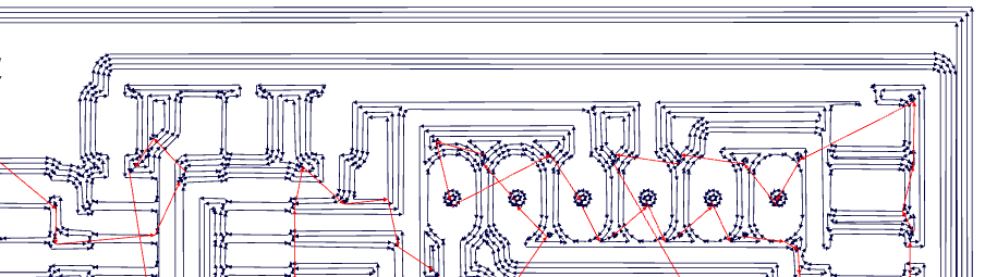
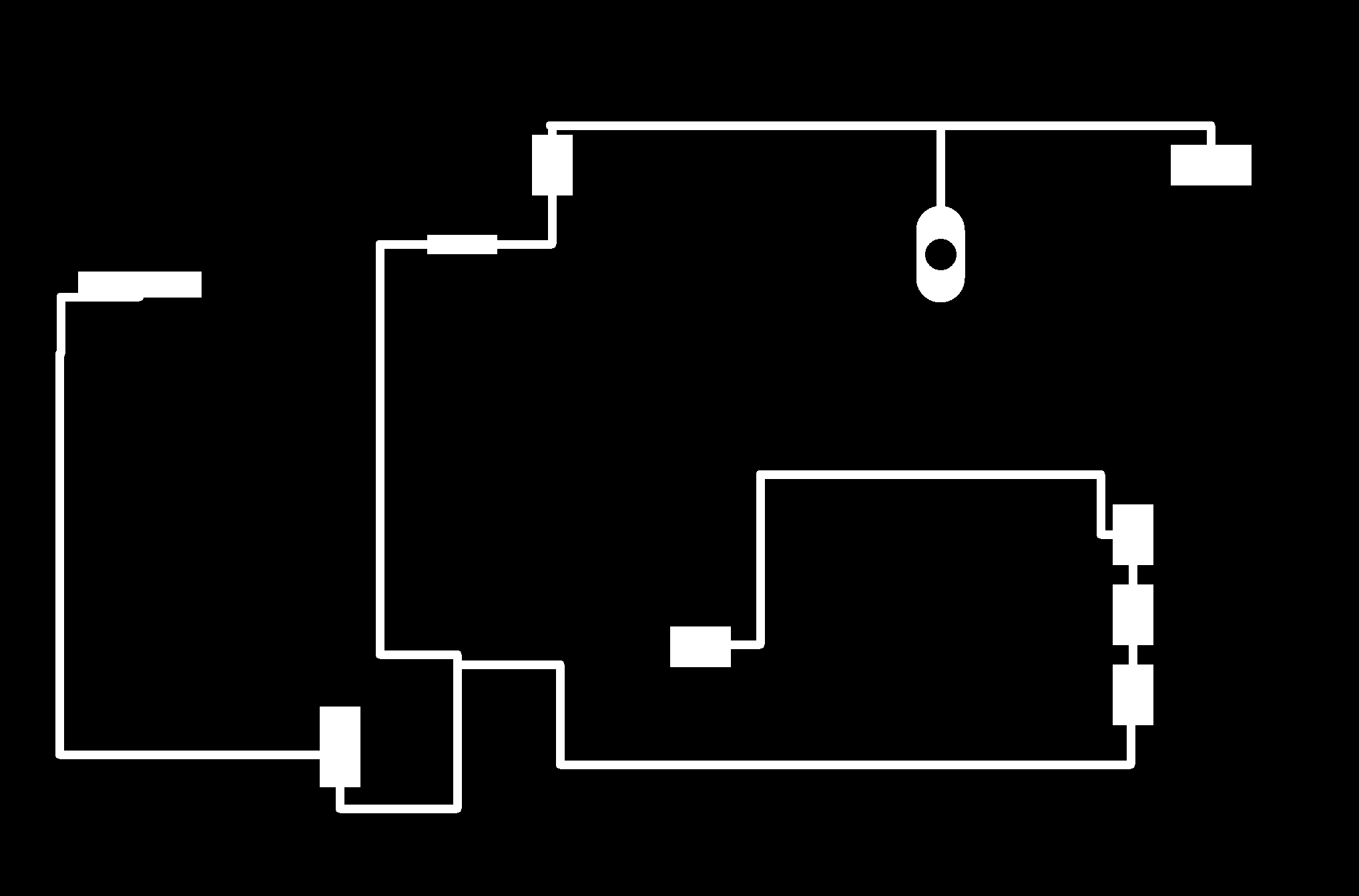
Then I start Building on it .. and this is the result ..
Task 2
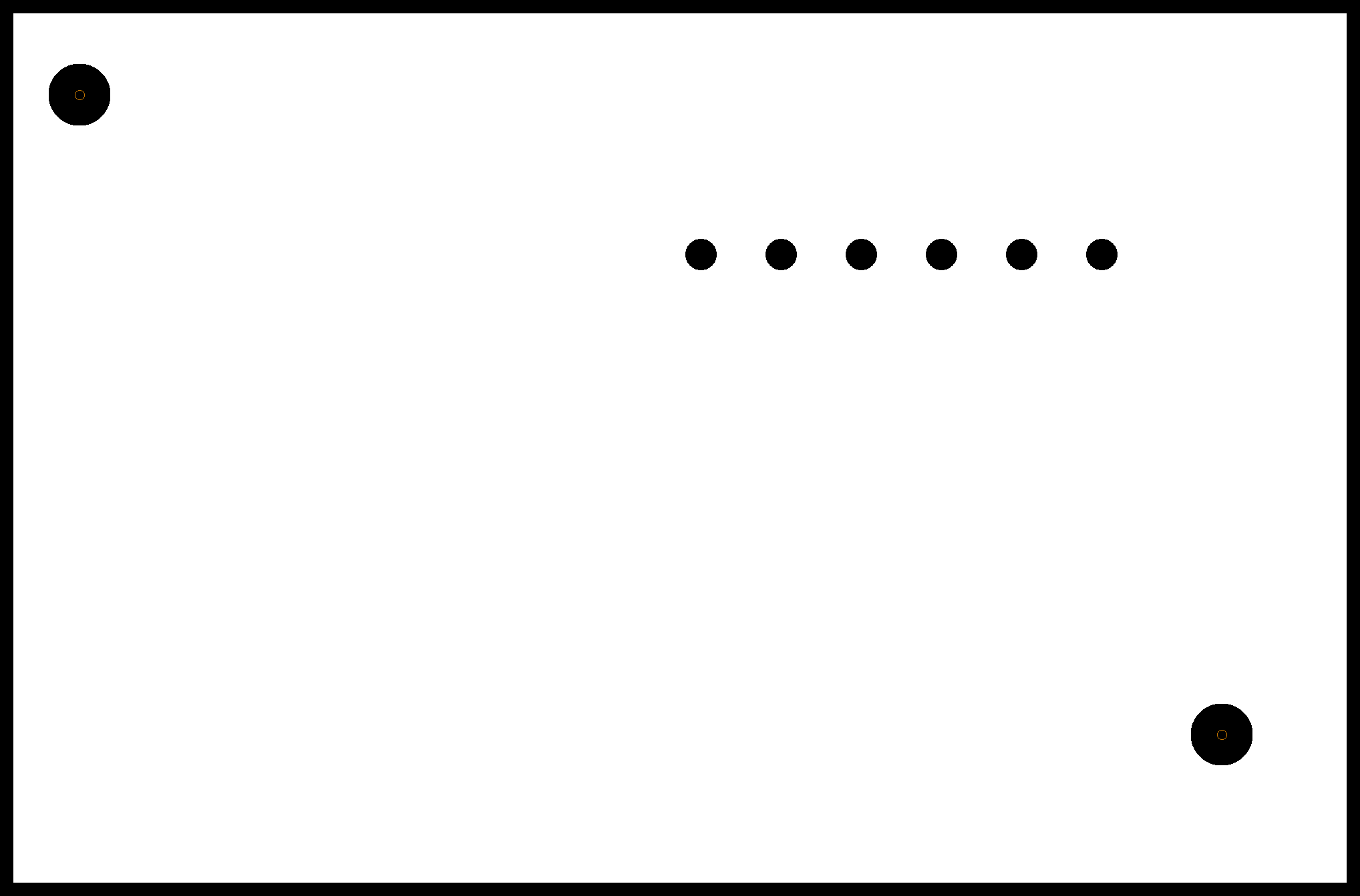
Here are the Files to Be fabricated on CNC ..
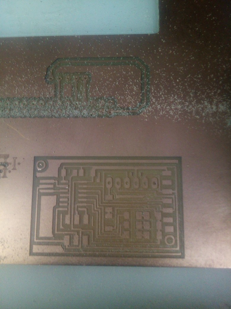
For Fabricationg I followed the same Steps in Electronics Production Week

But I didnt notice this while I was making it on Fab Modules .. That there are a short circuit .. and this Short circuit happened because of I had in the design a circle because of un finished trace that I didnt See that above my trace that makes fab modules see them as 1 Trace and Didnt figure out that they are 2 Traces ..
the other issue that I need to take in consideration next is to leave a little more space between traces as I wanted to make my PCbs Design Perfectly Design with the Smallest Size and Traces ..
As A Credit For My Instructor Hagag He Had a Great idea Like you will see at the picture that he removed all the lines and let just the ground .. and this what happen .. the machine removed the short circuit ..
This is the error
Task 3
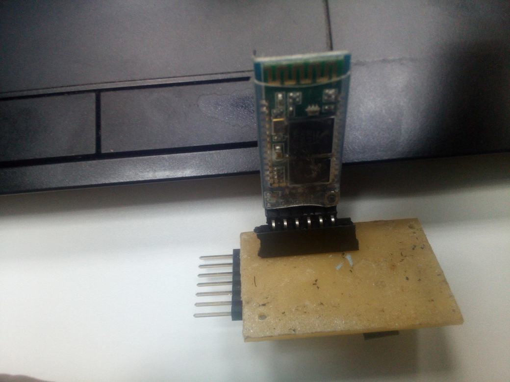
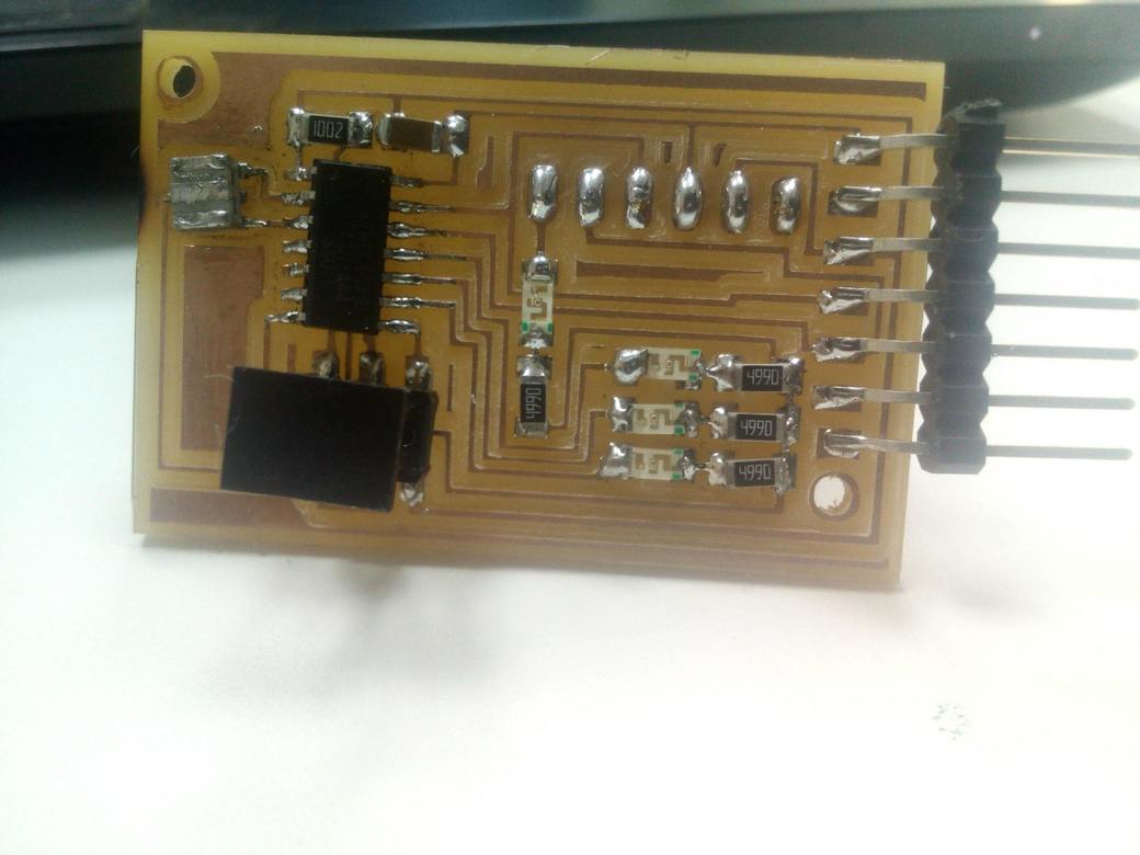
Then This is How it looks like my Final Output PCB ..
This how it looks like with Component
Task 4
This is the code i used for the output circuit ... Which read the data coming from the the Input circuit and Test it with LEDs and Pass it To the FTDI to Send it to the Connected Computer .
Here the PCB have 4 LEDs ..
2 LEDs for x axis and y axis
1 LED for Push Button state
1 LED For the connection of the Bluetooth
A Important note about the code ..
I Transform the Analog Readings to Digital Because of the Noise ..
To Understand the Code Syntax and How I Wrote it .. You can Check my Embedded programming Assignment As I made There a full Illustrating for How to use Arduino and What is all Functions I used There ..
    #include ‹SoftwareSerial.h›


#define x PA2
#define y PA3
#define btn PA4

#define tx PA0
#define rx PA1
SoftwareSerial ser(rx, tx);
void setup() {
  // put your setup code here, to run once:

ser.begin(9600);
pinMode(x,OUTPUT);
pinMode(y,OUTPUT);
pinMode(btn,OUTPUT);
}

void loop() {
  // put your main code here, to run repeatedly:

  if (ser.available()) {
     char val = ser.read();
     if (val == 'x')
     {
      if (ser.available()) {
         int mov =  (ser.parseInt());
         if (mov > 5)
         digitalWrite(x,HIGH);
         else
         digitalWrite(x,LOW);
      }
     }
     else if (val == 'y')
     {
      if (ser.available()) {
         int mov =  (ser.parseInt());
         if (mov > 5)
         digitalWrite(y,HIGH);
         else
         digitalWrite(y,LOW);
      }
     }
      else if (val == 'b')
     {
      if (ser.available()) {
         int mov =  (ser.parseInt());
         if (mov ==1)
         digitalWrite(btn,HIGH);
         else
         digitalWrite(btn,LOW);
      }


     }
  }

  delay(500);
}
Task 5
This is The working Circuit With the live data