Choosing Microcontrollers
We could use a commercial board to talk to the machine. We chose to use Arduino Mega 2560 with RAMPS 1.4 shield.
We use two A4988 stepper driver boards to control the two stepper motors in our machine.
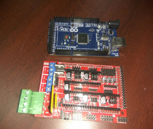
Ramps (Source) and Arduino Mega (Source)
Arduino Mega(Source)
The Arduino MEGA ADK is a microcontroller board based on the ATmega2560. It has a USB host interface to connect with computers.It has 54 digital input/output pins (of which 15 can be used as PWM outputs), 16 analog inputs, 4 UARTs (hardware serial ports), a 16 MHz crystal oscillator, a USB connection, a power jack, an ICSP header, and a reset button
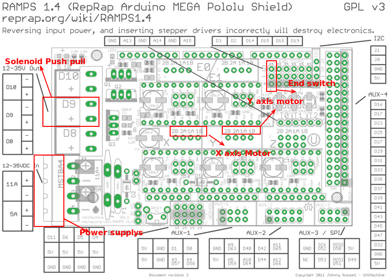
Ramps14(Source)
Ramps is short for reprap Arduino mega pololu shield, it is mainly designed for the purpose of using pololu stepper driven board (similar to 4988 driven board). Ramps can only work when connected to its mother board Mega 2560 and 4988/DRV8825
Source of the above detailsA4988 Stepper Driver
A4988 microstepping bipolar stepper motor adjustable current limiting, over-current and over-temperature protection, and five different microstep resolutions (down to 1/16-step).
It operates from 8 V to 35 V and can deliver up to approximately 1 A per phase without a heat sink.
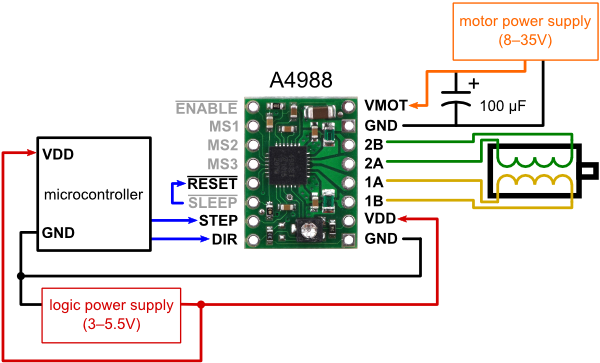
A4988 Stepper Driver
Source
Major features of A4988 stepper driver is Simple step and direction control interface, Five different step resolutions: full-step, half-step, quarter-step, eighth-step, and sixteenth-step.
Adjustable current control lets you set the maximum current output with a potentiometer, which lets you use voltages above your stepper motor’s rated voltage to achieve higher step rates.
Connection Diagram
Source
Choosing the end effector to be attached to the printer head
We needed an end effector to punch holes in a regular paper,the standard Braille holes have to be close to 1.44mm diameter size.
After the first Solenoid we purchased was a failure because it had no power to embose the holes, i decided to use Servo motor to make the embosing action with a tool head attached to the Servo shaft.
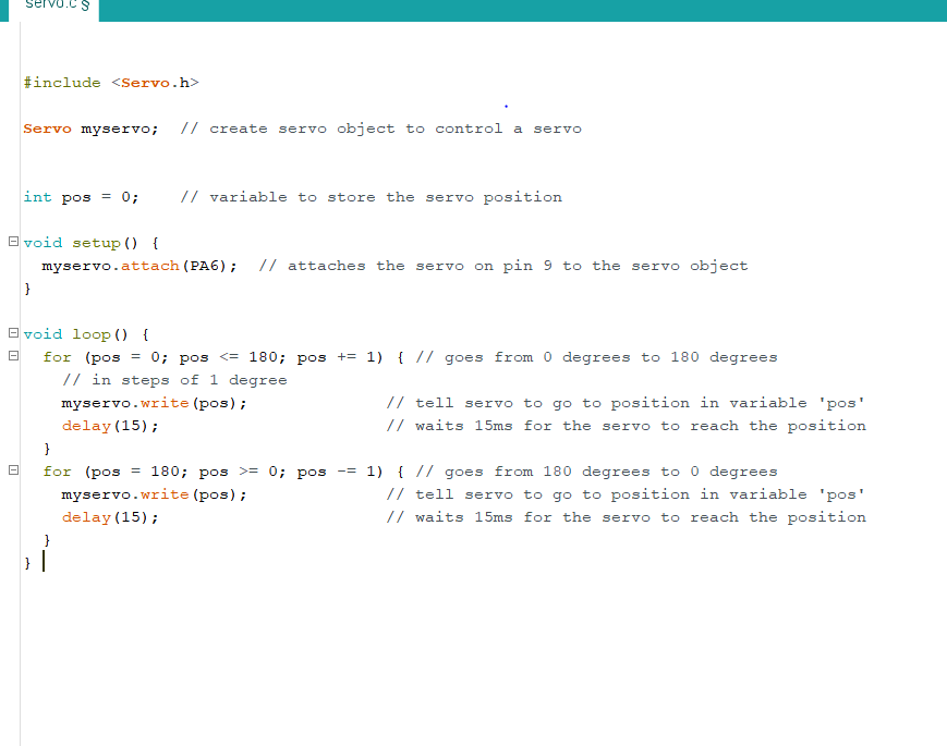
Download Program file for servo
We needed to test the stepper motor and how much steps it takes to complete one revolution. We connected the ramps board to Arduino mega and connect the A4998 driver to X part of ramps 14 board.N ext connect all the 4 pins named 2A, 2B, 1A & 1B to the stepper motor. According to the schematic diagram, we find that stepping and direction pin of x is connected to 54 and 55 pins of mega and enable pin is connected to 38.
   #define X_STEP_PIN       54
#define X_DIR_PIN          55
#define X_ENABLE_PIN       38

char data = 0; //byte to receive and check data from computer
void setup() {

  Serial.begin(9600);//Start the Serial port.
  pinMode(X_STEP_PIN   , OUTPUT);
  pinMode(X_DIR_PIN     , OUTPUT);
  pinMode(X_ENABLE_PIN      , OUTPUT);

}
void loop()
{
  if (Serial.available())
  { //if there is data on the Serial buffer
    while (Serial.available() > 0)
    { //continues reading the values on the buffer.
      data = Serial.read();
      Serial.print(data);
      if (data == '1') {
        forward(200); // if i recieves make single rotoation clock wise
      }
       if (data == '0') {
          backward(200);  // if i recieves make single rotoation anti clock wise

        }

      }
    }
  }
  void forward(int number) {
    digitalWrite(X_DIR_PIN    , HIGH);
    for (int i = 0; i <= number; i++)
    {
      digitalWrite(X_STEP_PIN    , HIGH);
      _delay_us(500);
      digitalWrite(X_STEP_PIN    , LOW);
      _delay_us(500);
    }
  }
  void backward(int number) {
    digitalWrite(X_DIR_PIN    , LOW);
    for (int i = 0; i <= number; i++)
    {
      digitalWrite(X_STEP_PIN    , HIGH);
      _delay_us(500);
      digitalWrite(X_STEP_PIN    , LOW);
      _delay_us(500);
    }
  }
Amith wrote a program in which , when if we send 1 through serial monitor it rotates one revolution and if we send 0 it roates backward.
Number of steps per revolution should be 200 by default but the program was not working.
This was because all stepper drivers A4988 come from china are in the 1 /16 microstepping.
Which meant the total No.of steps required for 360 deg rotation = 200*16 = 3200. And when we changed the steps 200 to 3200 it worked.
As said earlier, the first solenoid didnt have enough power to make holes in paper so we took another option to use a servo motor . Our idea was to connect a pen/tool to the servo motor and move up and down it makes holes.
Ramps14 have capacity to connect 4 servo motors , So we connected the servo motor and the stepper motor and wrote a code to control all these using serially
Code for running Stepper forward ( x axis -which head moves )
        void forward(int number) {
          digitalWrite(X_DIR_PIN    , HIGH);  // makes the motor direction in forward
          for (int i = 0; i <= number; i++)
          {
            digitalWrite(X_STEP_PIN    , HIGH);
            _delay_us(500);
            digitalWrite(X_STEP_PIN    , LOW);
            _delay_us(500);
          }
        }
Code for running Stepper backward( x axis -which head moves )
        void forward(int number) {
          digitalWrite(X_DIR_PIN    , LOW); // makes the motor direction backward
          for (int i = 0; i <= number; i++)
          {
            digitalWrite(X_STEP_PIN    , HIGH);
            _delay_us(500);
            digitalWrite(X_STEP_PIN    , LOW);
            _delay_us(500);
          }
        }
Code for running controlling servo to make holes ( x axis -which head moves )
        void braille(void){
                 myservo.write(0);
                  delay(100);
                 myservo.write(50);First paper drwaing : How printer looks
}
Code for running Stepper forward ( Y axis -which paper roller connected )
          void forward(int number) {
            digitalWrite(Y_DIR_PIN    , HIGH);   // makes motor direction forward
            for (int i = 0; i <= number; i++)
            {
              digitalWrite(Y_STEP_PIN    , HIGH);
              _delay_us(500);
              digitalWrite(Y_STEP_PIN    , LOW);
              _delay_us(500);
            }
          }
Function to control the actions
        void loop()
            {
                  if(Serial.available())
                     {              //if there is data on the Serial buffer
                while(Serial.available()>0)
                     {               //continues reading the values on the buffer.
                   data=Serial.read();
                   Serial.print(data);
                   if(data=='1')
                   {
                        braille();//if a one was received, makes a dot.
                       forward(3200);
                    }

                  if(data=='0'){
                     forward(3200);// if a zero was received just advances.
                       }
               if(data=='3'){//if a "3" was received, pull the paper to begin a new line.
                backward(3200);//return the car.
                       }
                  }
               }
            }
That is when Our instructor Yadhu bought the good solenoid and gave it to us, so we are now again on track.
The power of this one was quiet enogh to embose the holes.
Then we have to calculate the movement of motors.
First we connected X-axis stepper motor to the ramps.
A small mark was made on the bottom of the head and we rotated stepper motor for one cycle and then marked on the bottom of head again.
The distance between the two marks was a distance of 31mm, ie; for one cycle of rotation of the stepper motor(3200 steps) the head goes the distance of 31mm
After completing this, We should calcute the Y axis part, where the paper should move forward for printing.
We used the paper rod from old printer with rubber bushes to help paper to move forward and backward .
Then we measured diameter of the rubber bush covering, it was 11.8mm. So for 1 revolution of stepper motor rod covers a distance of 22/7*11.8mm = 37.05mm
After making these calculations we found that for 1mm movement of the X-axis head we need a step of 104 and for the Y-axis 1mm movement we need a step of 86.
We referred the Instructables website for some CNC machine tutorials and from there we got the idea of controlling the stepper motor using some open source firmware.
On searching and we found the Marlin firmware, which is good and useful.
Now using a G code file, we can control the printer.
Marlin firmware
A firmware is a permanent software programmed into a read-only memory. Marlin firmware is program that designed and developed for making 3D printers using Ramps board.
Firmware is the link between software and hardware, it interprets commands from the G code file and controls the motion accordingly.
We could use marlin firmware for any machines if we made some changes.
We need to run two stepper motor and control on solenoid push-pull using G code.
Marlin firmware Download link http://marlinfw.org/meta/download/
After downloading the firmware, open the file Configuration.h in the Marlin folder and Set the communication speed:
#define BAUDRATE 115200
The serial communication speed as 115200 gives a balance between speed and stability.
We need to configure the End stops for all the edit functions are making on Configuration.h file.
The main aim of end stops is to find the origin of the head.
End stops are switches that trigger before an axis reaches its limit, It will prevent the head from trying to move out of its frame.
The printer also uses end stops as a reference position.
The Marlin firmware allows to configure each limit switch individually. We made our end stop is on the right side of the machine.
#define X_MIN_ENDSTOP_INVERTING false // set to true to invert the logic of the endstop
The total number of axis which is 2
#define NUM_AXIS 2
The stepper motor receives step by step moving command from the controller.
DEFAULT_AXIS_STEPS_PER_UNIT {X,Y,Z,E1}
The controller needs to know the steps per mm ratio for sending the appropriate steps to reach the required distance.
How many steps are needed to move an axis by 1 mm. here we use the calculations find in above
#define DEFAULT_AXIS_STEPS_PER_UNIT { 104, 86, 4000, 500 } //104 stands for 1mm moement in x axis number of steps is 104 and for y axis 1mm movement steps is 86 other values are not usefull to us
Send the firmware to the 3D Printer: after verify the marlin.ino in marlin folder and upload that code to arduino mega and after that Power up the machine and open prointerface in your Pc and connect arduino to pc using usb cable.
Click to connect the machine and move X axis a little amount like +1 or +10 mm. after that we found that its working.
We now connect the solenoid to the port so that we could control it using a gcode.
G-Code: Numerial control programming in which its changes depends on the machine and firmware.
I referred the website http://marlinfw.org/docs/gcode/G000-G001.html/ for the G code details needed
We only need few codes to control our printer using marlin firmware
Our Instructor Yadu already made a text to gcode creater and sender.
We used it to create text to gcode and send the gcode to machine.
A GUI in python was done by Amith and it was like when we enter a text in a coloum which saves that text in .txt file. And when the print key is pressed, it executes the text to the braille gcode creator and creator to sendor. From there the sender sends the gcode gopes to our machine.
Python GUI code
   from Tkinter import *
   import sys
   import os

   def save():
       text = e.get() + "\n"
       with open("text.txt", "w") as f:
           f.write(text)

   def printer():
       os.system('python text_to_braille.py')

   master = Tk()
   master.title("Braille Printer")
   master.geometry('800x100')
   Label(master, text="Enter the text").grid(row=0)
   e = Entry(master,width=70)
   e.grid(row=0, column=10)


   Button(master, text='Save', command=save).grid(row=3, column=0, sticky=W, pady=4)
   Button(master, text='Print', command= printer).grid(row=3, column=1, sticky=W, pady=4)
   Button(master, text='Quit', command=master.quit).grid(row=3, column=3, sticky=W, pady=4)

   mainloop( )
To make G-code for text to braille
Every text(alphabets A to Z and numbers 0 to 9) of braille language was entered into a 3x2 matrix and stored as .json file (jason format).
for example A we store it as "a": [[1, 0], [0, 0], [0, 0]]
Download All Machine Week 2 files
Braille printer in action
This work by Aby Michael is licensed under a Creative Commons Attribution-NonCommercial-ShareAlike 4.0 International License.
