8. Computer controlled machining
Objectives of this week are:
1- To make something big using CNC machine.
2- To work as group to test runout, alignment, speeds, feeds, and toolpaths for our machine.
group assignment
To view the details of the group assignment please click on the link here.
individual assignment
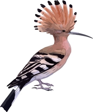
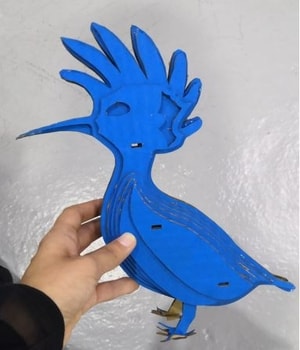
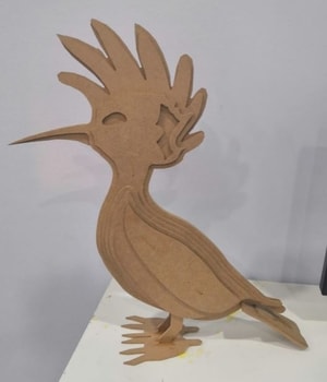
For this week we were asked to design birds for an exhibition in Bahrain. Those birds planned to be produced using CNC machine. All birds should be designed and sketched as 2D first. Then, we cut the pieces using CNC and assemble the parts to get the 3D model of them. Hence, I have started by looking at the different types of birds in Bahrain listed in this blog. After I looked at them all, I decided to design a bird called Hoopoe. Here are some picture of it:

First, to design the bird as 2D, I have used Inkscape. All the parts of the bird had designed in this software following those steps:
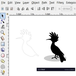
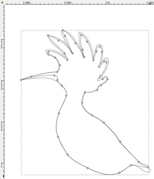
1- I have started by searching for a silhouette image. I found many but I have chose the following.

2- Then, I import the image in Inkscape by clicking on File > import.
.jpg)
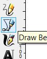
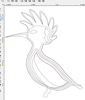
3- Then, I have traced the body of the bird by clicking on the tracing tool from the toolbar on the left side.
4- After the tracing completed, I dragged the image out to see how good my tracing is.
5- Then, I deleted the image and kept the body outline. This was my first piece (part) in the design.
6- Next, I created a copy of the outline and edit it by clicking on the path > object to path.
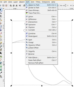
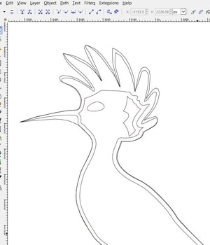
7- Then I was able to see the nodes, so I started editing them to show some details of the bird like it beak, head and tail. That was layer 2 of my design.
8- Next, by using the “linked offset” tool, I have created layer no.3 to show more details of the bird like it eye.
9- Then, another offset.
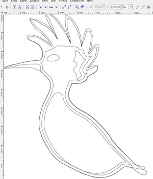
10- Then, with layer 5 I have created the legs.
11- I kept adding layers until I end up with this design.
12- Then, I traced the foot and tail of the bird.
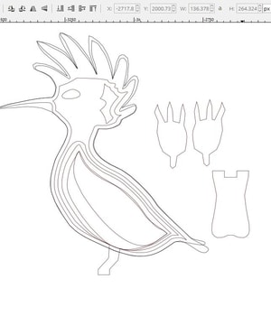
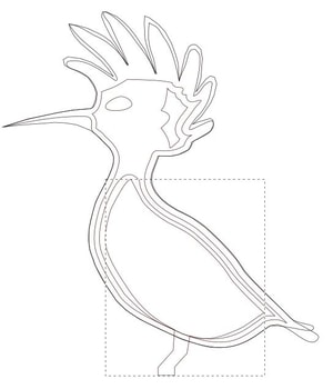
13- For the joints I have drawn rectangles that their height/width same to the material thickness.
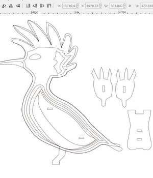
14- To ensure that all the rectangles (joints) are located on the same place, I have duplicate them. Then, combine each layer with the joint until I end up with this.
Note that for each layer I made 2 copies, so I can have the 3D model of the bird.
Testing with laser machine
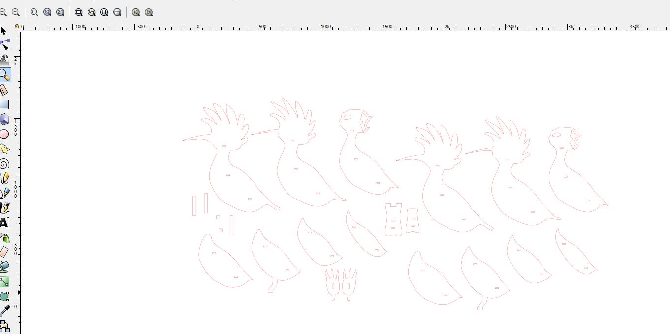
I have tested the design with laser machine before cutting the parts directly with CNC. The purpose of this test was to see if there is any errors in the design, so I can fix them before cutting the big model with CNC. Steps of cutting with laser had explained already in week 4. Here is the result:
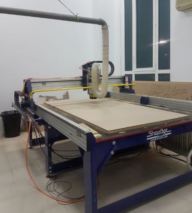
CNC machine
Machine setup and cutting process are explained below.
1- We start by placing the sacrifising board.
2- Then, we placed a High Density Fibreboard (HDF) on the sacrifising board. The board thickness of the board that I have used is 6mm.
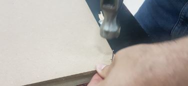
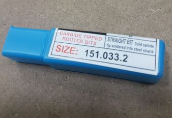
3- We placed the following drill bit in the machine.
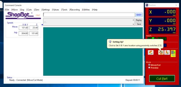
4- After that, we set the origins of the machine (X, Y and Z) by using the machine software.
The following figure shows the setting of X and Y origins
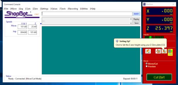
The following figure shows the setting of the Z origin
5- I made sure that the dimensions of my file are connect.
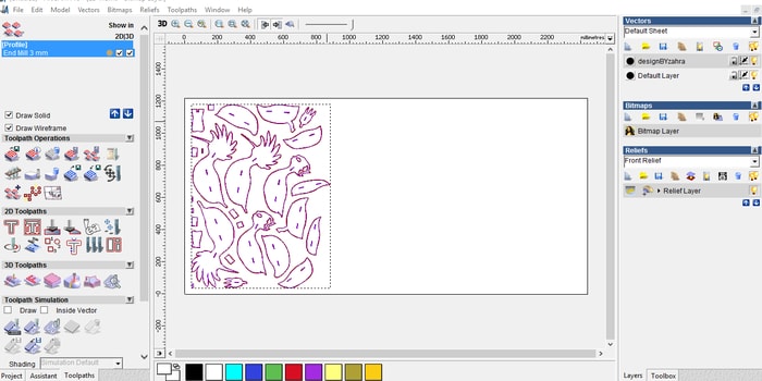
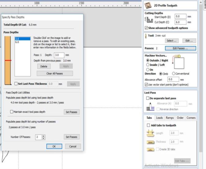
6- By using the VCarve Pro software, I entered the settings. This includes the dimensions of the board and the start position.
2D Profile Toolpath 6mm cutting depth One pass 3mm, 2 passes in total Machine Vectors (Outside/Right):
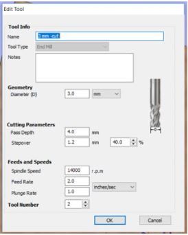
7- The following tool setting has been entered.
And here is a video while the CNC was cutting my pieces
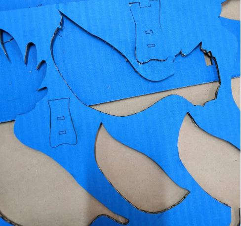
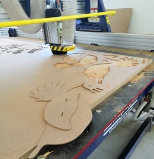
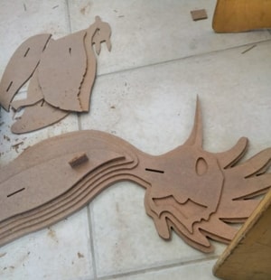
8- Final result is showing below:
It is worth to say that the speed and the feed rate of the machine was chosen based on the datasheet that comes with the ShopBot machine. To view the datasheet, please see the link.
To download the design file, please click on the link here.