Group assignment

review the safety data sheets for each of your molding and casting materials, then make and compare test casts with each of them

The group Assignment link can be found here: Week 10 Group Assignment

Individual Assignment

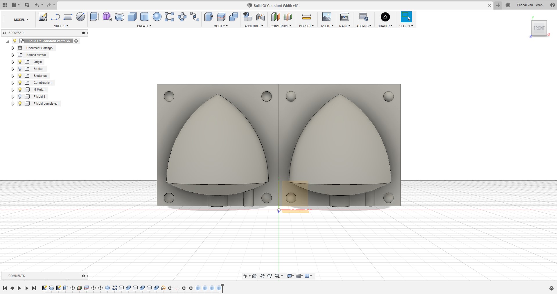
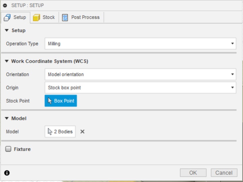
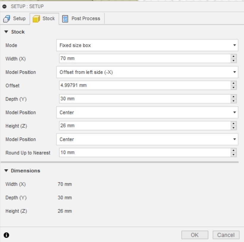
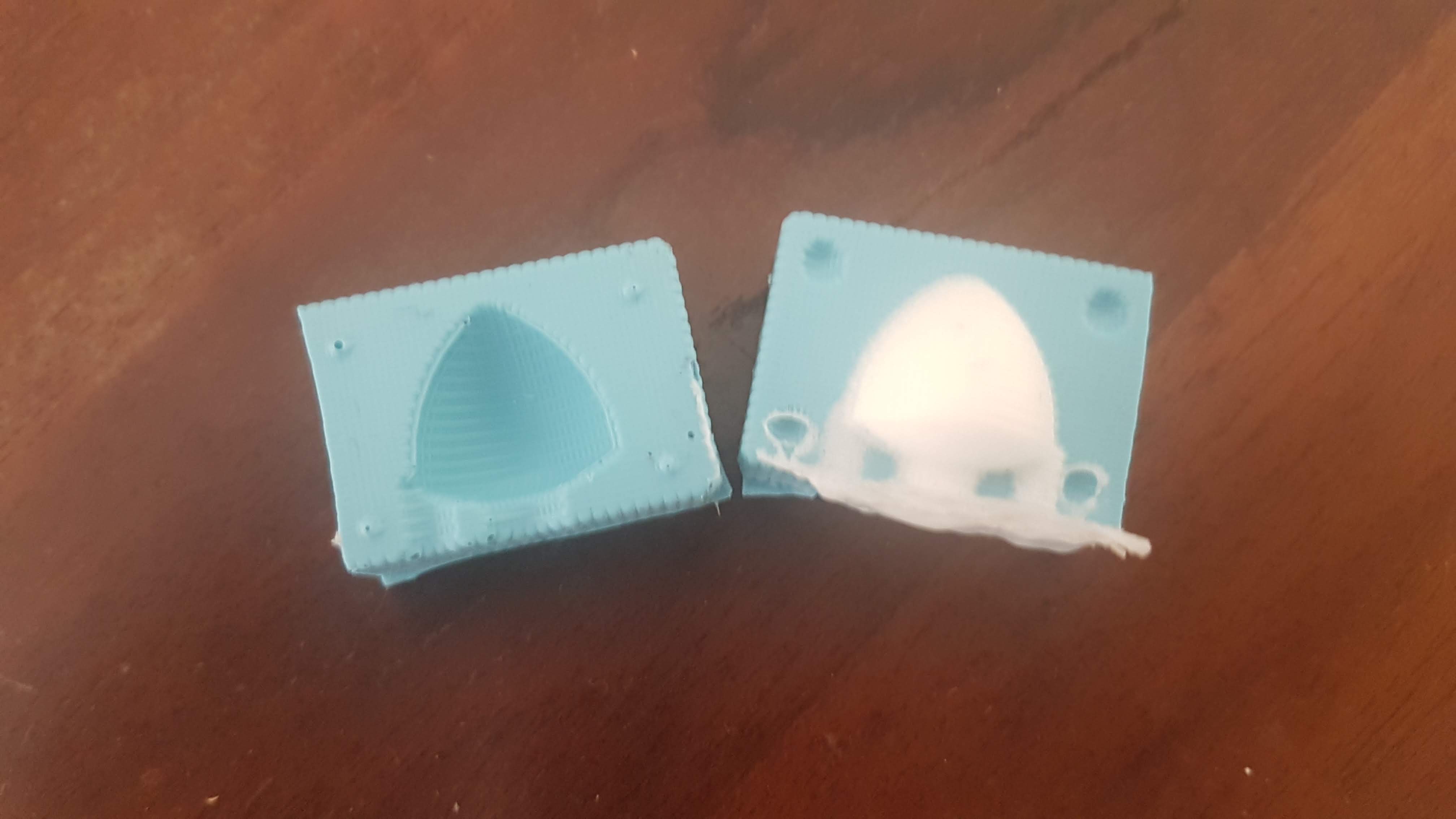
Design a 3D mold around the stock and tooling that you'll be using, machine it, and use it to cast parts.


Designing the Mold

Once again I chose Fusion 360 for this assignment. And was ready to try my hand at the Reuleaux Tetrahedron.

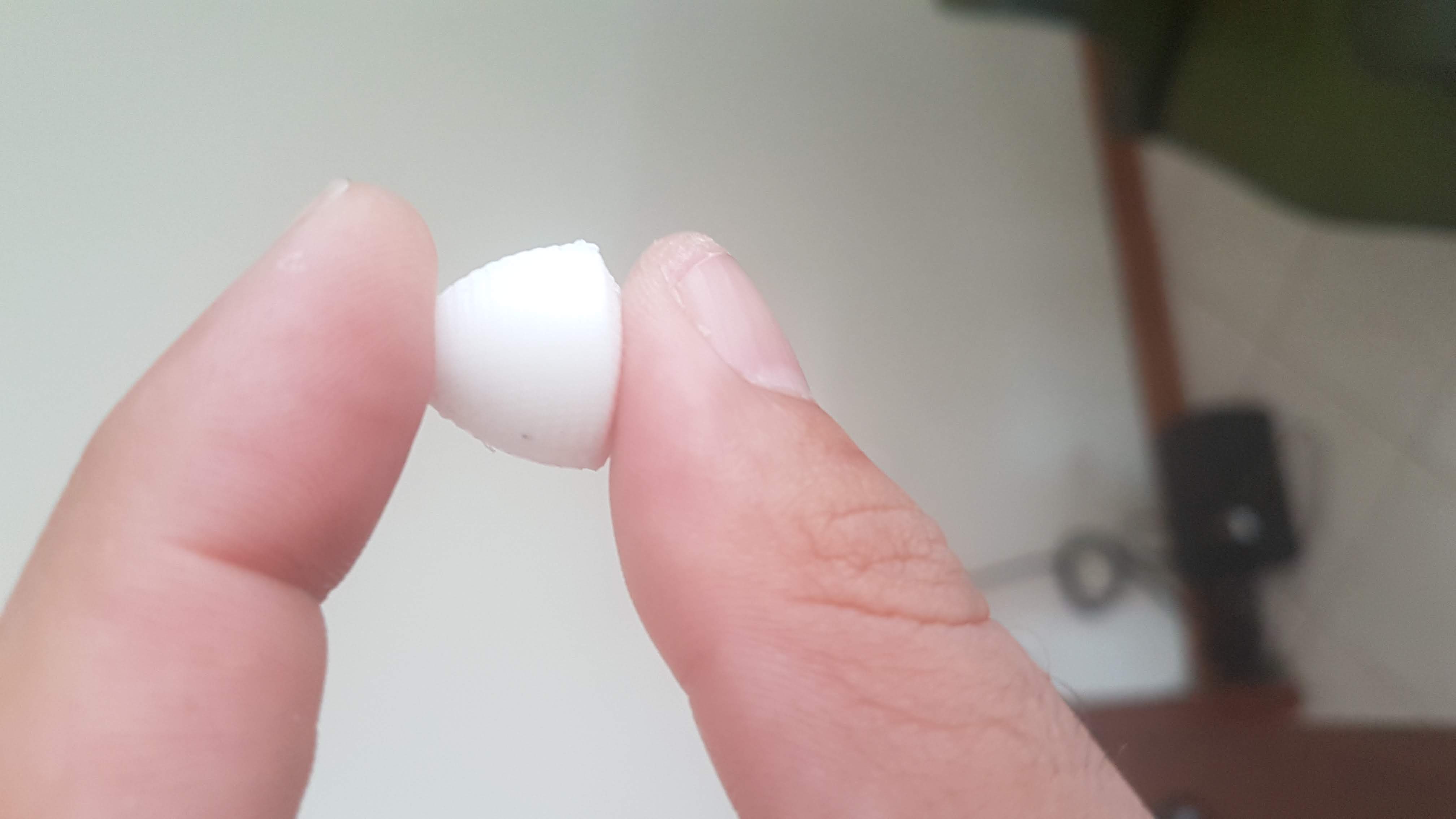
From this R.Tetra, I want to try and make it a Solid Of Constant Width.

So let's fire up Fusion and get to work!


Trying to grasp the math of the R.Tetrahedron.
Choosing VSCode as Git's default Editor

Oooh boy...

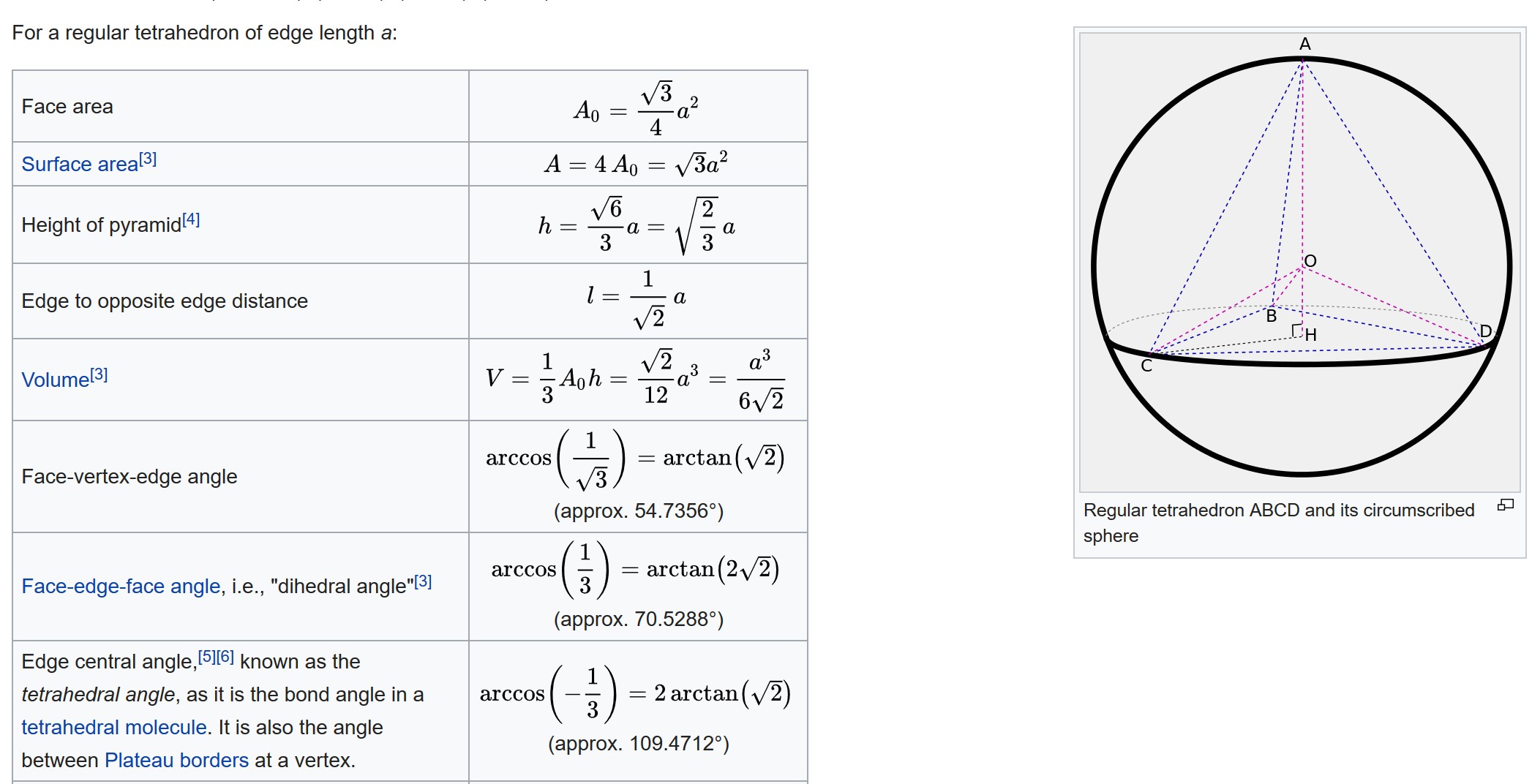
The Reuleaux Tatrehedron in a three dimnsional state, is akin to a pyramid with 3 sides of equal length. It is then rounded off by a circumscribed sphere.

Meaning, it will have to pass through all the vertices or points of the triangle.

My first attempt will be to draw a triangle of equal sides and then to find the center, in order to find the 0 point in the axes of Fusion 360.

Choosing VSCode as Git's default Editor

Find the Center of the Triangle

Choosing VSCode as Git's default Editor

Center the trianlge and then move it downward.

Choosing VSCode as Git's default Editor

Centered.


Now we need to extrude the triangle and create a tetrahedron/pyramid from it. We use the square root of 2/3.a . And this can be typed into Fusion.

My sides are equal sides of 50mm meaning the formula is going to be : 50*sqrt(2/3). Now that we have our height, we need to bring the edges together.

This can be done with the Draft function in Fusion 360. It rotates the faces around the axes.

We select Draft, and then select the bottom face, and then the left and right side faces. We leave the top face alone, as we want to rotate the other faces in order to make our pyramid.

Editor's note: as you can see, I lost all my pictures in the making of this process.

Now we look at the Face-Edge-Face Angle in the wiki page for the formula. Arcus(inverted) Cosinus(1/3)=arctan(2.sqrt2)

Alright, let's do it....or rather not. In Fusion the formula was making the edges go outward instead of inward as expected. So in order to bring them closer I tried with negative 90 (trail and error(s) got me to -90).

I was struggeling quite a bit, but the formula that finally made it to a pyramid was: -90+ atan(2*sqrt(2))

I have my pyramid. Now this is where things started to go wrong for me. Most likely a math problem. But whenever I tried to draw the arcs, I noticed that the pyramid was not adhering to the center of the triangle. Meaning the arcs would not be of equal lengts.


The K.I.S.S. for Troubleshooting.

After going back to back, with the redrawing and trying to understand where I went wrong with the formulas, I finally said OK!, back to basics.

Choosing VSCode as Git's default Editor

The Visual Cue, which reminded me.

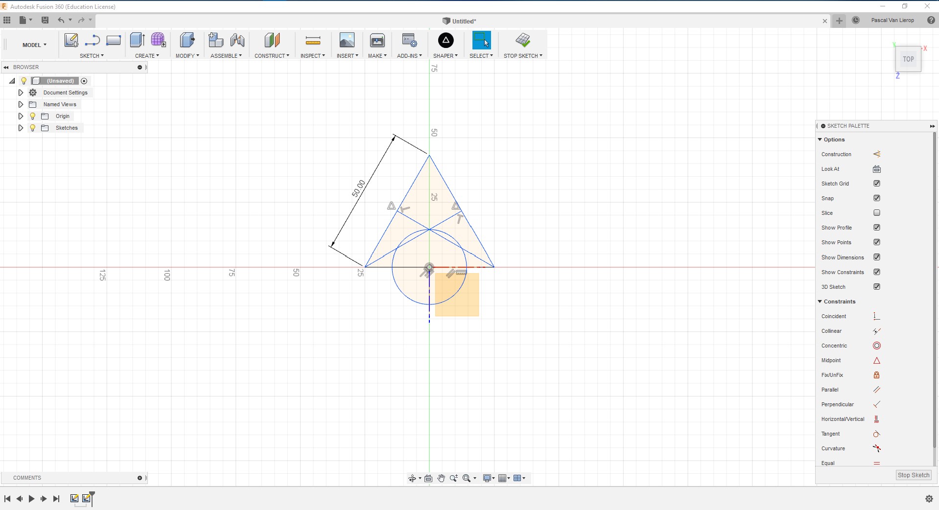
I'll take this chance, so call me blind... SO I went to zero and started with a simple skecth of a triangle.

Choosing VSCode as Git's default Editor

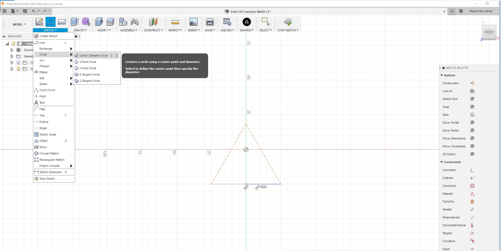
Draw a trianlge with equal sides.

Choosing VSCode as Git's default Editor

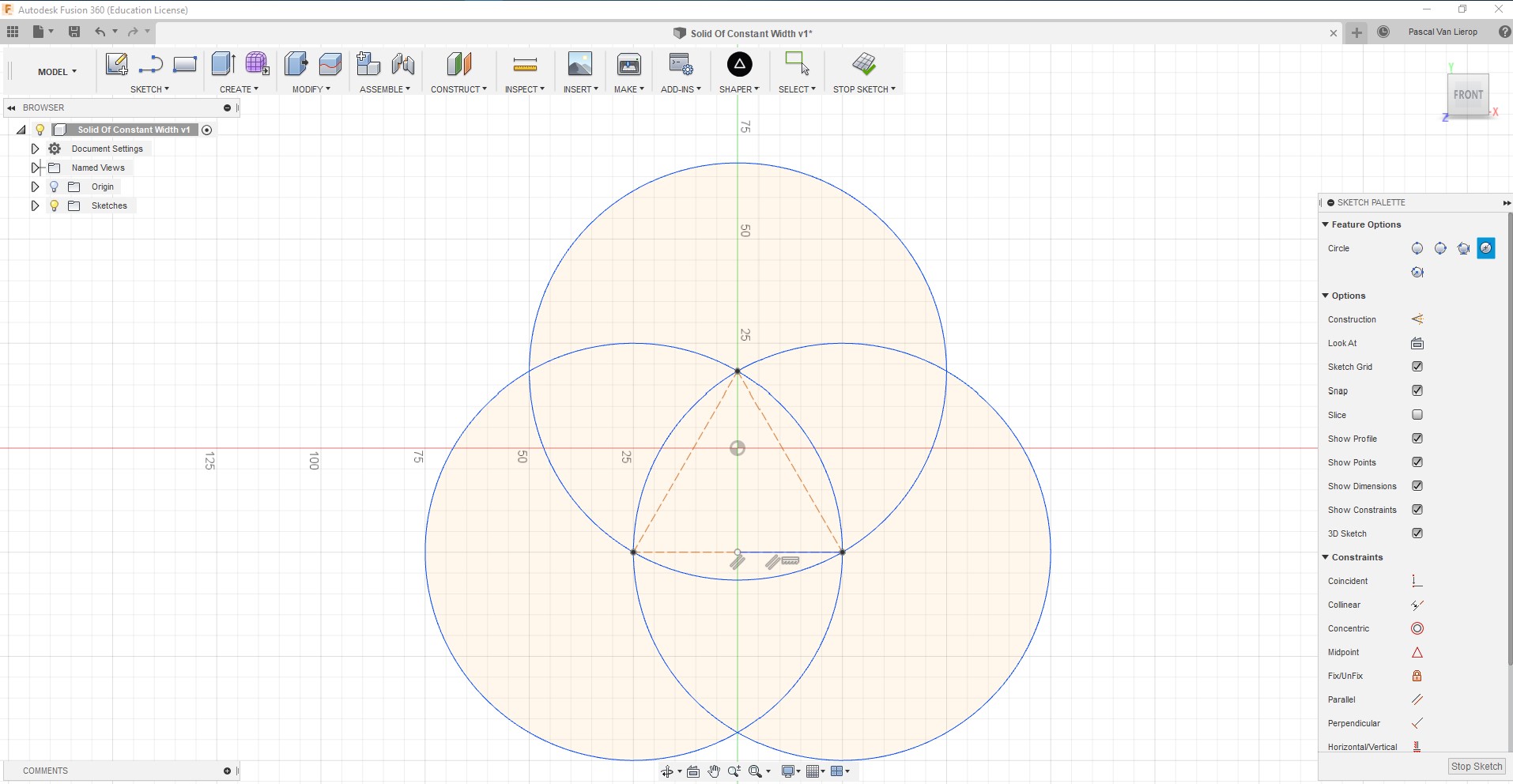
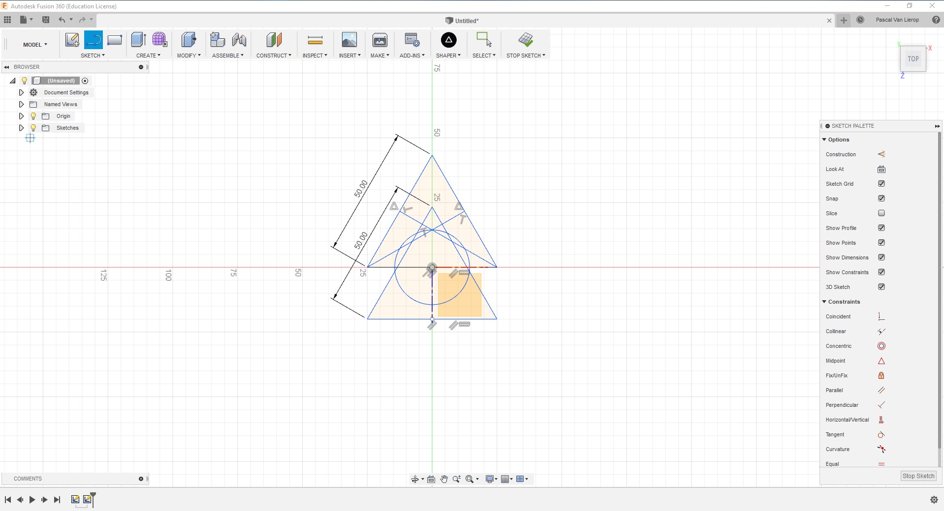
Draw circles starting from each point of the traingle

Choosing VSCode as Git's default Editor

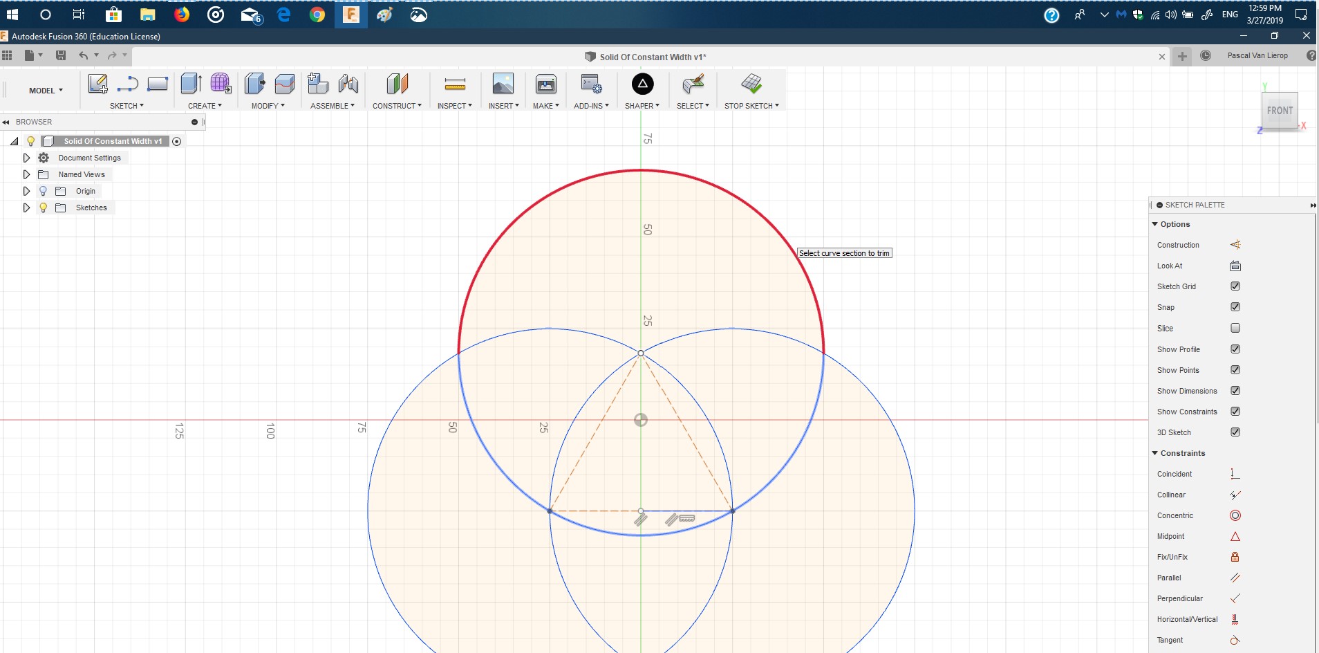
Trim the outer arcs.

Choosing VSCode as Git's default Editor

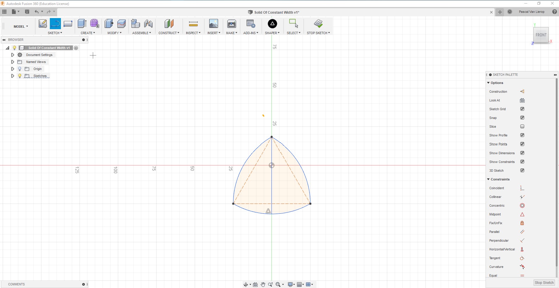
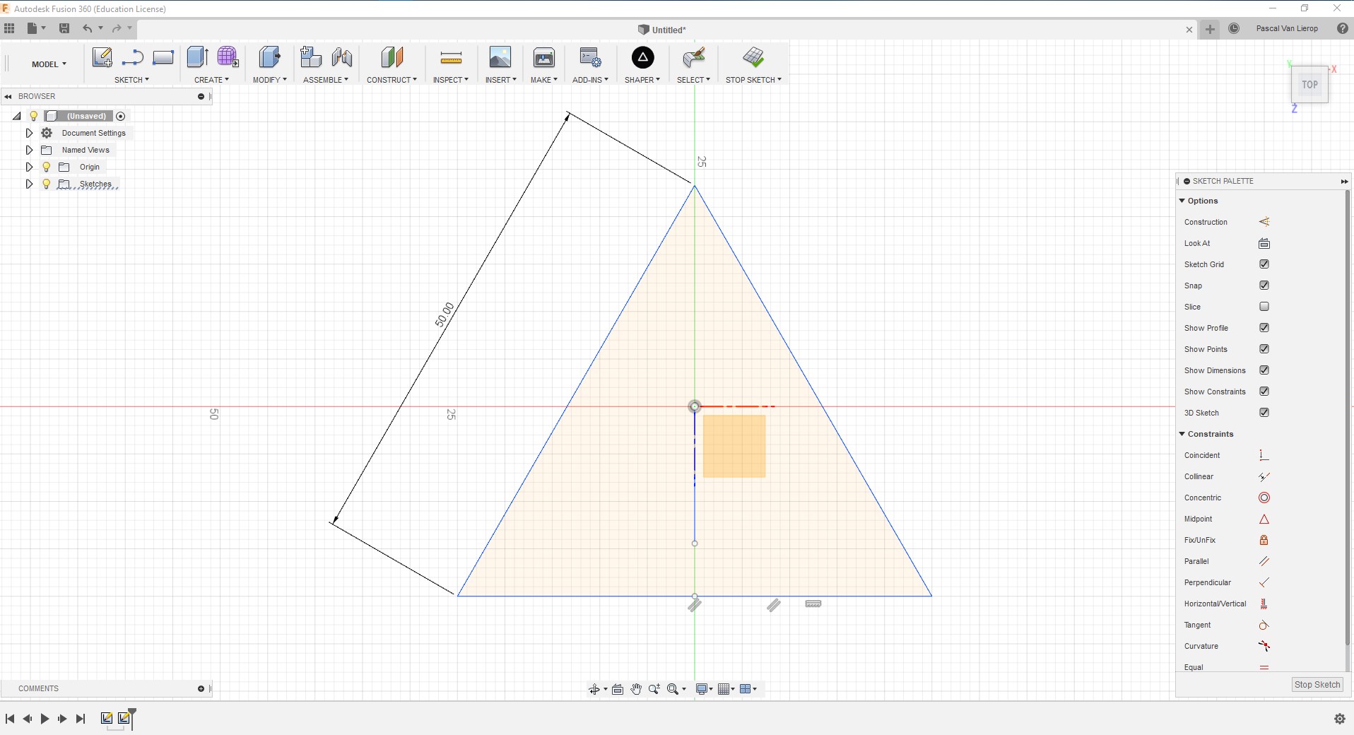
Now we have arcs of equal lengths.

Choosing VSCode as Git's default Editor

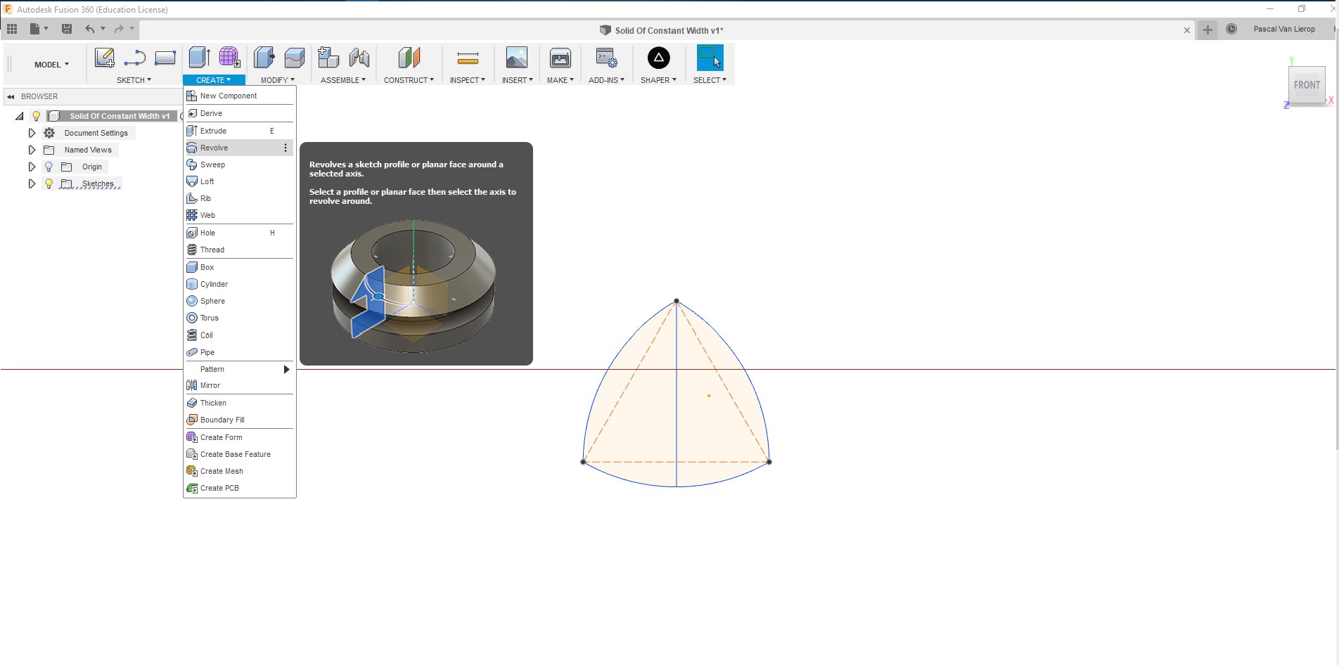
Now we revolve our Triangle

Choosing VSCode as Git's default Editor

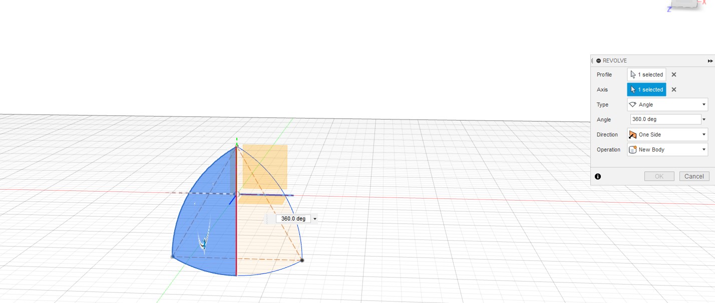
We Select the face we want to revolve and then the plane. Just select the opposite plane/direction.

Choosing VSCode as Git's default Editor

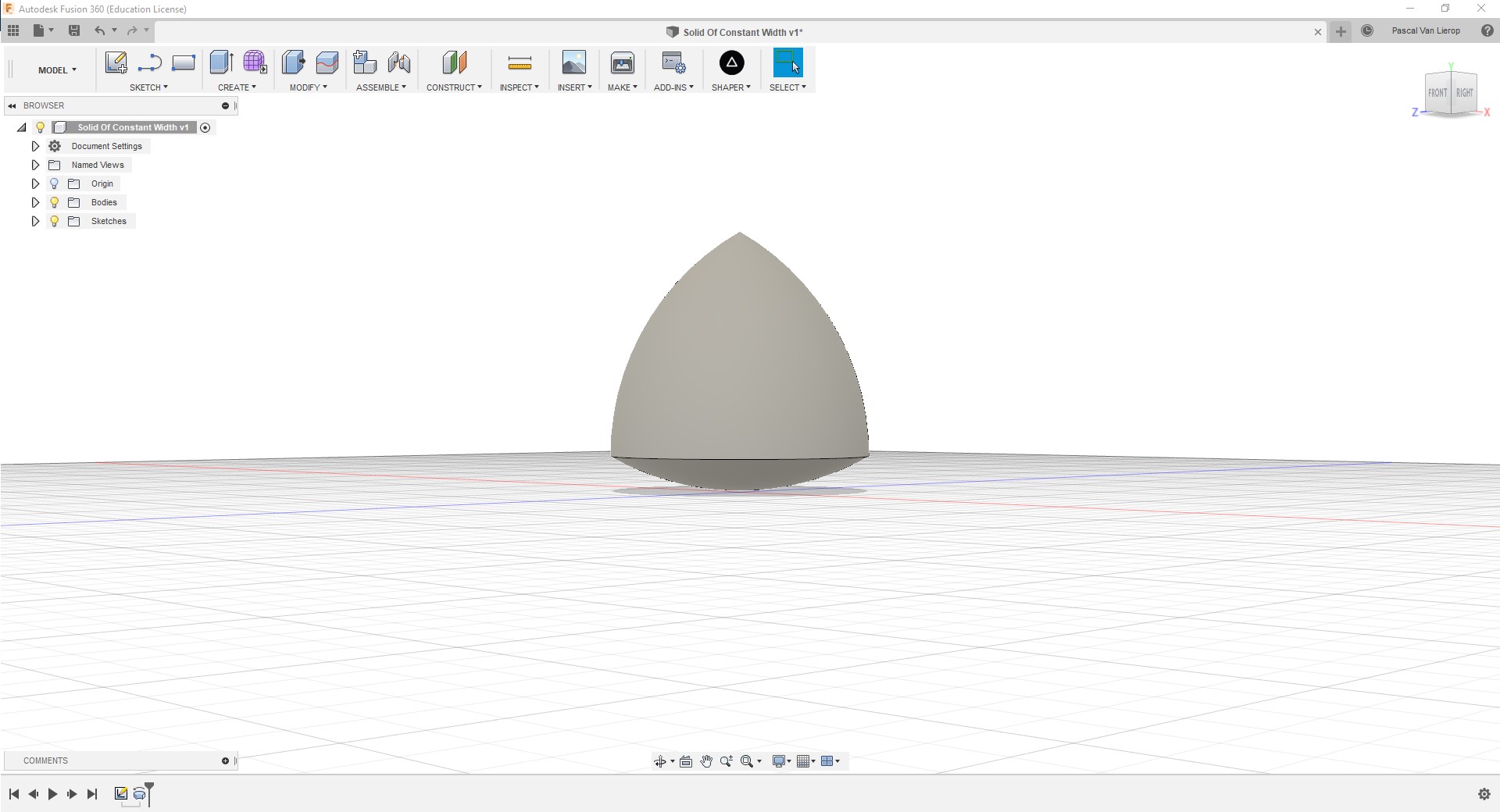
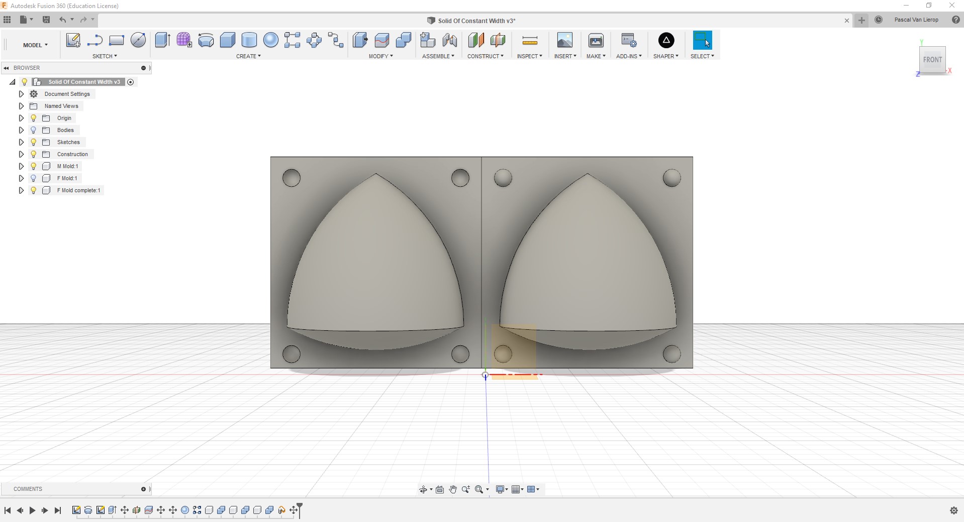
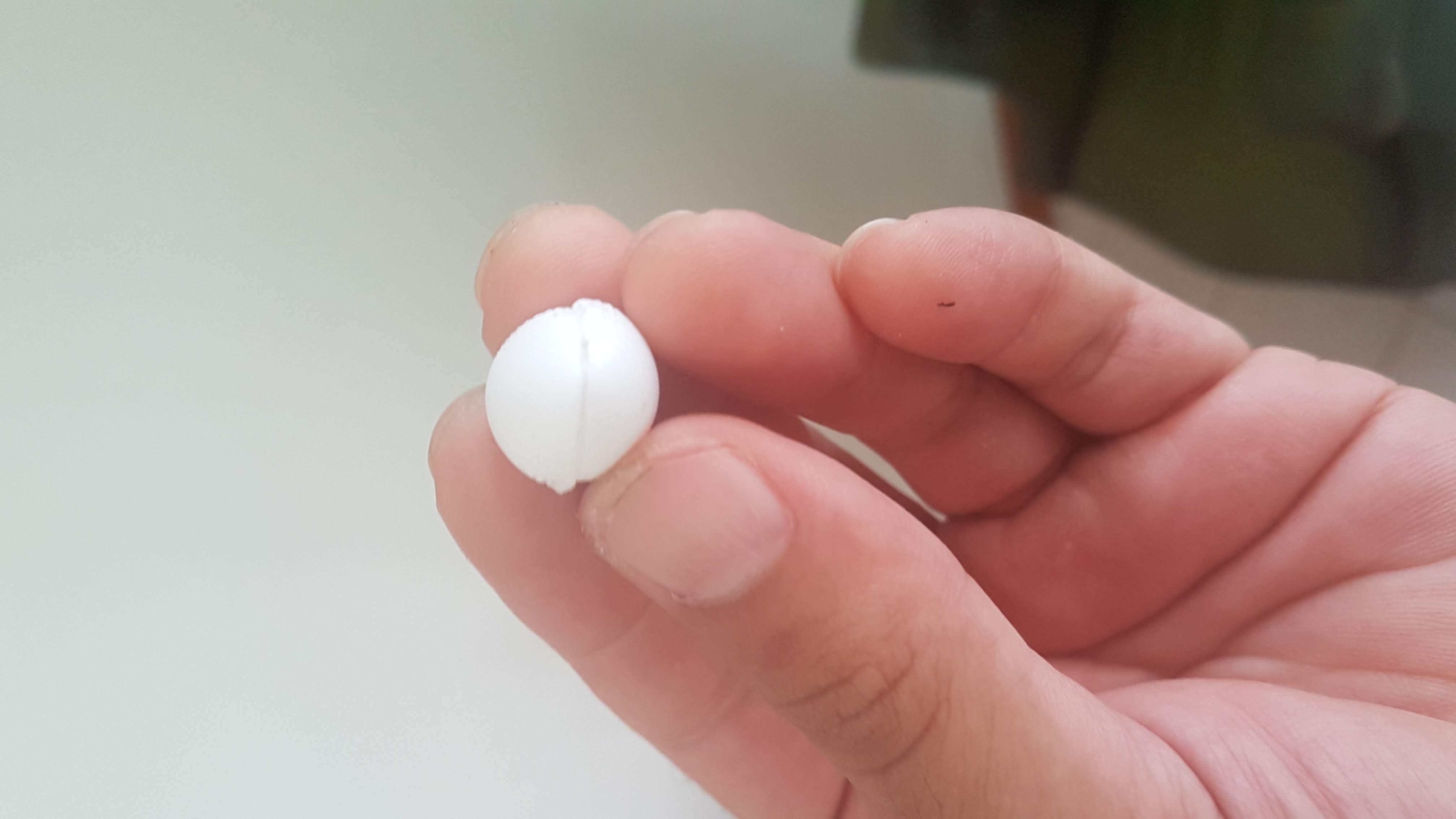
Make it revolve 360 degrees and voila! we have our Solid of Constant Width.


Making the mold

In order to make the mold, we fisrt need to draw a rectangle at the bottom face on the center of the SoCW (Solid of Constant Width). Extrude it and then create a new body.

To make things easier, we can always change the opacity of the rectangles body in order to see the SoCW.

We need to divide the rectangle (please click on the lamp icon next to your socw, in order to disable it) and select Construct->Midplane.

Choosing VSCode as Git's default Editor

We are going to split the square.


Now that we have two halves, it is best to place the spheres, we will be using as pegs.

Choosing VSCode as Git's default Editor

I used a sphere of 5mm in radius.

Choosing VSCode as Git's default Editor

Create a rectangular pattern selecting the sphere feature in the design timeline.

Choosing VSCode as Git's default Editor

The rectangular pattern makes shure the pegs, are equally distnaced from one another.


Now we need the negative of the pegs in the other half of our square and in order to do this, we combine the two halves, effectivaly subtracting the sphere on the other half of the square.

Choosing VSCode as Git's default Editor

Make sure the socw is turned off, when combining.

Choosing VSCode as Git's default Editor

We successfully subtracted the spheres from the other half.

Now we turn one half of the square off and turn on the socw.

Choosing VSCode as Git's default Editor

We combine the left mold with the socw.

Choosing VSCode as Git's default Editor

We do the same with the right half.

Choosing VSCode as Git's default Editor

Move the combined pieces and lay them out for CNCing.


We can now place the fill and air holes. I did this using the Create->Cylinder and added them to both bodies.

Choosing VSCode as Git's default Editor

Finished mold.

You can download the STL file here:Download

CAM process.

I will be using a lot of the same strategies for the CAM process as I did in week 8. Instead of a 2D cut however I will be using 3D pocket clearing and Parallel cutting.

The setup will be practically the same as week 8's assignment, the only difference is the 0 point. This time around I selected the Box Point as my 0 point

And used the models for my orientation.

Choosing VSCode as Git's default Editor

Main setup.


I then proceed to creat the stock it's real life dimensions, which are:

  • Width = 70mm
  • Height = 26mm
  • Depth = 30 mm

Choosing VSCode as Git's default Editor

Stock Settings.


3D Pocket Clearing.

I left the post processing tab, alone for now. I can do that in a more advanced post processing window later on.

No I want to create a setup for 3D Pocket Clearing, which can be found under the 3D tool on the toolbar.

The setup for the "1/8" (3.175mm) Flat Endmill is as following:

  • Spinde Speed = 1600 rpm
  • Feedrate = 1000 mm/min
  • Lead-Out & Ramp Feedrate = 20 mm/min

Choosing VSCode as Git's default Editor

Tool settings.


Here I was having some issues, with the simulation, as it was cutting away at my pegs. So I came to the conclusion that my Geometry was off.

I had a better simulation once i Selecte the Machining Boundry to be bound to the box and the Tool Containment to stay inside the boundaries of the cutting area.

Choosing VSCode as Git's default Editor

The working Geometry settings.

Choosing VSCode as Git's default Editor

The heights seemed OK, especially once the simulation ran, without any errors.

Choosing VSCode as Git's default Editor

I am going to run just one pass, so this I left at default.

Choosing VSCode as Git's default Editor

I also left the linking on default, as it is calculated beforehand, depending on your tool settings and geo.


Parallel Cut

For the parrallel cut, I used the same tool parameters, but only for a Ball Endmill, with a cutting diameter of 3.175 mm.

Choosing VSCode as Git's default Editor

Tool settings for the Parallel cut.


For the geo. parameters, I selected Silhoute of the main setup. This will ensure for a clean-up of the rough cut.

Choosing VSCode as Git's default Editor

Finished mold.

Choosing VSCode as Git's default Editor

Again, the heights seemed fine, so left at default.


During simulation, of the parallel cut, I was not satisfied with the cleanliness of the mold. So I went back lowered the stepover to 0.5875 mm (I just subtracted 1 mm) and added a Perpendicular pass.

The simulation resulted in a cleaner cut, due to the smaller stepover.

Choosing VSCode as Git's default Editor

Added Perpendicular pass and smaller stepover.

Choosing VSCode as Git's default Editor

I left the linking on default settings.


Creating the .NC files.

Because we created to seperete jobs, we need to create individual .nc jobs for the milling. In Fusion 360 this is called Post Processing and can be found either in the toolbar, or by right clicking your setup.

The first mill job was cutting horribly. The plunge was waaay to slow (took about 1 min helixing around before cutting) and the Z axis looked inverted.

The issue with the .nc file was that it indeed started with a -Z, which was making the Stepcraft 840 confused(? no just cutting with the wrong params.)

In order to fix this, you will require the correct post processing library, for the correct software. I for example am using Stpecraft's UCCNC

I looked up the post library for UCCNC and if you are using any different kind of CNC machine, that does not show up in the Fusion post library, you can try your luck here AutoDesk HRM Post Libraries

Once dowloaded, you will need to place the .cps file in the post library folder. This can be opened at the Post Processing window here:

Choosing VSCode as Git's default Editor

Open The Post Configuration Folder.


Choosing VSCode as Git's default Editor

Be sure to add them to the post library folder.


We now save the jobs into seperate .nc files.

Choosing VSCode as Git's default Editor

After selecting the correct posts configuration, you can name adn comment your post before creating your .nc file

Note*: If you do not see the added library, close the window and re-open it.

Choosing VSCode as Git's default Editor

Now we do the same for the parrallel cut.

You can download the .NC for Pocket Cut here:Download

You can download the .NC for Parallel Cut here:Download

Milling the Mold

Now it is time to mill the mold. I am using the Stepcraft D840 with the MM-1000 spindle

The software is UCCNC by Stepcraft. With this piece of software I can position the 0 point and start the milling job.

Once the .nc file is uploaded, you can click on the tartget icons to set your axes, and jog it manually to see if your mill goes out of bounds of your stock or not.

If it does, you can always stack on your previous 0 position to calibrate the mill to your design. Once correctly calibrated you can press Cycle Start to run the job.

Choosing VSCode as Git's default Editor

The Pocket Clearing job.


My mistake was not to have the right feed rate for the helix operation, taking more than 1 min to lower the bit for the cut. Once the mill has reached the right depth, however it cuts it fairly fast.

The proccess for the parallel cut is the same.

And this is the result:

Choosing VSCode as Git's default Editor

The negative mold complete.

Nice and clean, although I did leave the Plunge Feedrate at auto calculation, which made the helix operation unbearably slow.

Next time , I will alter for a quicker job.

Casting

After the milling job

Choosing VSCode as Git's default Editor

Time to mix the Omoo Silicone. The ratio is 50/50

Choosing VSCode as Git's default Editor

Looks a bit much, but I have a heavy hand/foot.

Choosing VSCode as Git's default Editor

After a few day, it looks quite promising.

Choosing VSCode as Git's default Editor

Should have mirrored the design, as it is not alligned properly

Choosing VSCode as Git's default Editor

Not really McGuyver standards, but it will do.

Choosing VSCode as Git's default Editor

The Omoo plastic A & B. The ratio is 50/50

Choosing VSCode as Git's default Editor

Pouring in the plastic.

Choosing VSCode as Git's default Editor

Time to open her up

Choosing VSCode as Git's default Editor

Seemed promising.

Choosing VSCode as Git's default Editor

Not a Solid of Constant Width at all, but lessons learned.

Choosing VSCode as Git's default Editor

Not alligned properly

Choosing VSCode as Git's default Editor

Still kinda cute, though. Eh?

What did I learn?

To be honest I could have made the Solid of Constant Width a lot better, if had only mirrored my design, but it is a learning process and will have to get better the next time around

All in all, I did learn a lot about the modeling and CAM process, yet again in Fusion and will take these aquired skills over into designing my final project.

And to be fair the socw, does roll quite nicely, without too much of a bump, so I was close. Next time bigger and better!