Individual Assignment
Measure something. add a sensor to a microcontroller board that you have designed and read it.
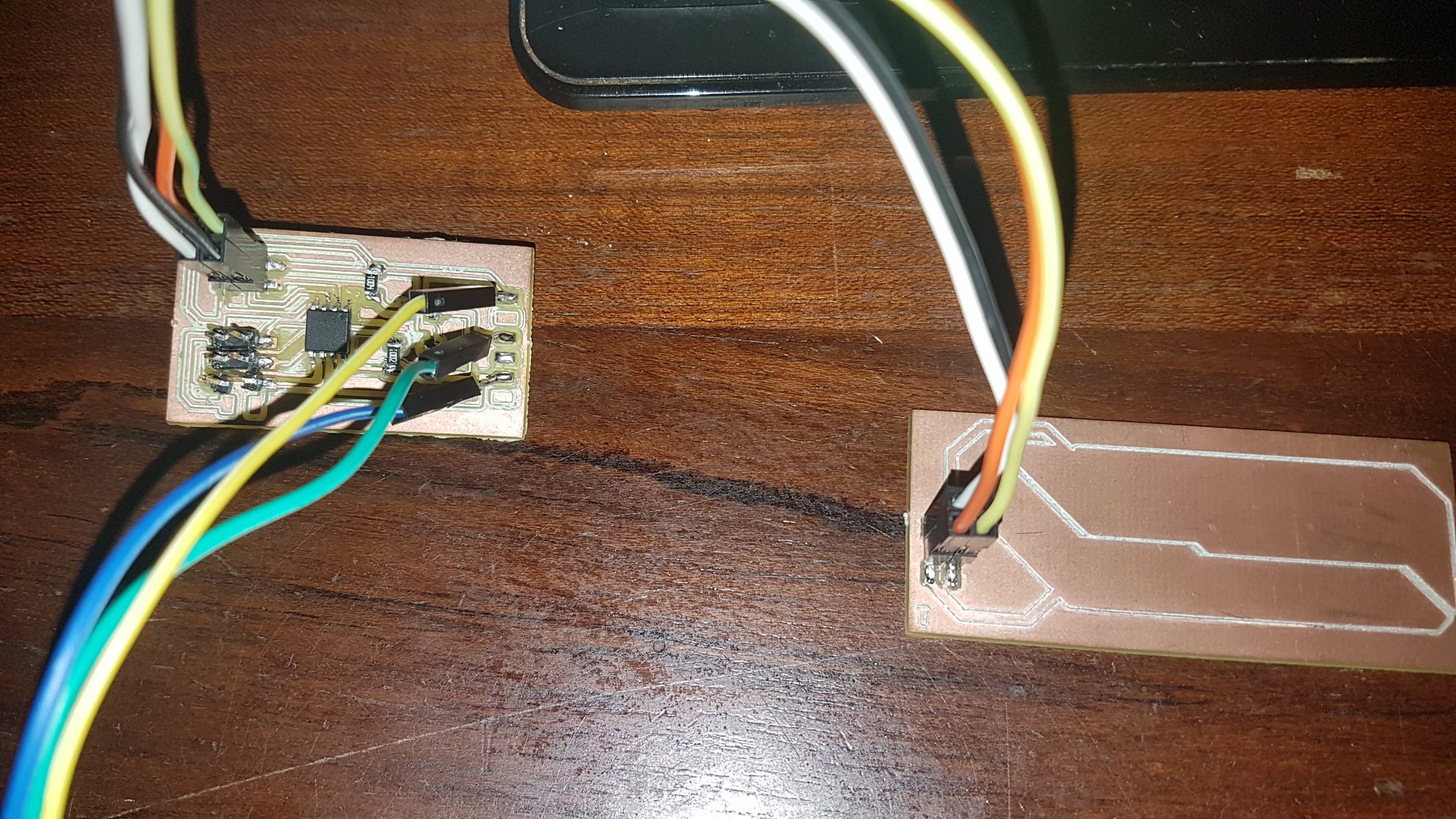
Making the Hello.txrx board.
For my project, I might try a strumpad to at least emulate the playing of strings and or palm muting the strings
The step response board, might help me in learning the process of it all.
I took to redrawing Neil's txrx board with the ATTiny 45.
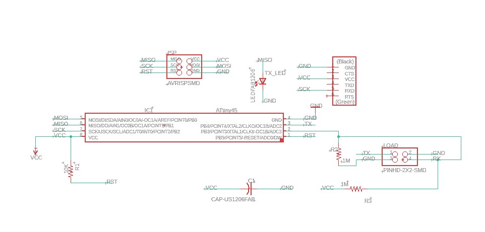
The Schematics of the Hello board.
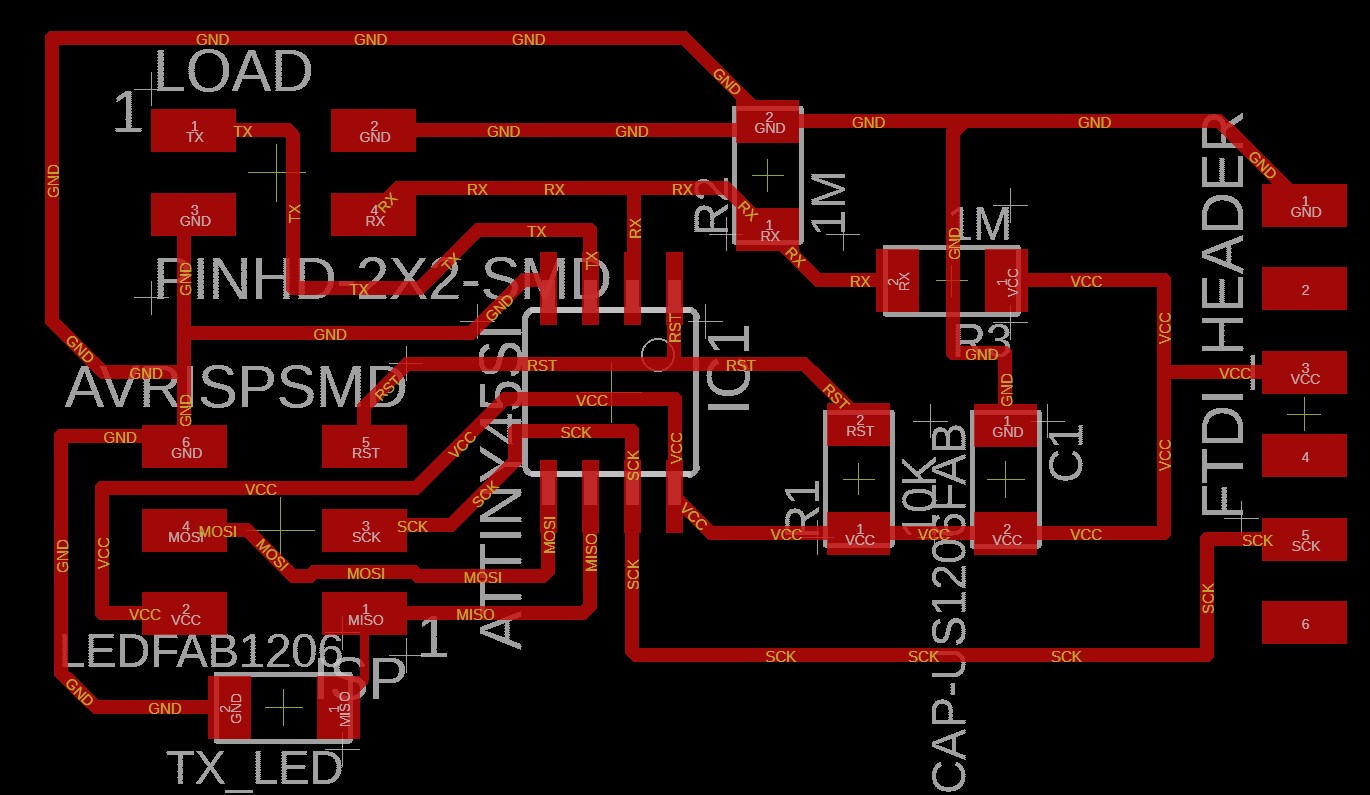
The PCB layout of the Hello board.
After I redrew Niel's hello board I made the pad in eagle as well, using the polygon feature. Still quite new to this workflow, but still came out rather well
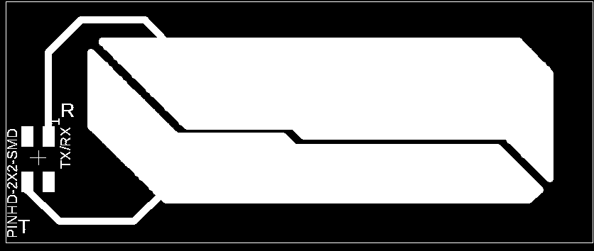
The TxRx pad.
I used Flatcam to create the gcode for the mill with the following settings:
- Cut Z: -0.15mm
- Travel Z: 1.2mm
- Feedrate: 60mm/min
- Tool Diameter: 0.4mm
- Spindle Speed: 7000 RPM
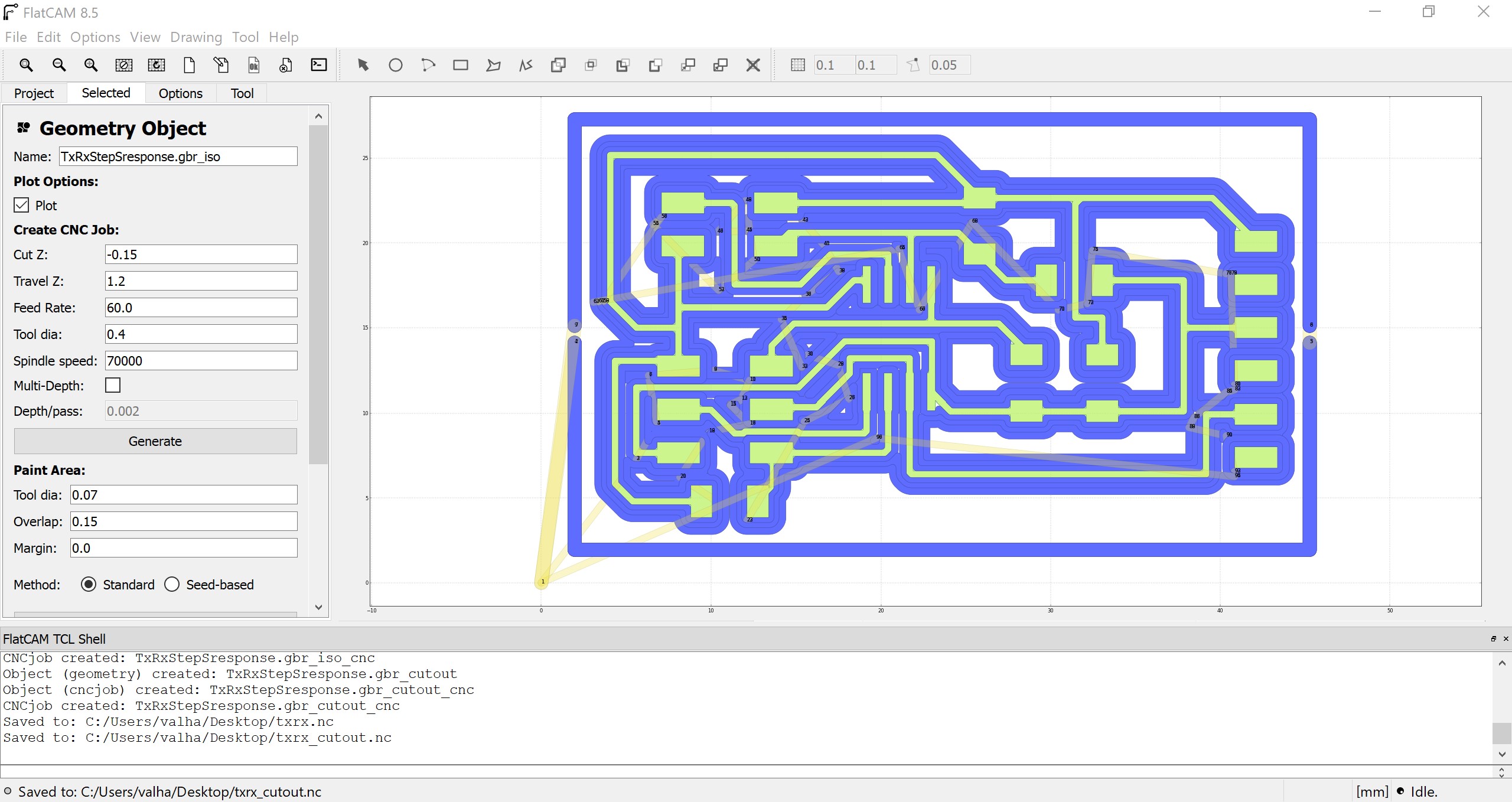
Generating the trace of the Hello board.
For the cutout I used the following settings:
- Cut Z: -1.6mm
- Travel Z: 1.5mm
- Feedrate: 30mm/min
- Tool Diameter: 0.8mm
- Spindle Speed: 7000 RPM
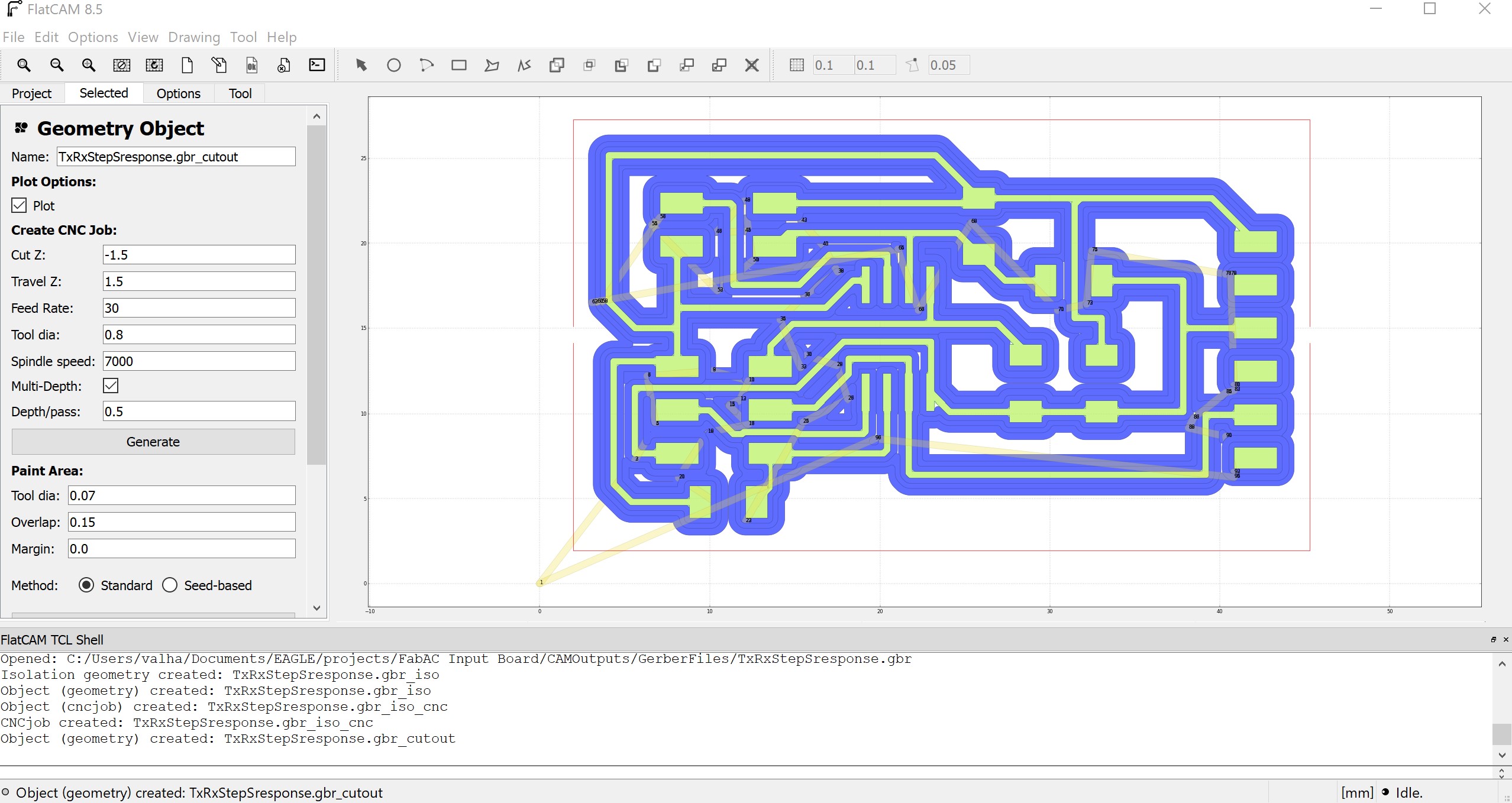
Generating the cutout of the Hello board.
For the TxRx pad, I used the same settings.
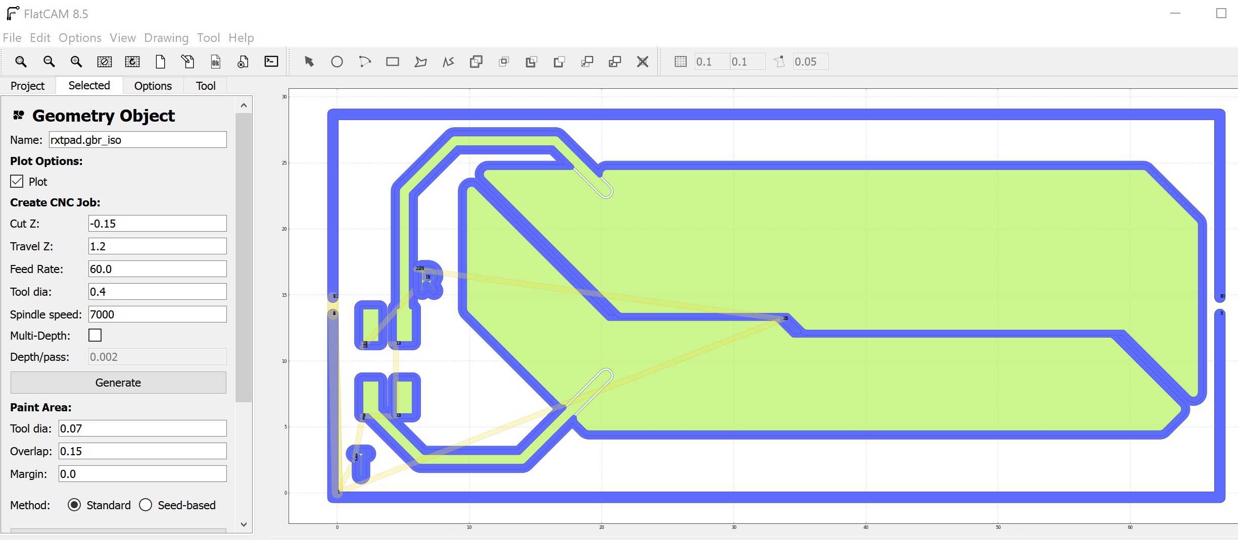
Generating the traces of the TxRx pad.
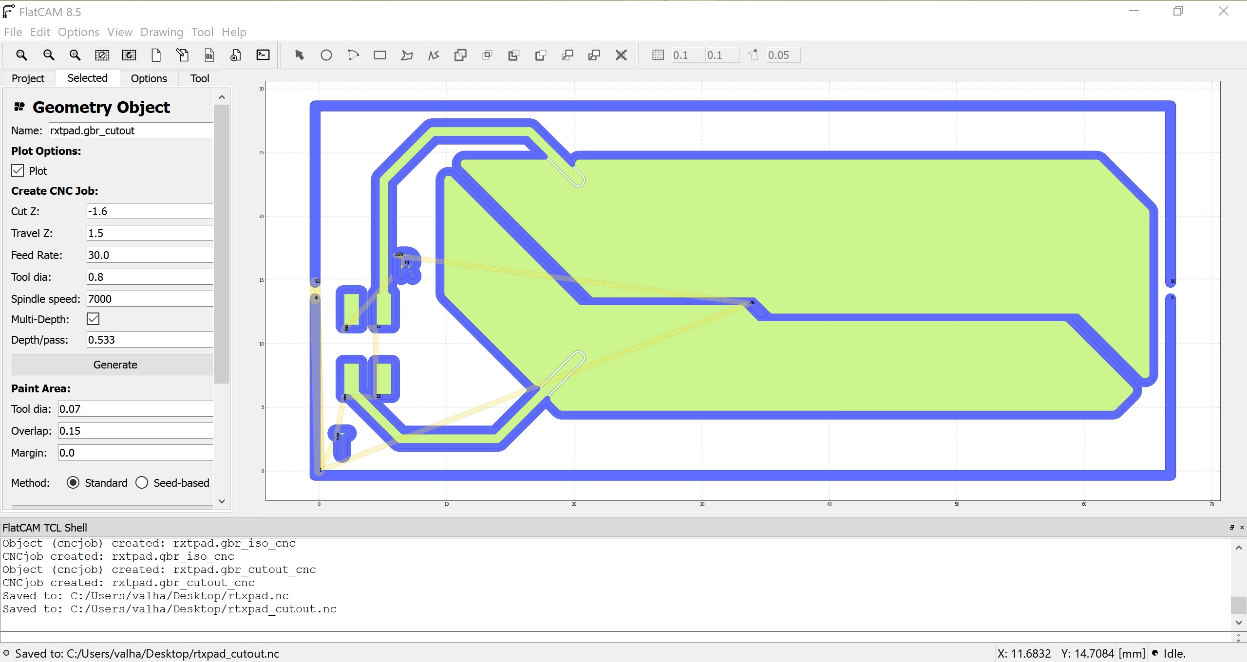
Generating the cutout of the TxRx pad.
Milling the Board
For this process, I used candleCAM, which uses GRBL to communicate to the mill.
Candle is quite neat, as you can use the software to create a heightmap of the cu plate.
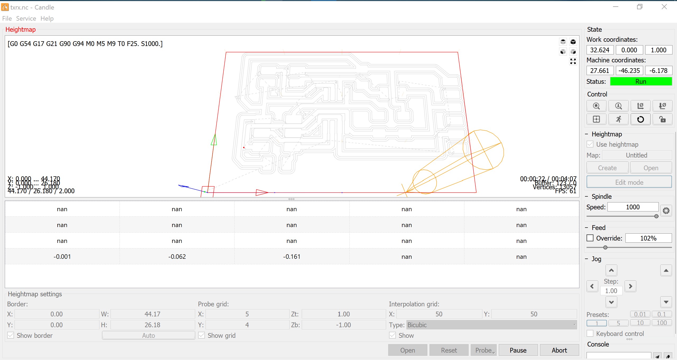
Generating the heightmap.
The heightmap can be used for all jobs, if you want, but I am using it just for this cu plate.
The same process for the pad.
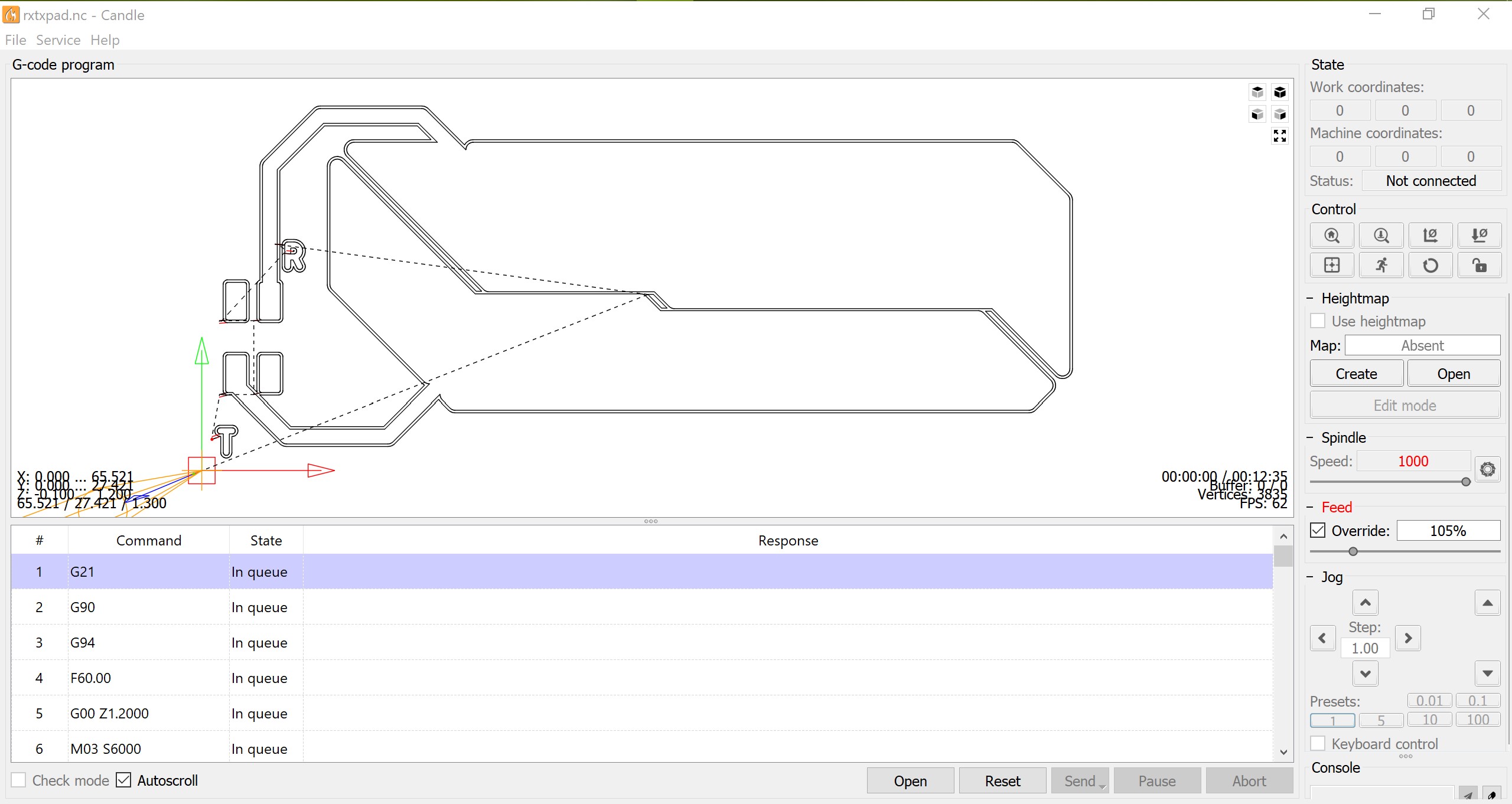
Milling the TxRx pad using Candle software.
Milling the TxRx pad using Candle software.