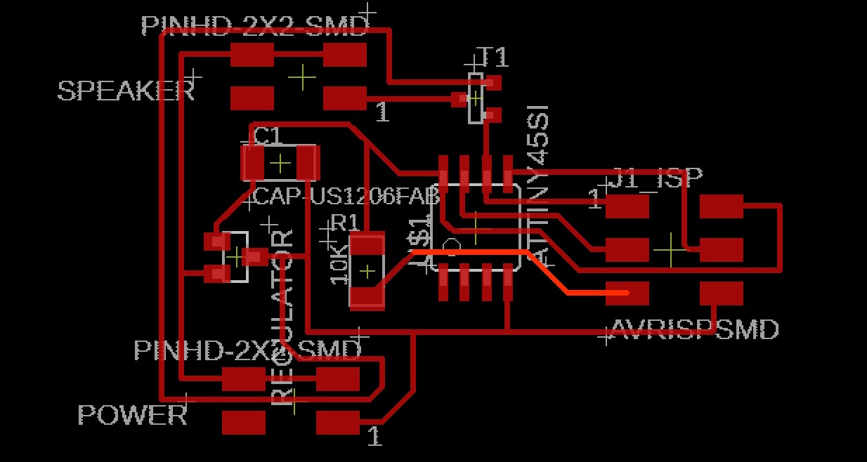
I actually milled the output board the same day as the input board, so I used the same heightmap, that I created before the milling job.
Programming the board.
After the milling job and stuffing of the board, I only ran intpo one issue. The IC regulator got super hot, the instant I powered the board.
I thought I had made a mistake during the stuffing (the MOSFET SMD package is almost identical) but I was told by my fellow students, which were using the same regulators, also had the same issue.
We wrote this up as a bad batch. Our instructor told me, that I would not be using the regulator as of yet, so I could just proceed with burning the bootloader and programming the board.
Fair enough the burning of the bootloader and uploading Neil's code went without any issue.
Drats! no dragons ahead.....:(
Neil's Code (attempt at) explaination.
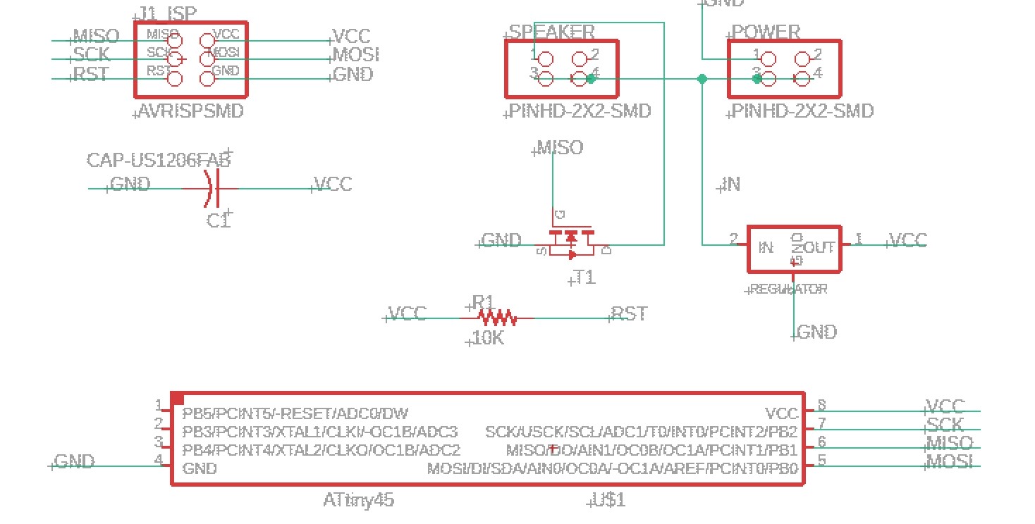
After reading the code Neil created for the speaker output, it became clear that in order to create a sound, the pins of the tiny45 need to be defined and how they will function.
#define output(directions,pin) (directions |= pin) will tell the code which port will be used for output.
#define set(port,pin) (port |= pin) is setting the port pin.
And #define clear(port,pin) (port &= (~pin)) if not mistaken, is to reset the pin and port for any error flags.
The code also goes furter into defining the cycle, delay and the duration. In one ccly als defined are the, amplitude in PWM and steps (I believe this is for the pressure of the frequency wave, or just simply the volume.)
#define cycle_delay _delay_us(10) // 10 us cycle delay time
#define pmin 25 // minimum half period, in cycle delays
#define pmax 500 // maximum half period
#define pstep 0.95 // half period step factor
#define duration 1000 // period step duration
#define amin 100 // minumum amplitude, in PWM units
#define amax 200 // maximum amplitude
#define astep 50 // amplitude step
#define off 255 // amplitude off
Neil defines th MOSFET amplifier's pins as one can see here: #define MOSFET_pin (1 << PB1), here the port #define MOSFET_port PORTB and here the direction : #define MOSFET_direction DDRB
DDRB in hex equal to 0x17 in the datasheet is a memory register in the Tiny45.
Further in the loop, it can be seen Neil calling all the defined headers, in order to make the IC produce sound via the fet amp.
int main(void) {
    //
    // main
    //
    static uint16_t frequency,period,cycle,cycles,delays;
    static uint8_t amplitude;
    //
    // set clock divider to /1
    //
    CLKPR = (1 << CLKPCE);
    CLKPR = (0 << CLKPS3) | (0 << CLKPS2) | (0 << CLKPS1) | (0 << CLKPS0);
    //
    //
    //
    TCCR0A = ((1 << COM0B0) | (1 << COM0B1) | (1 << WGM01) | (1 << WGM00)); // set OC0B on compare match and set fast PWM mode, 0xFF TOP
    TCCR0B = (1 << CS00); // set timer 0 prescalar to 1
    //
    // initialize MOSFET pin
    //
    clear(MOSFET_port, MOSFET_pin);
    output(MOSFET_direction, MOSFET_pin);
    //
    // main loop
    //
    while (1) {
        //
        // loop over amplitudes
        //
        for (amplitude = amax; amplitude >= amin; amplitude -= astep) {
        //
        // loop over periods
        //
        for (period = pmax; period >= pmin; period *= pstep) {
            //
            // loop over square wave cycles
            //
            cycles = duration/period;
            for (cycle = 0; cycle < cycles; ++cycle) {
            //
            // set PWM current on
            //
            OCR0B = amplitude;
            //
            // loop over delay
            //
            for (delays = 0; delays < period; ++delays)
                cycle_delay;
            //
            // set PWM current off
            //
            OCR0B = off;
            //
            // loop over delay
            //
            for (delays = 0; delays < period; ++delays)
                cycle_delay;
            }
        }
    }
}
}
What I did not touch up on are the registers he used, before the loop. I have no real understanding of the registers and how to program them yet. But it is a great way to better learn how to fully utilize the datasheet.
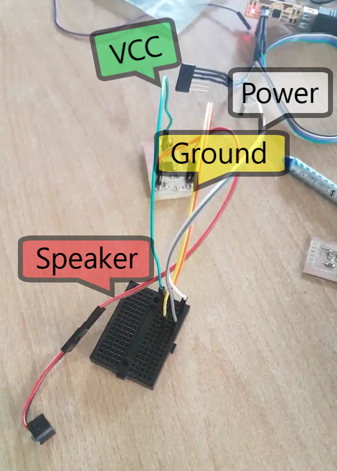
Wiring the speaker to the board.
In this scenario, I was advised to use a breadboard to hook the speaker up to the PCB.
I am using the FabTiny USB to power the board, via the breadboard
For some fun I tried to recreate a well known 8 bit tune with the Arduino Tonemelody sketch
In order to change the pitch, we have to define the notes in the melody with the int melody[]={}.
The sketch also comes with the pitches library and here I looked up some notes online, to hear the tones.
After the notes are defined , we need to define the note duration with this explaination, // note durations: 4 = quarter note, 8 = eighth note, etc.:. so... I tried to make a melody with: