Week assignments
Group assignment
- probe an input device's analog levels and digital signals
Individual assignments
- Measure something: add a sensor to a microcontroller board that you have designed and read it.
Group assignement
You can find documentation about our group assignement on our group page.
Designing a 2*2 switch button matrix
My final project is about to design an electric chessboard. I am still not sure on how to detect chessmoves but I know I am gonna have to use matrix of sensor.
Therefore, I choosed to design a matrix of 4 switch button. This example don't make me save I/O pins since I am still going to need 4 of them but the logic will be the same.
Electronic design
You can get my KiCAD archive for this week here
Below is the schematic used for this week. I helped my self with this arduino tutorial.
The idea of the matrix is to have line i and column i connected if the i*i button is pressed.
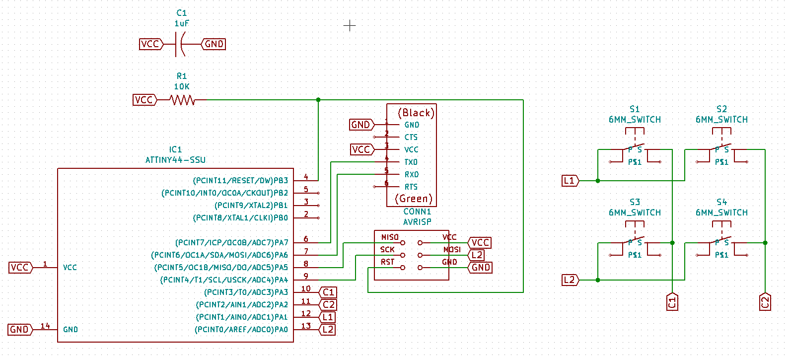
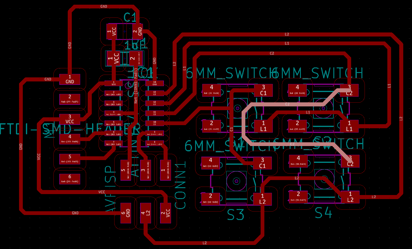
I was struggling with routes drawing in PCBnew thus I decided to move my pins to help myself. But I made a mistake moving L2 label to pin 13 instead of pin 7 where MOSI is supposed to be connected to AVR header. Hoppefully this mistake was easily solvable by using RXD pin of the FTDI header.
I realized this week in PCBnew that drawing the routes can become complicated with many components. Eventually I found a solution to my design but I forgot one route highligted in white below. Thus, at the end I had to add a jumper wire.
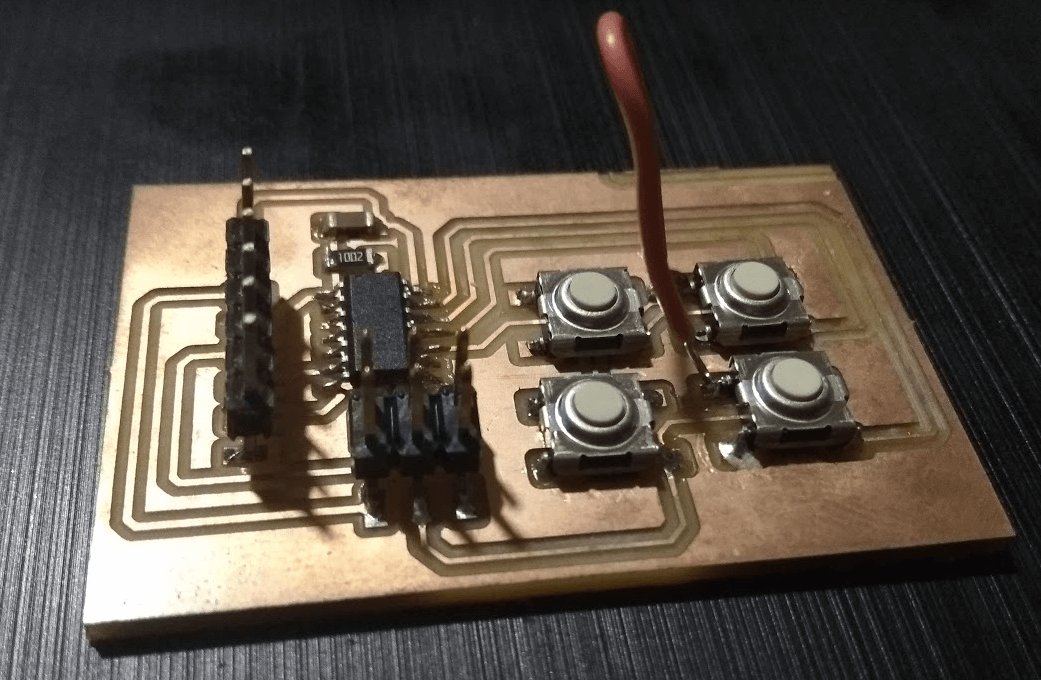
The board milled very fine and I was able to solder my components
Testing FTDI monitoring
My first trial was to be able to receive a serial information through FTDI cable, thus I tried this code:
#include <SoftwareSerial.h>

#define RX    7   //*** correspond to TXD FTDI header pin
#define TX    6   //*** correspond to RXD FTDI header pin

SoftwareSerial MySerial(RX, TX);

void setup() {
  MySerial.begin(9600);
}

void loop() {
  Serial.print("FTDI test");
  delay(2000);
}
At first I reversed RX and TX pin because I didn't understand well how the library was working. But we actually have to be in the shoes of the computer and not them of the board.
After this correction the code was working well.
Programming one button
I wanted to try first the behaviour of the board programming only one button. Here is my code:
#include <SoftwareSerial.h>
#define RX 7
#define TX 6
SoftwareSerial MySerial(RX, TX);
const int l1 = 1;
const int c1 = 3;
void setup() {
pinMode(l1, INPUT); //The l1 pin will go to high if c1 goes to high
pinMode(c1, OUTPUT);
MySerial.begin(9600);
}
void loop() {
digitalWrite(c1, HIGH);
delay(1000);
if (digitalRead(l1)==HIGH) { //since h1 and l1 pins are connected id the button is pressed, I can test l1 state.
MySerial.println("Button pressed");
delay(2000);
}
else {
MySerial.println("Button not pressed");
delay(2000);
}
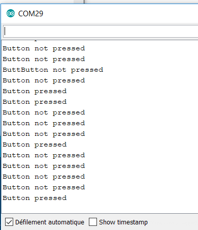
}This code was working fine. Below is the result. But here only one button was soldered. I will realize in the next step that it is not consistent to do it this way.
Programming with four button
Detecting the lines
To detect a button, you have to know its line and column. First step is to detect the line:
#include <SoftwareSerial.h>

#define RX    7   // *** D3, Pin 2
#define TX    6   // *** D4, Pin 3

SoftwareSerial MySerial(RX, TX);

const int l1 = 1;
const int l2 = 0;
const int c1 = 3;
const int c2 = 2;

// the setup function runs once when you press reset or power the board
void setup() {
  pinMode(l1, INPUT_PULLUP); //using INPUT_PULLUP activate the pull resistor and the input is now normally HIGH
  pinMode(l2, INPUT_PULLUP);
  pinMode(c1, OUTPUT);
  pinMode(c2, OUTPUT);
  MySerial.begin(9600);
  MySerial.println("Start");
}

// the loop function runs over and over again forever
void loop() {
  digitalWrite(c1, LOW); //The logic is reversed compared to 1 switch test to make it consistent
  digitalWrite(c2, LOW);
  delay(200);
  if (digitalRead(l1)==LOW) { //Since the pullup resistor is activated I now have to detect when l1 pins goes low
    MySerial.println("Line 1 pressed");
    delay(200);
  }
  else if (digitalRead(l2)==LOW) {
    MySerial.println("Line 2 pressed");
    delay(200);
  }
}
I reversed the logic in this code compared to the 1 switch test. Indeed, with the 4 buttons soldered, voltage to l1 pin was not LOW, it was about 1.5V and detected as HIGH. Using the built-in pullup resistor allowed me to have a consistent 5V when button is not pressed and a consistent LOW when button is pressed. This code is working well.
Detecting the button
Still troubleshooting this part.