Mechanical & Machine Design
The goal for this week's assignment was to design a machine that includes mechanism, actuation and automation. Bulid the mechanical parts and operate it manually. Since this is a group project you can find the enitre documentation of our robotic arm on our Group Assignment Website.
Brainstorming
We've had some ideas for this assignment: Juicer, Fab-Tour Bot, Robotic Arm. For each of them we created a concept before we decided what to do.
Juicer: Requirements
Fab-Tour Bot: Requirements
Robotic Arm: Requirements
After spending weeks on deciding what to make ranging from an Juicer to a Fab-tour Bot, we finally decided on making the Robotic Arm.
Robotic Arm: Technical Concept
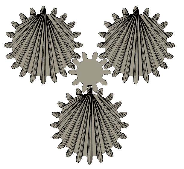
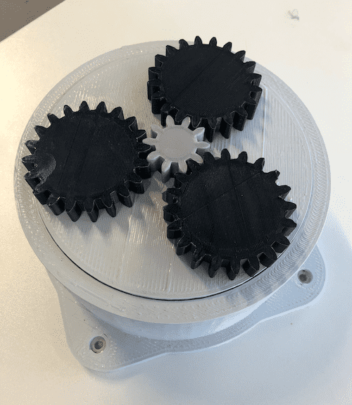
Mechanical Design: Planetary Gears
Any planetary gearset has three main components:
Each of these three components can be the input, the output or can be held stationary. Choosing which piece plays which role determines the gear ratio for the gearset.
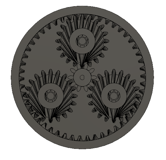
In this case, the planet wheels and the planet carrier are the ones that are kept stationary, while the ring gear is the one that moves. Planetary gears are often used when space and weight are an issue, but a large amount of speed reduction and torque are needed. For this reason I decided to use planetary gears, because the bottom part has to carry the whole weight of the arm.
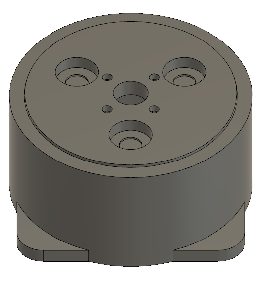
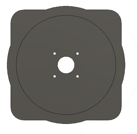
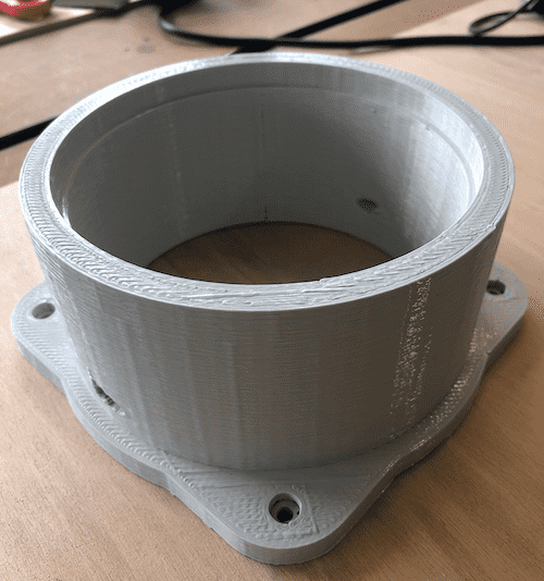
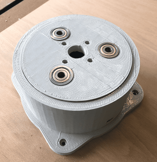
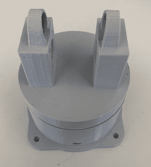
Robotic Arm Bottom Part
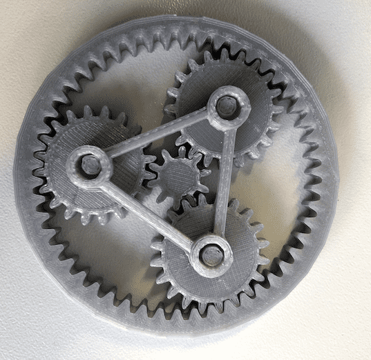
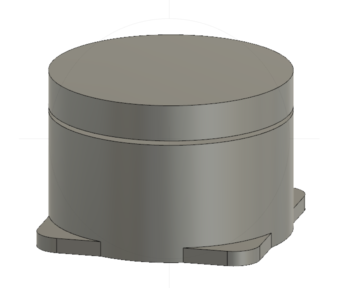
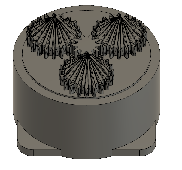
The goal was to let the arm pick up something and move it to somewhere else. I decided to design the bottom part and as well some gears. I found this beautiful planetery gearset on Thingiverse and modified it to my needs. This gearset is able to to distribute the weight among several gears. To create the design I used Autodesk Fusion 360. To get a full introduction on how to use Fusion 360 got to the Computer-Aided Design assignment. Below you can see the finished design of the bottom part. Three placeholders for three ball bearings were taken into account in the design. In this way, the weight is not transferred to the supporting gears but to the ball bearings, which can withstand much more pressure. In addition, this technology prevented the stepper from carrying the entire weight.
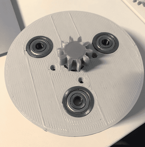
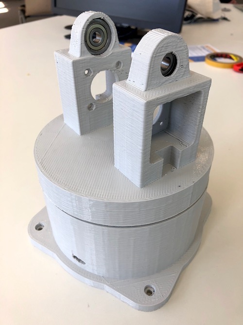
3D Printing
I used the BigRep to print the parts. Before I printed the gears with the Ultimaker using a 0.4 nozzle. Before I printed them, I made a test print to check the tolerance between them. For more informations how to use a 3D printer go to the 3D Scanning and Printing week.
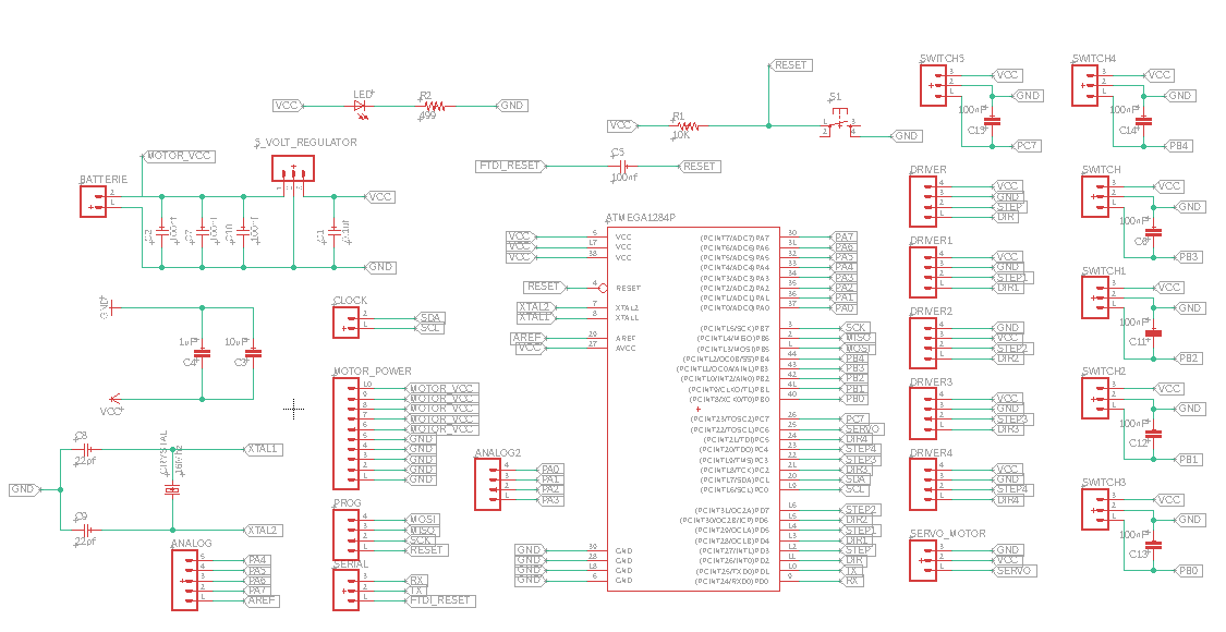
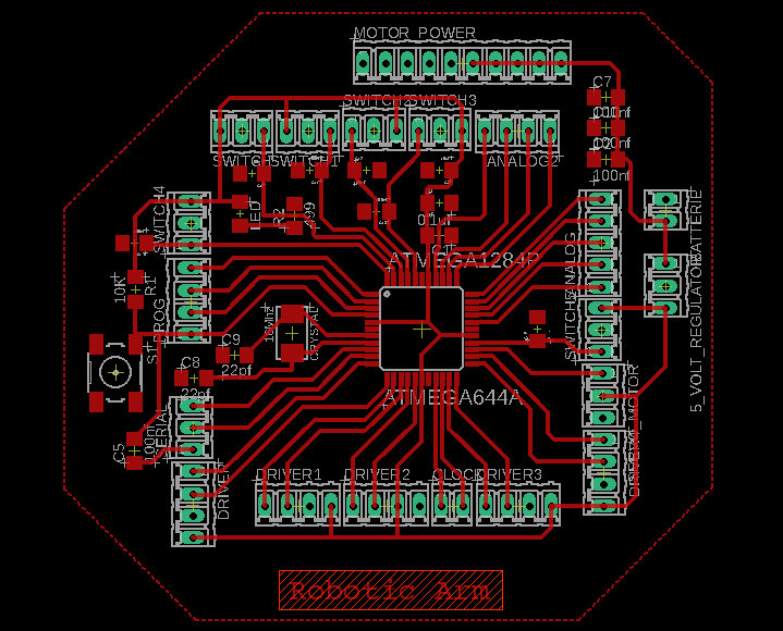
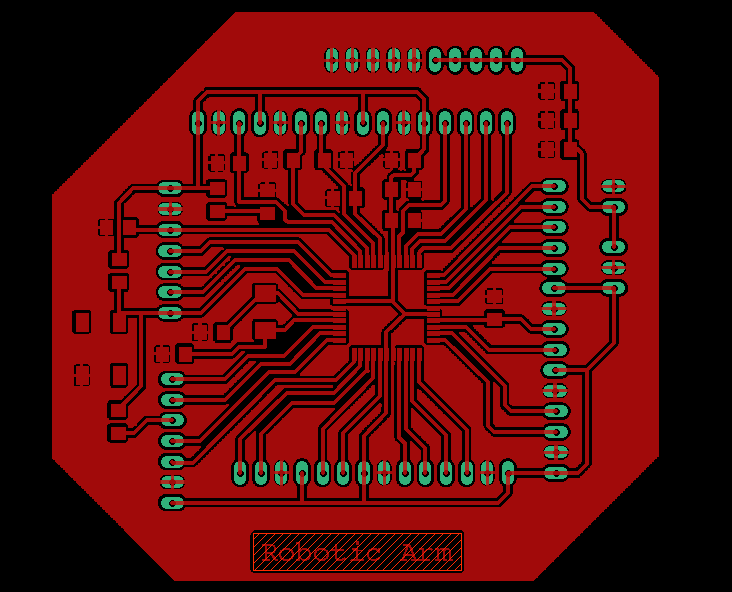
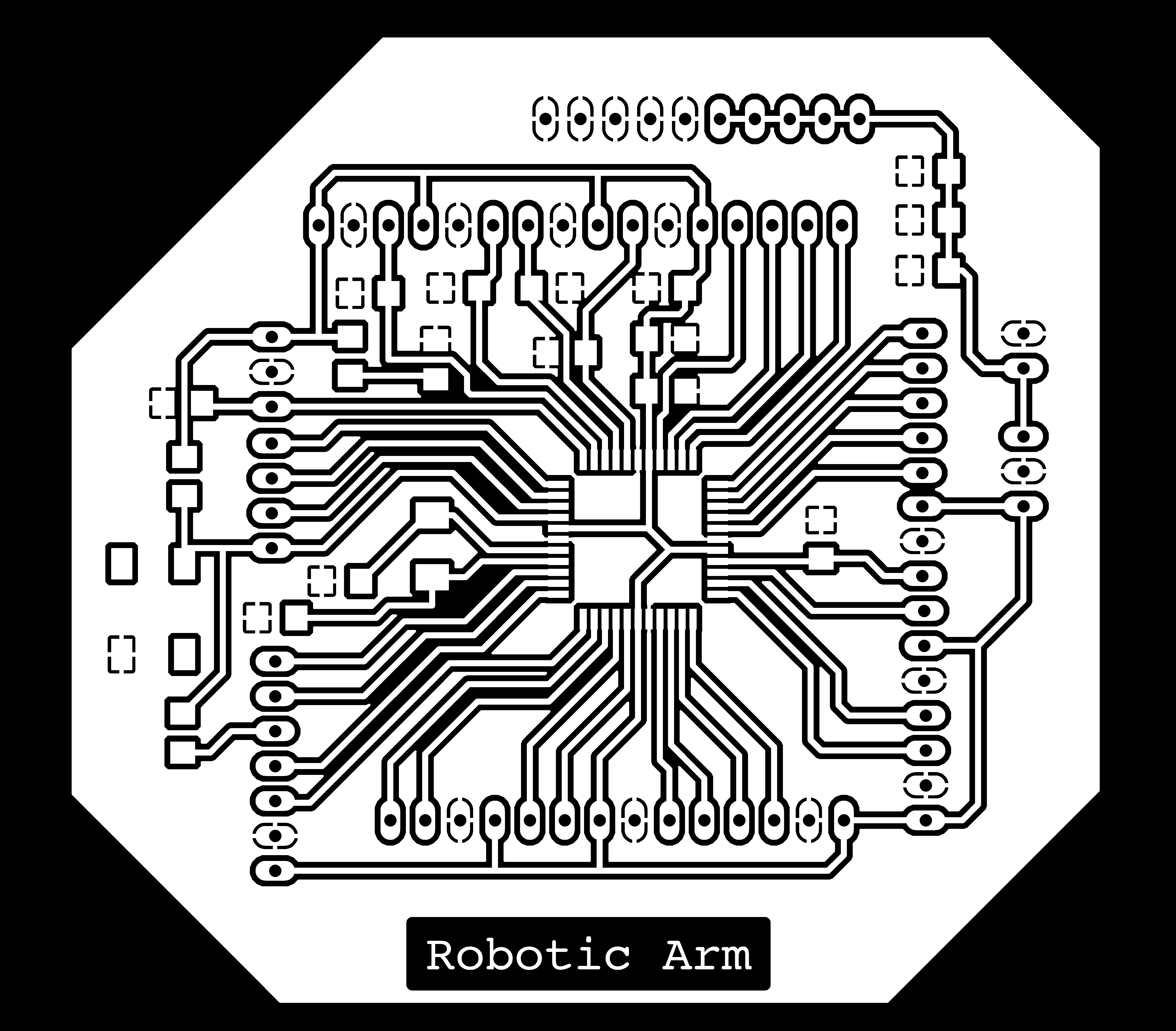
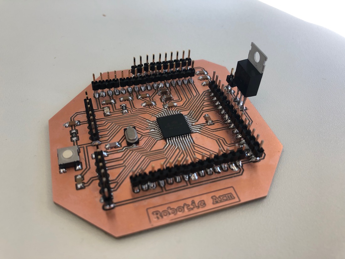
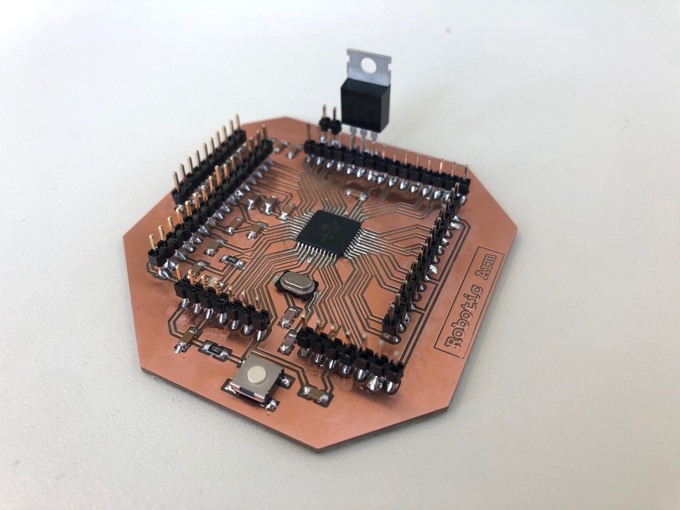
Schematic & Board Layout
I also created the microcontroller board for this week's assignment. I decided to use a Atmega1284, since it has more pins and we are going to use 5 stepper motors and one servo motor. To get a full introduction on how to make a Schematic and Board Layout with Eagle go to the Electronics Design week.

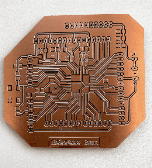
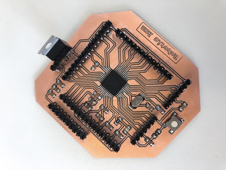
Milling & Soldering
After generating the G-Code for the Roland Mill I started the job. To read more about how to generate the G-Code and how to use the Roland Mill go visit the Electronics Production page.
Programming
This basic code rotates the bottom part of the robotic arm as soon as you enter a value into the serial communication.
// defines pins numbers
const int stepPin = 3;
const int dirPin = 4;

// Stepper Travel Variables
String incomingData;   // for incoming serial data
int val = 0;	// parse the incoming data to an int

int enable = 13;

void setup() {
  // Sets the two pins as Outputs
  pinMode(stepPin,OUTPUT);
  pinMode(dirPin,OUTPUT);
  pinMode(enable,OUTPUT);
  digitalWrite(enable,HIGH);	//disable the motors
  digitalWrite(dirPin,HIGH);	//rotates the motor clockwise

  Serial.begin(9600);  // Start the Serial monitor with speed of 9600 Bauds

// Print out Instructions on the Serial Monitor at Start
  Serial.print("Enter Move Values Now: ");
}

void loop() {

 if (Serial.available() > 0) {

                incomingData = Serial.readString();
                val= incomingData.toInt();
                Serial.println(val);
                digitalWrite(enable,LOW);	//enables the motor

        }

  if (val > 0 ) {
  // Makes 800 pulses for making one full cycle rotation
  for(int x = 0; x < val ; x++) {
    digitalWrite(stepPin,HIGH);
    delayMicroseconds(500);
    digitalWrite(stepPin,LOW);
    delayMicroseconds(500);

   }
   val = 0;
   digitalWrite(enable,HIGH);
   }
}