Week 16
Mechanical Design
The group assignment for this week was to design a machine that includes mechanism+actuation+automation, to build the mechanical parts, operate it manually and to document the group project and our individual contribution. This page describes the individiual contribution and the page on the below link describes the entire process.
Complete Documentation of our Group Project
Braille Printer - Conceptual Mechanism
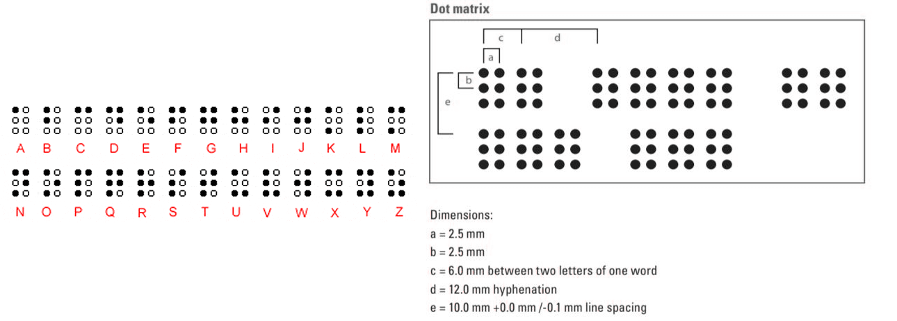
Braille is a tactile writing system used by people who are visually impaired. The characters have rectangular blocks called cells that have tiny bumps (or dots) seperated by standard distances. Below images show the english alphabets in braille and the standard distances.
Our aim was to design a machine with a paper feed mechanism, mechanism to move the printing head along one axis and another mechanism to control the actuation of the end effector. The end effector was decided to be a solenoid with a sharp end to pierce holes on the paper, with the holes making the braille script. Me and abhilash opened up an old dot matrix printer to get its solenoid out, and collected reusable parts from the opened printer and disposed parts in the lab. However, the solenoids were too small and didnt suit our application. We learned about the limit switch by opening up the old printer and also got familiarised with paper feed mechanisms.
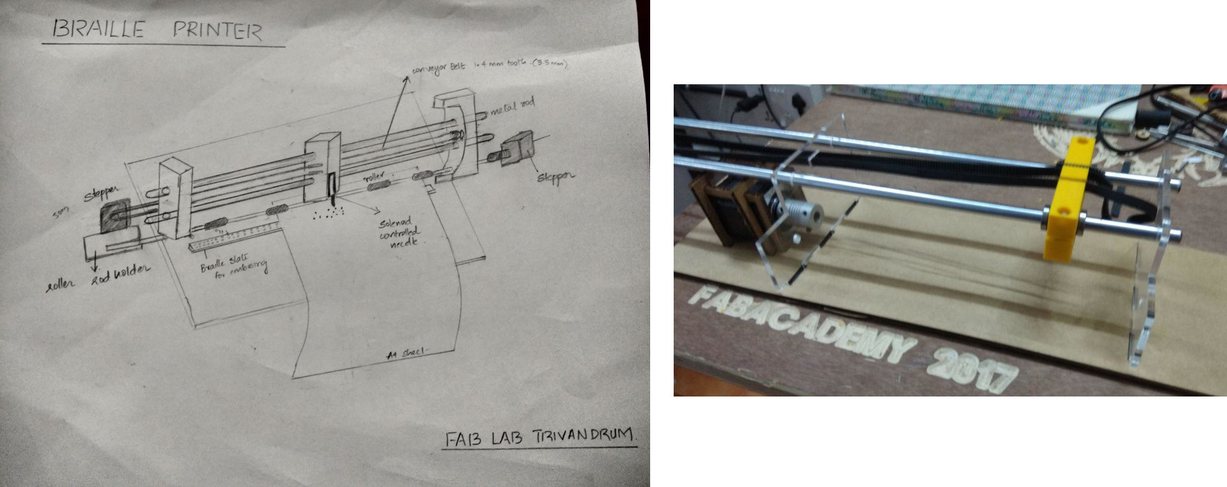
We observed the projects done by students of previous years and the ongoing projects at our lab. This helped to get familiar with the integral parts of a machine like the linear bearings, belt and pulley, smooth rods, motor coupler, limit switch, types of arrangement of screws etc. This helped us in making the initial sketch of the Braile Printer. The stepper motors were kept on either side to balance the weight.
Myself, Amit & Rinoy prepared the inventory required for the machine.
We listed out the initial parts consisting of the following.
1. Solenoid
2. Stepper motors - 2Nos
3. GT2 betl with 1.4mm tooth
4. Linear bearings -2 Nos
5. Motorshaft-Belt Coupler - 2 Nos
6. Pulley - 2 Nos
7. 8mm smooth rod - 2 Nos
8. Paper feeder rod with the rubber bush
9. Limit switch
Since the other parts were available at the lab, the availability of linear bearings and the solenoid in local shops were checked. We got the linear bearings but not the solenoid. This made us to order a Solenoid (Push Pull Linear Actuator) over the internet. We had to wait for it's arrival for getting the exact measurements. The linear bearings helped us to have our initial dimensions of the side supports and the end effector head which moves over the smooth rod on the bearing. The initial sketch was then developed into the one below with designed dimensions by amit taking care of the acrylics and akhila 3d printing the initial dimensions of the end effector head.
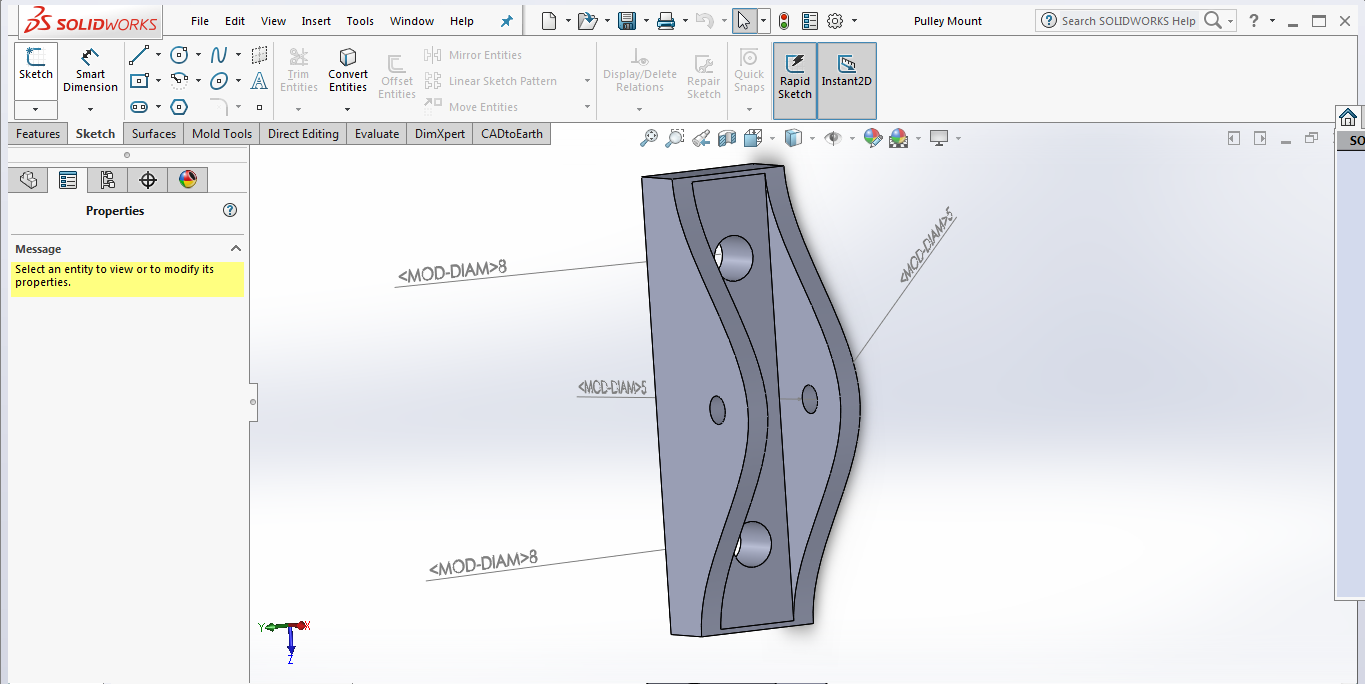
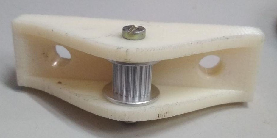
Designing & 3D Printing a pulley holder
The smooth rods (along which the end effector moves) were stacked horizontally in our intial sketch, with the belt in between. We were in need of a suitable arrangement to hold the pulley. The below part was hence designed in SOLIDWORKS and 3D printed.
Download the Design Files
The below video shows the holder during simulations.
Designing a clamp for the stepper Motor
The next requirement was to hold and place the stepper motors to either sides. The two motors had to be perpendicular to each other with one driving the paper feed mechanism and the other moving the end effector. appropriate mount for holding the stepper motors was another requirement for which the following part was designed.
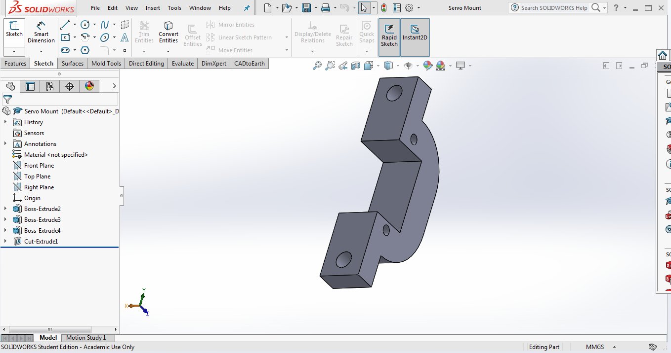
Download the Design Files
The design was later improved by vishnu and amit and the final mechanical design came out to be as the one below.
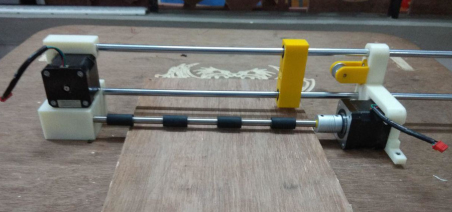
In addition to the above, i provided the measurement inputs for the design, involved in the assembling and testing of the parts and giving feedbacks to design.