Group assignment

Compare the performance and development workflows for other architectures

The group Assignment link can be found here: Week 9 Group Assignment

Individual Assignment

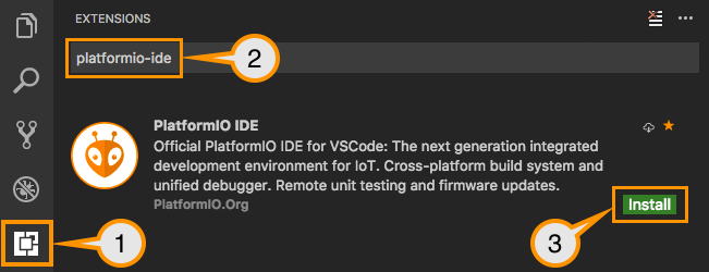
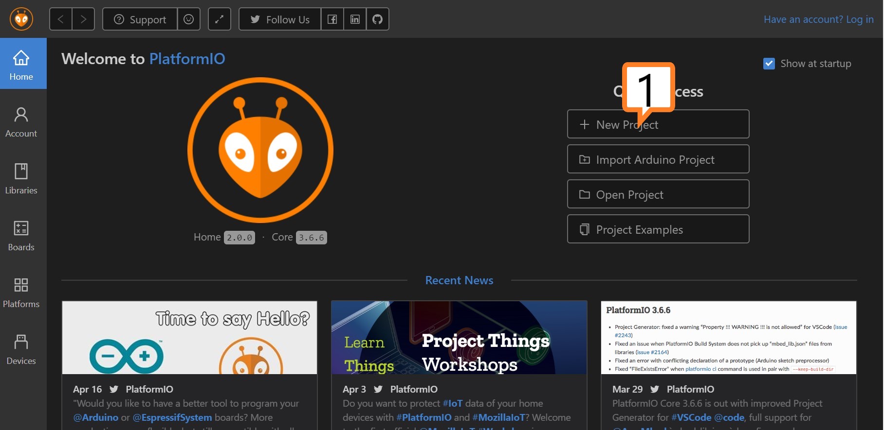
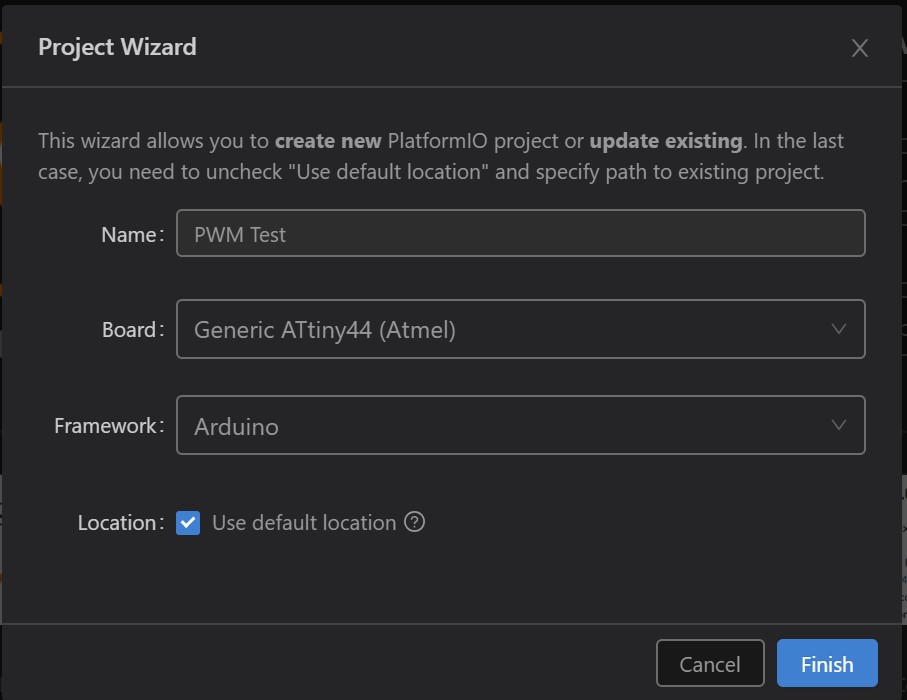
Read a microcontroller data sheet, program your board to do something, with as many different programming languages and programming environments as possible

ATTiny Boards

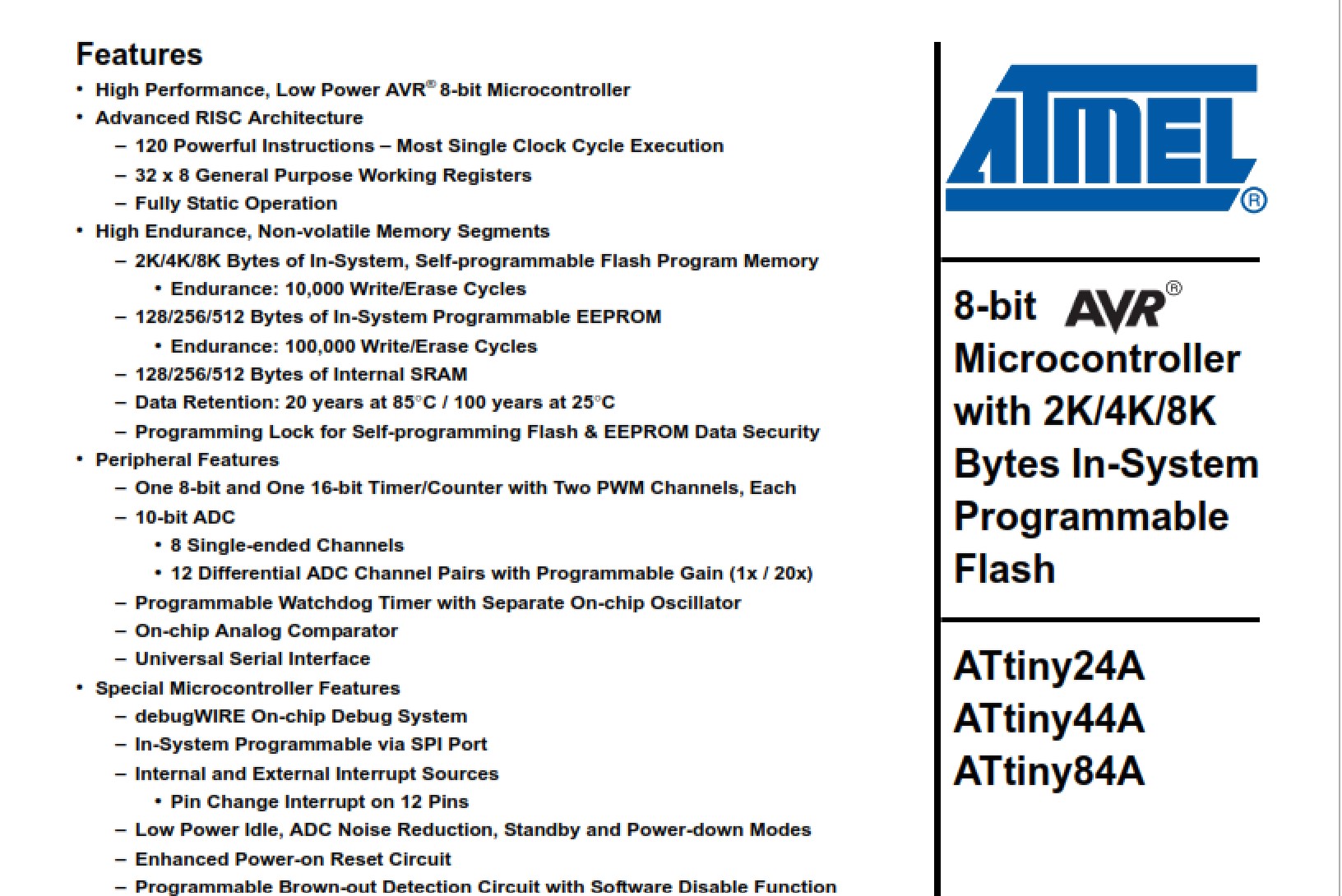
ATTiny boards Features


I had no idea, reading a datasheet was like trying to learn from a Klingon or High-Elf or what have you and now I know how a layman feels, when I lay down the IT jargon on them.

It is in no way an easy read, it takes time and lots of looking terms up, if you are unfamiliar to the abbreviations. Even if it is for a global read.

However, it is a great source for understanding how the ATTiny ICs work.


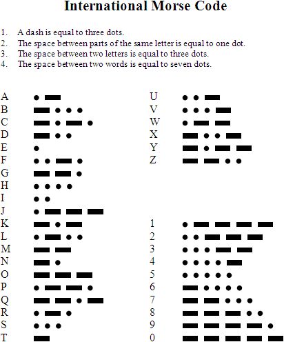
I used the datasheet to read the pin layout for week 7 and further understood the PWM feature.

ATTiny Boards

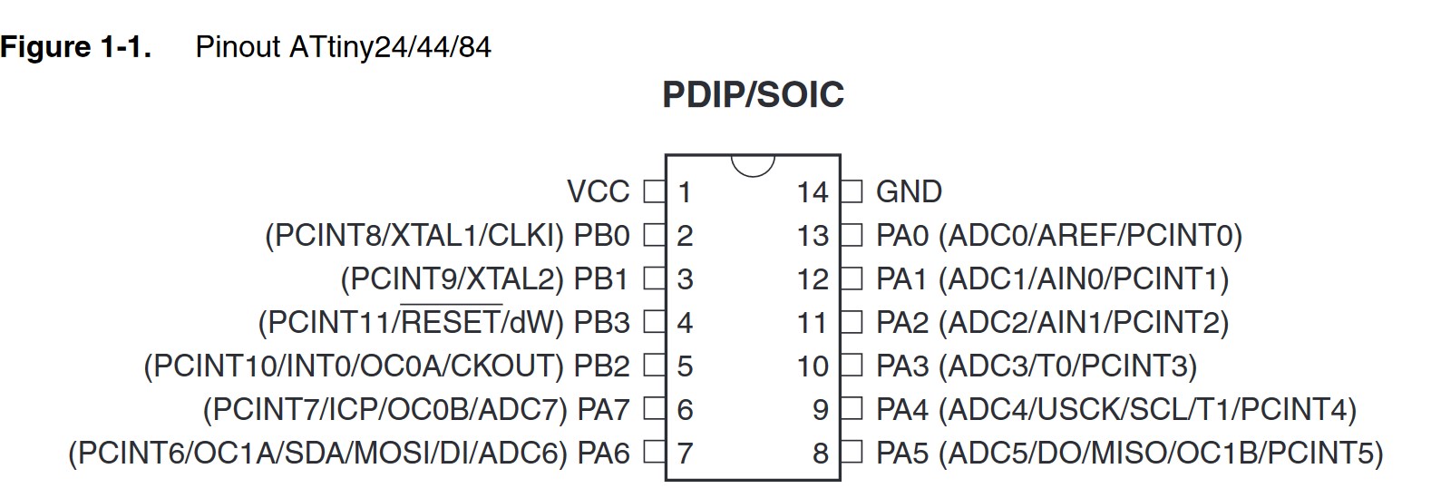
ATTiny SMD/SMT Pin Layout
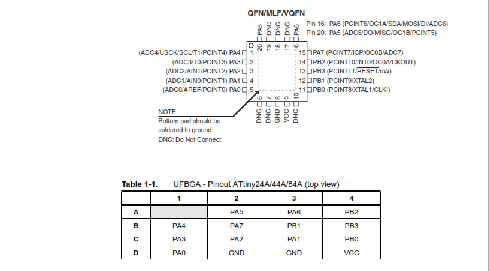
ATTiny Boards

QFN....whaaaa?

*Ahem* Quad Flat No-leads Package Wiki


From my understanding in laymans terms, is that the ATTiny ICs are powerful 8Bit silicons with no to little overhead in processing instructions.

This of course is derivable from the RISC (Reduced instruction set computer) architecture, which Stanford and Berkley developed (or at least made popular) in the '80s and are perfect for embedded systems.

Further, the datasheet also explains how the pins are grouped.

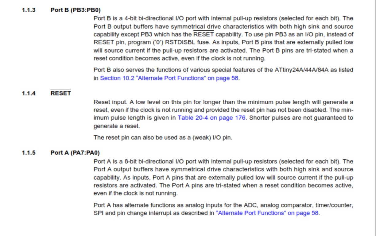
The B ports are a 4-bit bi-directional I/O ports with internal pull-up resistrors. All B ports, except for PB3 (which has the RESET capability), have symmetrical driver characteristics with both high sink and source capabilities, whilst the A Ports are 8-bit bi-directional.

Port A has alternate functions as analog inputs for the ADC, analog comparator, timer/counter, SPI.

errorbootload

The Datasheet explains how the pins are grouped.

The pin layouts are described in groups between the PB and PA.

  • The VCC and GND are the common pins and are located on pin 1 and pin 14 respectively
  • Master Output Slave Input is assigned to pin 7 (PA6)
  • Master In Slave Out is assigned to pin 8 (PA5)
  • Serial Clock is assigned to pin 9 (PA4)
  • Reset is assigned to pin 4 (PB3)

Block Diagram

ATtiny24A/44A are low-power CMOS 8-bit micro-controllers based on the AVR enhanced RISC architecture.

Attiny44A has 12 general purpose I/O lines, 32 general purpose working registers. The main function of the CPU core is to ensure correct program execution. The CPU must therefore be able to access memories, perform calculations, control peripherals, and handle interrupts.

Then the Architectural view is as shown below:
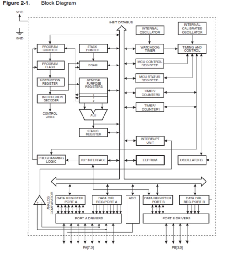
errorbootload

The Block Diagram


The CPU Core

The main function of the CPU core is to ensure correct program exection and must be able to access memories, preform calculations as an example.

And in order to maximize the performance and parallelism, the AVT uses a Harvard architectrue, with seperate memories and buses for program and data.

errorbootload

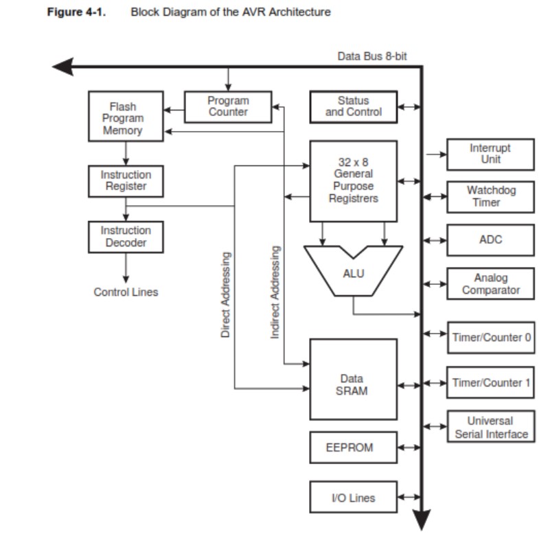
The AVR Block Diagram

Instructions in the Program memory are executed with a single level piplining as you can see in the image above.

Now I am by no means a better embedded programmer by reading the datasheet, but I have learned that the MCU of the Atmel ATTiny series is capable of being used in a pletohara of applications.

And in my case, a capacative touch sensing( I hope) midi player, with strings made of a conductive paint.


What Questions do I have, regarding the Datasheet?

Lots, to be honest, but to hone in on my main concern, how far can a single MCU go in controlling several boards?

The more refined question perhaps is, can the ATTiny series IC, control 3 boards simultaniously? i.e. A capacative strumpad, MIDI controller and MIDI board?

If it is not the ATTiny series, then maybe perhaps the ATMega series?

Guess, I will have to find out, eh?

Programming the Board

Burn the bootloader to the PCB

In order to burn the bootloader to the PCB, I first needed to install the ATTiny44/A drivers on my laptop.

I used the drivers provided by Adafruit at this link

After installing the drivers, I opened the Arduino IDE, selected the "Tools" menu and navigated to the boards manager.
This can be found when hovering over "Board" , above "Processor".

When the manager window pops up, I filtered the ATTiny boards, by entering attiny in the search bar.

ATTiny Boards

ATTiny boards installed


Now, we can configure the IDE to burn the bootloader to our board and in order to configure the IDE, we need to have read the datasheet at least once in order to understand what we are doing.

The settings are as following:

  • Board: ATTiny 24/44/84
  • Processor: ATTiny 44
  • Clock: 20 MHz
  • Programmer: USBtinyISP

Double check, to see if your settings are correct and select Burn Bootloader

I recieved and error, stating that the connections might the issue.

errorbootload

Error burning bootloader.

After checking the solder, it seemed that there was a damaged track. After soldering a piece of leftover Cu, the bootloader was succesfully installed.


Blink the LED

In order to get aquinted with the programming, I opened a few samples, that come with the IDE.

These can be found under the File Examples and built-in examples.

I loaded up the sketch code, just out of curiosity if the LED would do as it is told and sure enough, it was blinking.

errorbootload

Quick look at the code.


Program the LED to turn on or off with a switch/button

Again, you can use the built in examples to learn and understand. Loaded the code up to the board and the LED turned on as long as the button was pressed.

errorbootload

The Button example.

Using the PWM of the ATTiny44

After the examples, I decided to use the PWM for simulating an analog potentiometer. With this I can controll the LED brightness with a few clicks.

I had some issues, with the button not alwasys turning on the LED. I concluded that it was a button bounce, which created this and used a bool (true,flase) param, in order to elimante this.

Here is the code in text:

int switchPin = 3;
int ledPin= 8;
boolean lastButton = LOW;
boolean currentButton = LOW;
int ledLevel = 0;

void setup()
{
  pinMode(switchPin, INPUT)
  pinMode(ledPin, OUTPUT);
}

boolean debounce(boolean last)
{
  boolean current = digitalRead(switchPin);
  if (last != current)
{
  delay(5);
  current = digitalRead(switchPin);
}
return current;
}

void loop()
{
  currentButton = debounce(lastButton);
  if (lastButton == LOW && currentButton == HIGH)
{
  ledLevel = ledLevel + 51;
}
lastButton = currentButton;

if (ledLevel > 255) ledLevel = 0;
analogWrite(ledPin, ledLevel);
}
                    

And here is the .ino download link:

The PWM Code


Hilfe Mich. Programming the LED to flash S.O.S Morse

I wanted the LED to flash Morse code, S.O.S and in order to do that I first had to read up on the conventions of Morse Code.

errorbootload

Morse Alphabet.

//SOS for LED, when pressed by Button:
int ledPin = 8;
int switchPin= 3;
int val = 0;
int s = 300;
int o = 800;

void setup() {
  pinMode(ledPin, OUTPUT);
  pinMode (switchPin, INPUT);
}

void character(int speed) {
  digitalWrite(ledPin, HIGH);
  delay(speed);
  digitalWrite(ledPin, LOW);
  delay(300);
}

void loop() {
  val = digitalRead(switchPin);
  if (val==HIGH) {
  digitalWrite(ledPin, LOW);
  for (int x = 1; x <= 3; x++) {
  character(s);
}
delay(100);
for (int x = 1; x <= 3; x++) {
  character(o);
}
delay(100);
for (int x = 1; x <= 3; x++) {
  character(s);
}
delay(2000);
}
else{
  digitalWrite(ledPin,LOW);
}
}
                    

I will go a bit into detail how I wrote the code and how some statements have been used.

The “for” statement
The “for” statement is used to repeat a block of statements enclosed in brackets. An increment counter is usually used to increment and terminate the loop. The “for” statement is useful for any repetitive operation, and is often used in combination with arrays to operate on collections of data/ pins.
There are three parts to the “for” loop header:

  • Initialization
  • Condition
  • Statement

So for the “for“ statement in the sketch:

for(int x = 1; x < 3; x++){

}
                                      

Step 1: Integer (whole numbers) value of variable x as 1
Step 2: Evaluate if x is less than 3.
Step 3: If it is valid, execute the following statement
Step 4: x increases and becomes 2.
Step 5: Repeat Step 2 less than 3.
Step 6: Repeat step 3
Until x = 3, the condition of x < 3 is not valid then the program skips over the code.
We set x < 3 to have it repeat 3 times. Calculating from 0 to 2, it repeats 3 times.
If we wanted it to repeat 100 times, we can use the following code: for(int x = 0;x < 100;x++){}
Some comparison operators like ">", " < " are frequently used in programming conditional statements. They will covered in more detail in the next section.

This is a section of a tutorial found here: DFrobot blog

I combined the button code with the Blink code, in order to flash SOS whenever the button is pressed.

Download the The SOS Code here.


Embed C using VSCode and PlatformIO

I decided, that the Arduino IDE is a good way to code for your Arduino based platform, but wanted to know if there was an alternative with VSCode, just to keep it in line with one IDE.

Surely enough an online search brought me to PlatformIO

This is an open source ecosystem fo IoT development in mind. It is cross-platform so jumping from OS to OS makes it much easier for IoT developers.

In order to install it, I could just lookup PlatformIO in the extensions section of VSCode, install it and run it.

install platformio

Install PlatformIO VSCode.

install platformio

Create New Project

install platformio

Select the MCU, Framework and of course the name of your project

install platformio

Wait for Initialization to complete.

install platformio

Initialization completed.


Now we can code the code, that we want to upload to the board. This uses c/cpp extensions.

It is rather quick to upload your code to your board as it is mostly automated process, but for sanity and a more granular control's sake, we can always edit the config if and when needed.

install platformio

Wait for Initialization to complete.