6. 3D Scanning and printing
Abstract
This week, I have a group assignment and individual assignment. Group assignment consists of test the design rule for your 3D printers. We are started with a known Design from thingiverse. We have several 3D printers in the Oulu fab lab; we are decided to do print at least 3 of the 3D printers such as Stratasys Fortus 380MC 3D Printer, FormLabs Printer, [LeapFrog 3D Printer]https://www.lpfrg.com/) and Sindoh 3D VOX Printer. The individual assignment consists of two-part, the first part is design and 3D print an object (small, few cm3, limited by printer time) that could not be made subtractively. The second part of the individual assignment is 3D scan an object (optionally print it). My first part of the individual assignment is to design and print particle in a box model 3D printing. I have first-time use Fusion 360 educational version software for my 3D design. The second part of my assignment, I choose my son’s toy Duck and Xylophone I have captured set of images from my camera and use it in the Autodesk Recap to create 3D data from the captured images. I also install Autodesk Recap educational version for a 3D scan of an object. I also tried 3DSCANN mobile application for making the 3D models from pictures.
Group work
Design rule of your 3D printers
1) Stratasys Fortus 380mc
It uses ABS (Acrylonitrile butadiene styrene). It is based on the Fused Deposition Modeling (FDM) technology. It is an additive manufacturing process which prints from bottom to top, layer-by-layer. The ‘Insight’ software is used as the printing software.
2) Leapfrog Printer
The software used for this printer was slic3r and the material used in this printer is PLA and PVA (water-soluble support material) is used as the support material. One important feature with this printer is that it can be used to print with different colors.
3) Sindoh 3D Vox
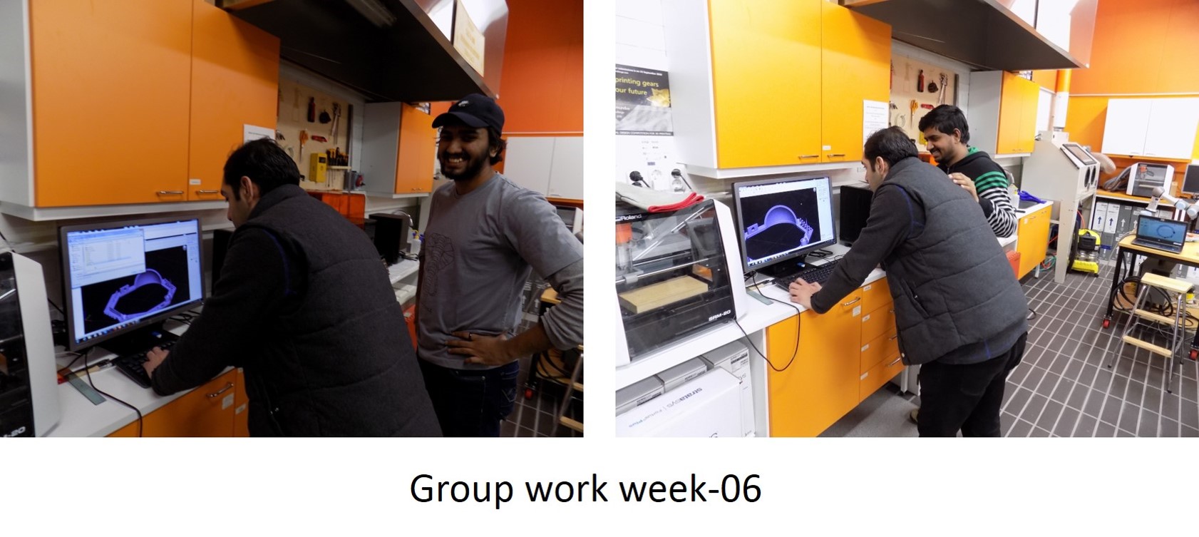
It uses PLA (Polylactic acid). The technology used in this printer is fused filament fabrication (FFF) which is a 3D printing process that uses a continuous filament of a thermoplastic material. This printer supports Ply. Obj, STL. file formats. The filament material used in the printer change its state based on the melting point and 3D printer will put the layers on top of each other till the design is made. ABS or PLA used as the material. Software used is Sindoh 3DWOX. We opened our design from the 3DWOX and made the tool path first. Then, made the support material ‘none’ in order to check the printing boundaries of the printer. This week group work regarding test the design rule of your 3D printers. I worked together with Sahan and Yasir. Some of the group pictures are shown below.
The first step is to download the test 3D print file (stl) from Thingiverse. A screenshot of the desktop is shown below,
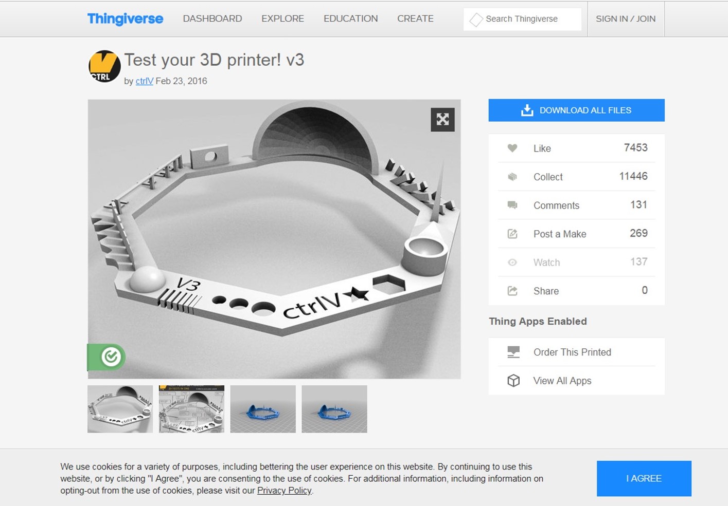
The advantages of this test file, which test various printing task such as various holes, sharp edges, name, hole in the wall, spike, nut and so on.
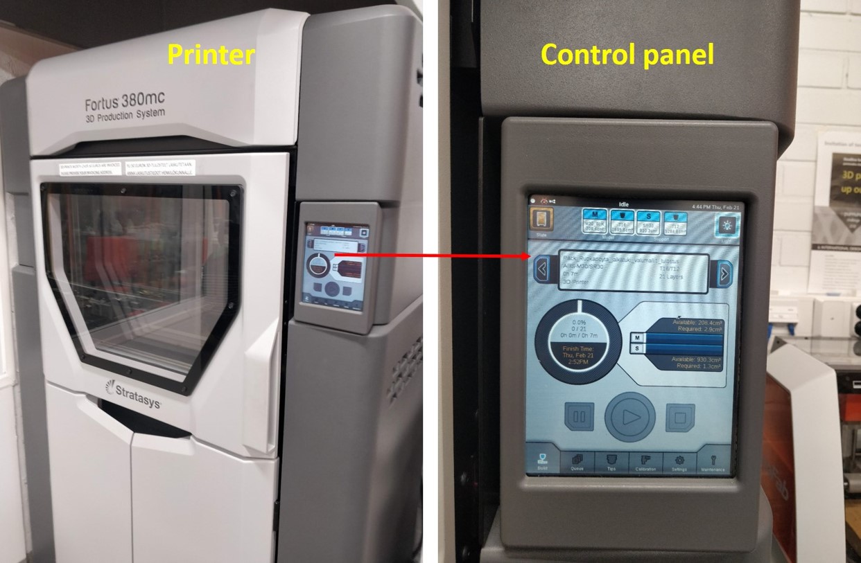
First, we 3D print using Stratasys Fortus 380MC 3D Printer. The technology used is Fused Deposition Modeling (FDM). It is an additive manufacturing process based on the bottom-up approach. Layer by layer deposition of the model and support materials. The maximum build size is 355x305x305 mm for this printer. Typical layer height is 50 to 400 microns. The material used is commercial ABS (Acrylonitrile butadiene styrene) which is high strength, temperature resistant and more susceptible to warping. Below figure shows the image of the printer and its control panel used.
Software used for control the printing process is Insight. The step by step process is described below
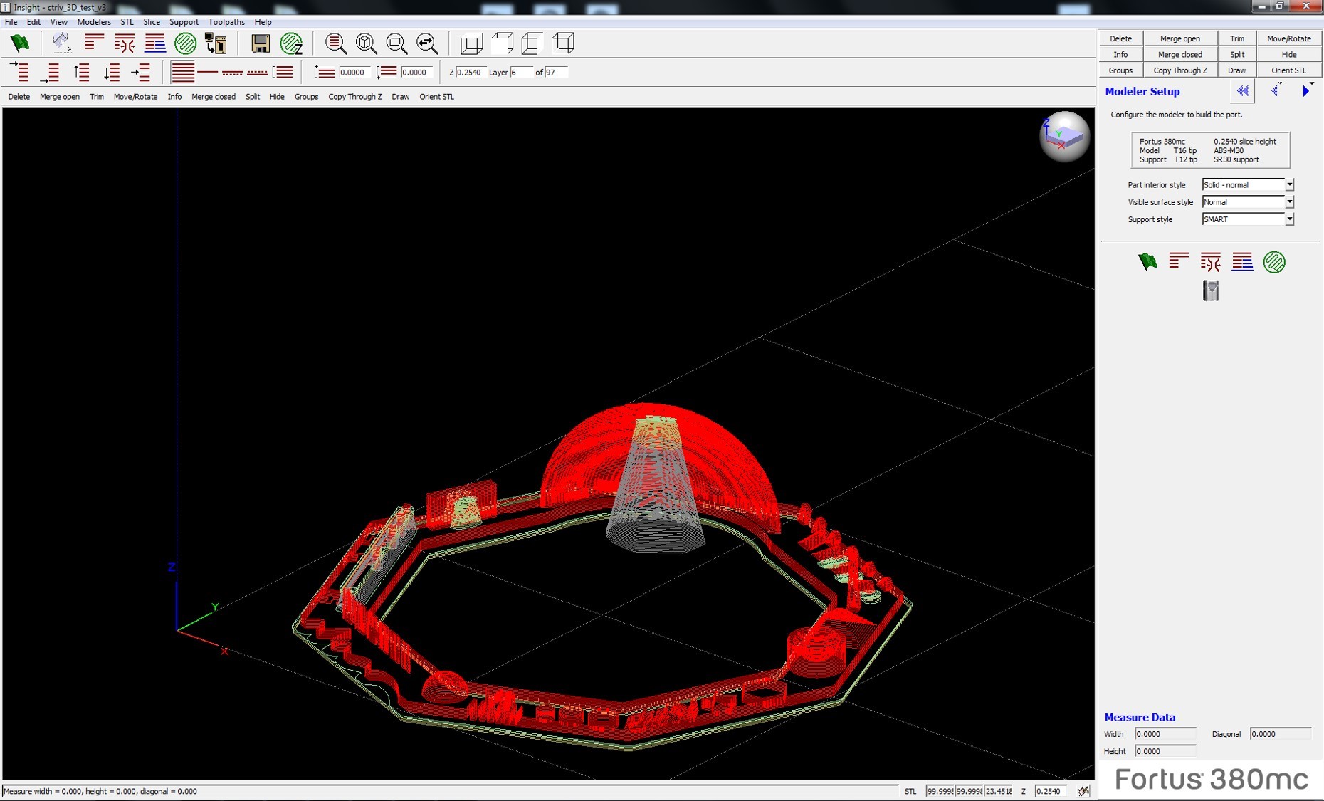
Step-1: Open the CtlV_3D_test_V3.stl (previously mentioned) file in the Insight software. See the screenshot below
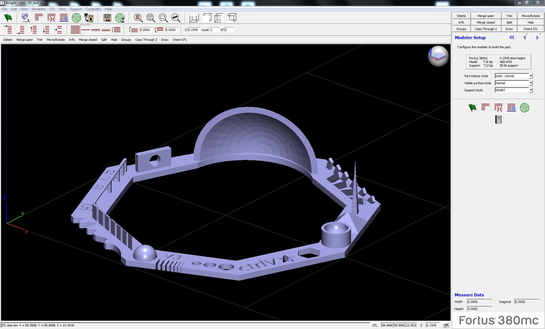
We use the default setting to set up printing, part interior style was-solid normal-, the surface style was –normal- and support style was –smart-. Followed by press finish and screenshot are shown below figure.
Design move to the corner position
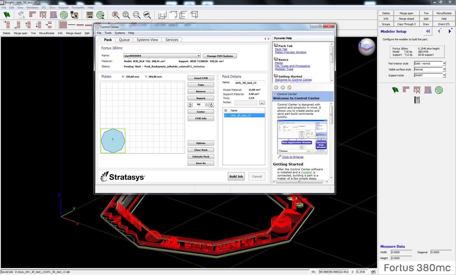
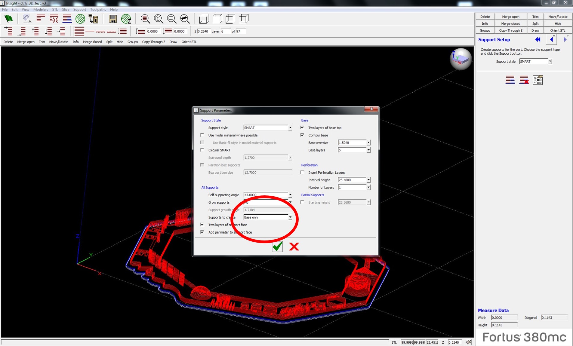
Without support material
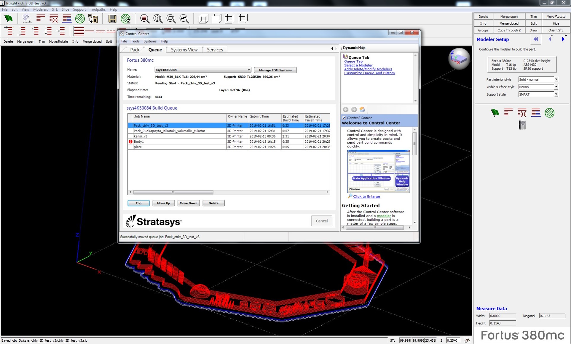
Estimated time for printing the whole structure is 33 minute
The printed design with support material and without support material is shown in the below figures.
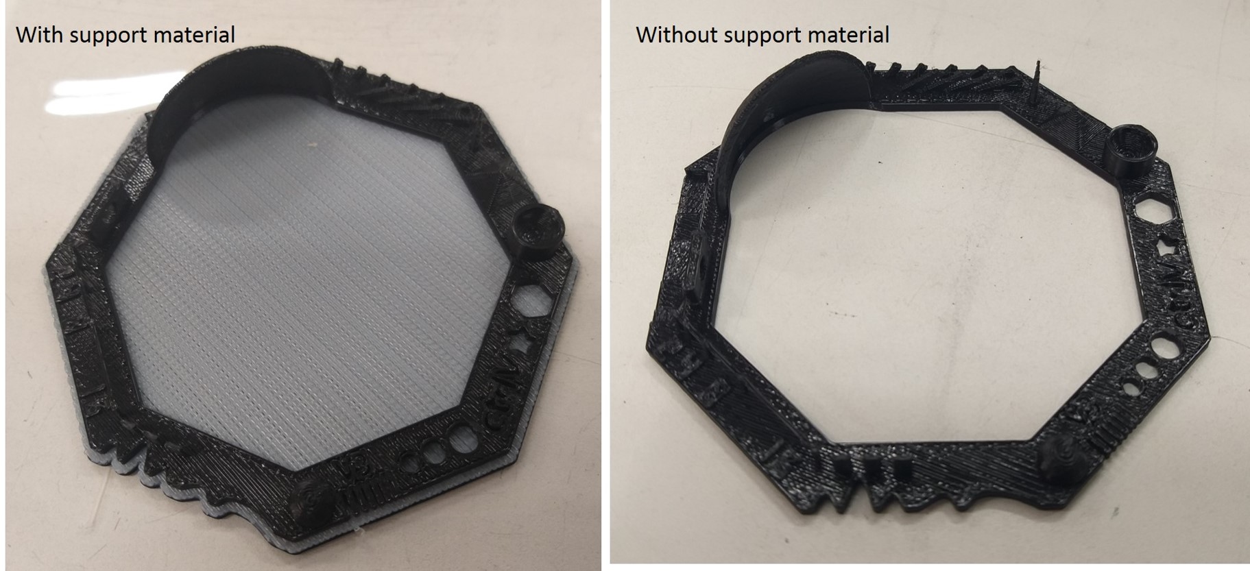
The support material is soluble forms. The printed structures carefully peeled off from the base material and allow to dissolve the support material in the NaOH solution tank in the fab lab. The most common defect in FDM is warping. This is happening during the extrusion and cooling process during solidification. The thermal shrinkage anisotropy leads to warping which affects the flat area, thin protruding and sharp corners.
We have also tried the same print design for other printers for characterising the features of the different printer.
-FormLabs printer
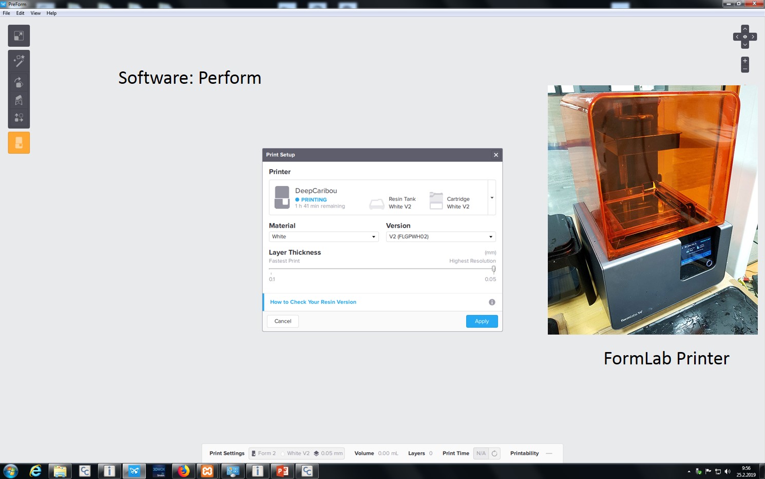
FormLab works with the technology called Stereolithography (SLA), Photopolymerization of resin to shape the output by solidifying the resin layer at a time. See the images of printer and software in the below figure.
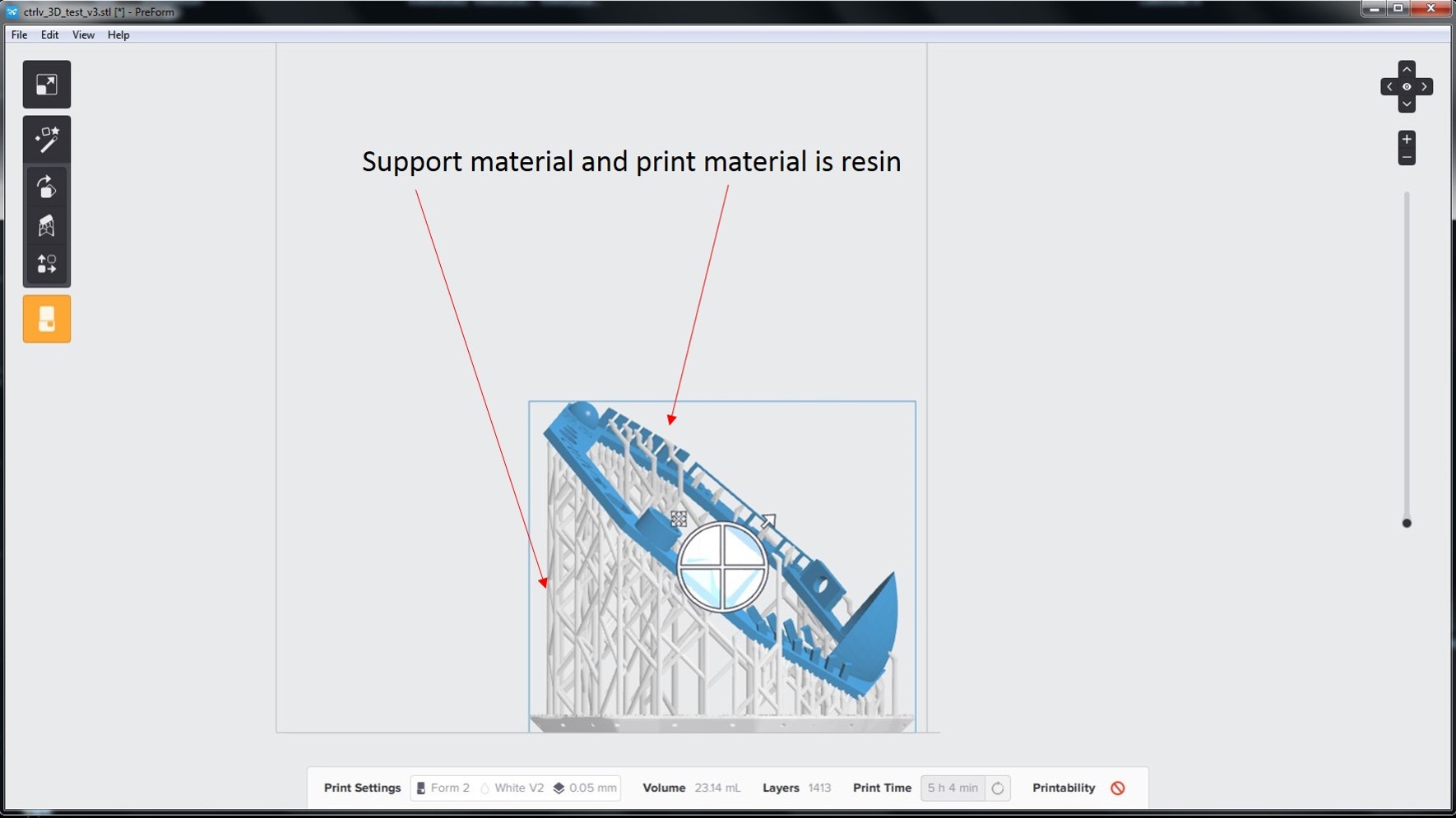
Total time taken for the printing is 5 hours and 4 minutes. In this printer both support material and material printed is resin. Final print attained after manually remove the support material. See the screenshot of design and support material below,
This printer also prints by the bottom-up approach; the total build size is up to 145x145x175 mm. Typical height attained is 25 to 100 microns. The material used is resin. It first builds the platform lower to the tank of resin. Due to the limitation of time we have not print the design.
-Sindoh 3D VOX printer
The software used for this printer is Sindoh 3DWOX. This printer working principle is fused filament fabrication of thermoplastic materials. Here, materials are pushed through an extruder. The extruder for this printer has a cold and hot end. The hot end consists of the heating chamber and nozzle. This printer nozzle diameter is in between 0.3 mm and 1 mm. Different type of nozzles and heating method are used depending upon the materials used. Maximum build size for this printer is 200 x 200 x 185 mm. See the figures below the picture of the printer and design file update.
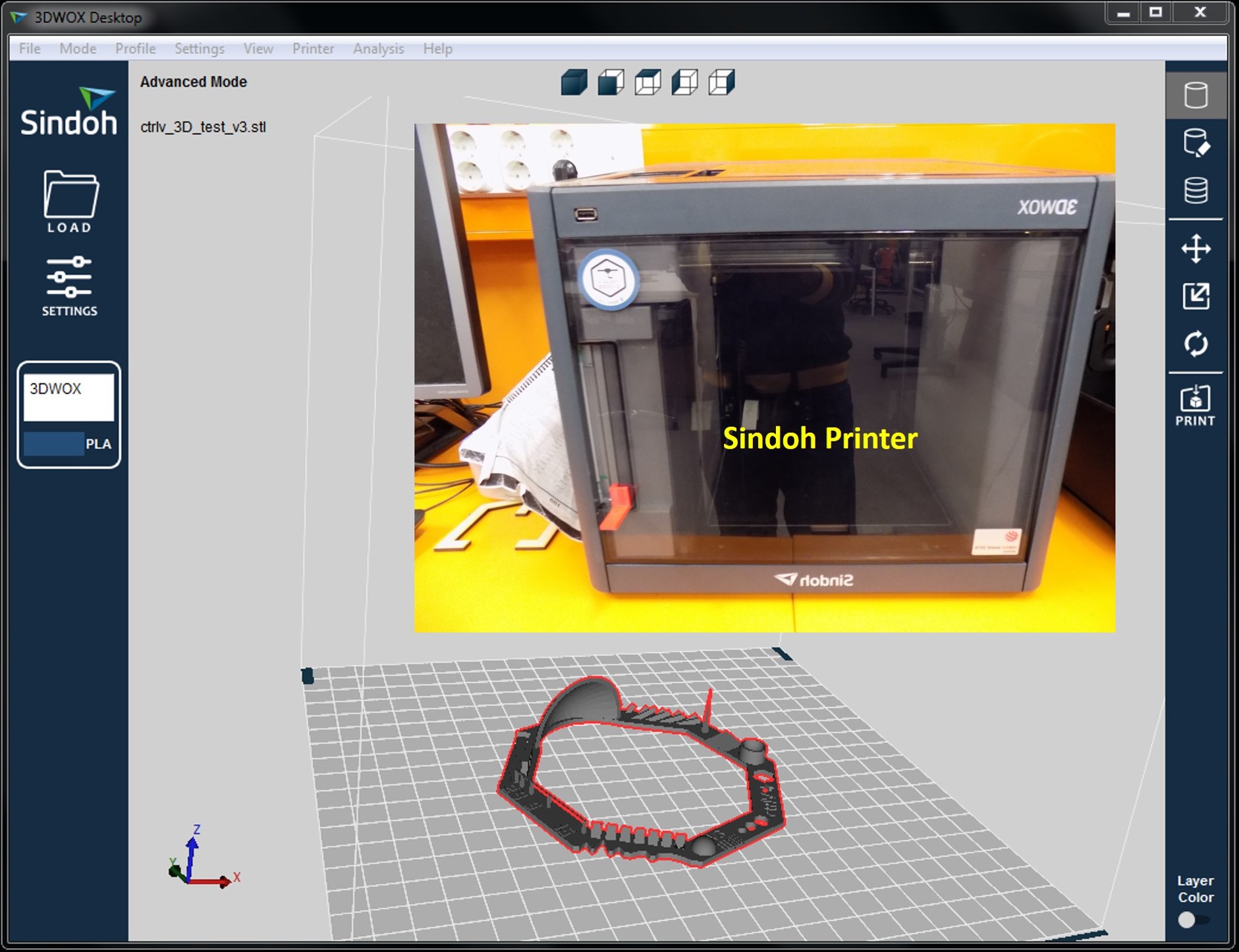
It is also seen from the above figure that the designed file is opened (click load file) in 3DWOX software for print. We can also change the position or orientation of the object by left side keys. If the position and orientation checked the file ready for print it. See a couple of screens screenshots for the setting of the design file.
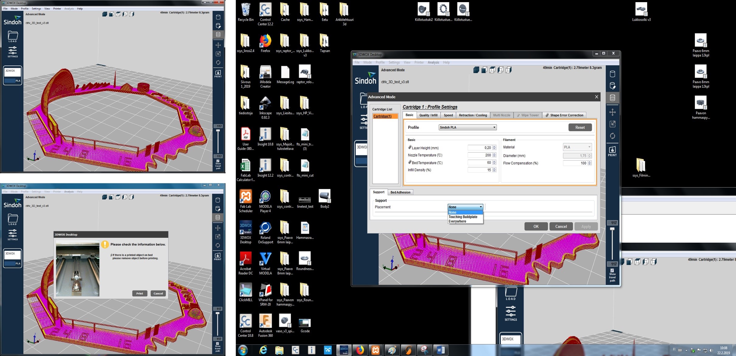
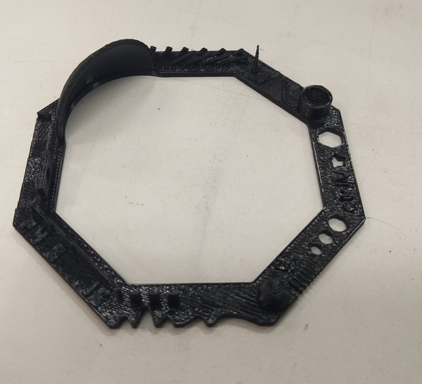
Printed design is shown below,
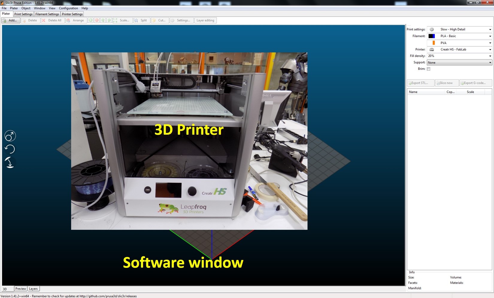
LeapFrong printer uses Slic3r software for controlling the print characteristics. The material used is PLA and support material is also the same due to the unavailability of PVA. This software is a background slicer, the path of the Slic3r - fortrus - open ‘Arkkitehtehtuuri 3D’ Folder - Sli3erPE - slic3r - (name of printer: creator HS)
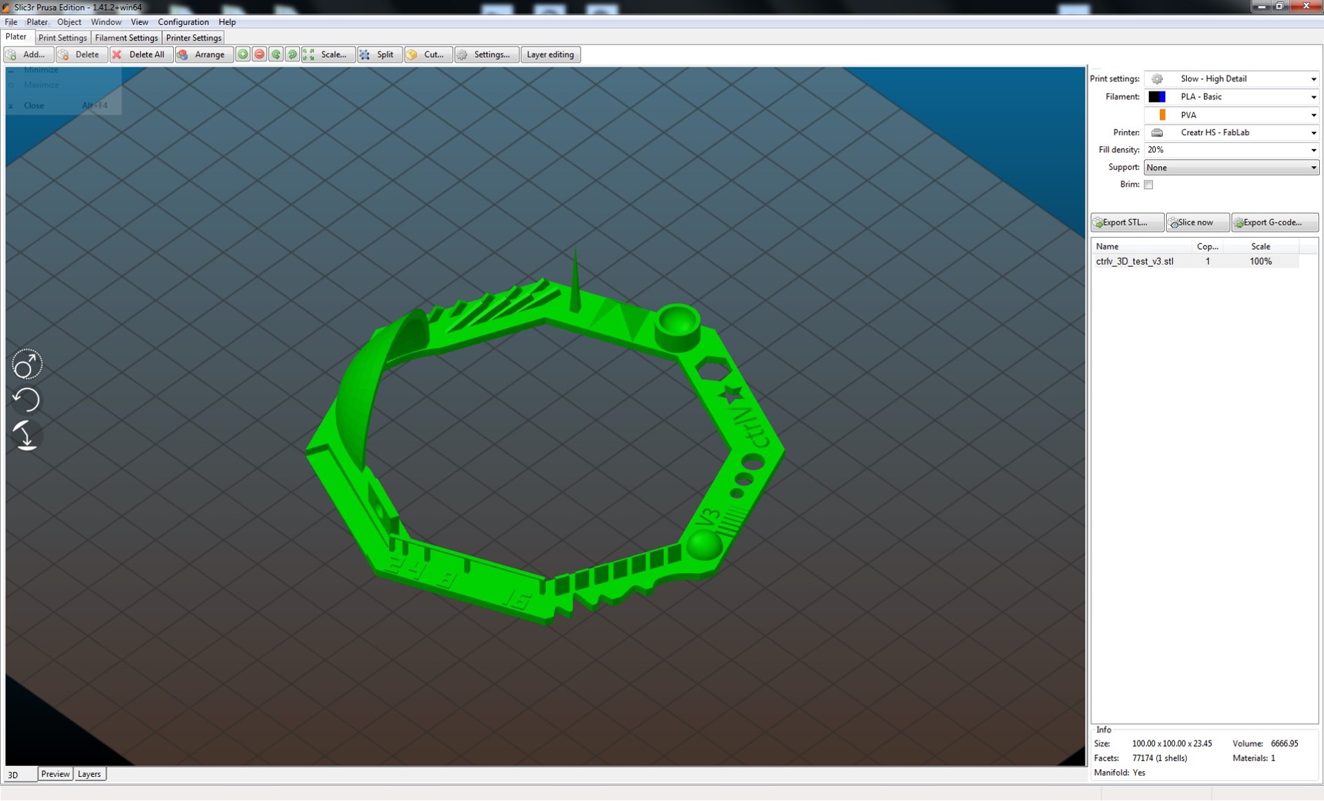
See the screenshot of design in Slic3r and image of the printer below,
Add design file to Sli3r-rescale if necessary-create Gcode for printing. Check the default print settings of material PLA and support material is PVA. See the screenshot below,
See the G code creation step and print process in the printer.
Our group member Sahan made a nice comparison table for more information about the various printers used. A comparison figure is shown below for more information.
The 3D printed design each area analyzed based on its design features, such as COMB, Small circle, Hexagon, Irregular, Star, Circle+rectangle, Dome, Inclined plane, Tower, Hollow Cylinder, Pyramid, Tower, Inclined plane and Tower surrounded. These mentioned areas of 3D structure using 3 printers such as Stratasys Fortus 380MC 3D, LeapFrog 3D and Sindoh 3D VOX. As an example from the figure, COMB part, printer 3 and printer 1 line are observed, but printer 2 no COM lines observed. Another part Tower, printer 1 with clean tower with shorter height, printer 2 great irregularities, printer 3 tower height with slight irregularities at the top. Similarly, all the geometries in the design are explained clearly in the figure. This is a good example of the comparison of 3 different 3D printers. These summaries are good for the final project 3D printing of various shapes in the consideration.
Individual work
3D design and 3D printing
My assignment is to design and 3D print a simple particle in a box model. I have used Autodesk Fusion 360 software for design the particle in a box model. I got this idea from the previous year documentation of [Jari] (http://fabacademy.org/2018/labs/fablaboulu/students/jari-uusitalo/week6.html). This is a good example of showing 3D printing for additive and subtractive manufacturing. This design cannot be made by any of the top-down approaches such as milling or lasering. By lasering or milling cannot create a free and well dimension particle inside it, hence 3D printing is unique technique for additive and subtractive manufacturing. Below explains the step by step documentation of my particle in a box design.
Step 1: Open fusion 360 and start to draw a square of 50x50 mm in origin point. See the screenshot below,
Step 2: Go to Create - Extrude 50 mm for 50x50x50 mm. See the screenshot below,
-Step 3: Select all cube edge for Modifiey-Chamfer with 1 mm
Step 4: Select full cube and Modifiey-Shell with 4 mm
-
Step 5: Select one face and Create 9 holes with dia of 10 mm and length of 50 mm and Select 18 circle belongs to each hole at 2 faces and Modifiey-Chamfer with 1mm
-
Step 6: Rest of the 2 faces is also creating a hole at centre with 10 mm dia and 50 mm length
-
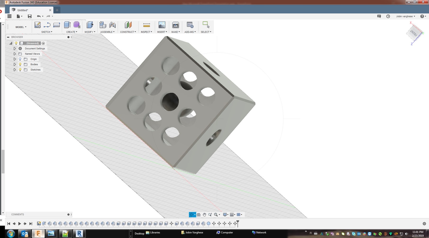
Step 7: Create a separate sphere of 20 mm diameter and move to the centre of the developed cube
-
See the screenshot of the final design for printing below
Step 8: Select all file and Make-3D print-it open another window as shown in the screenshot below,
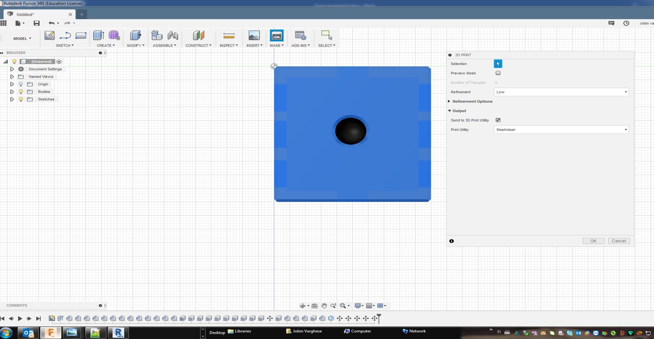
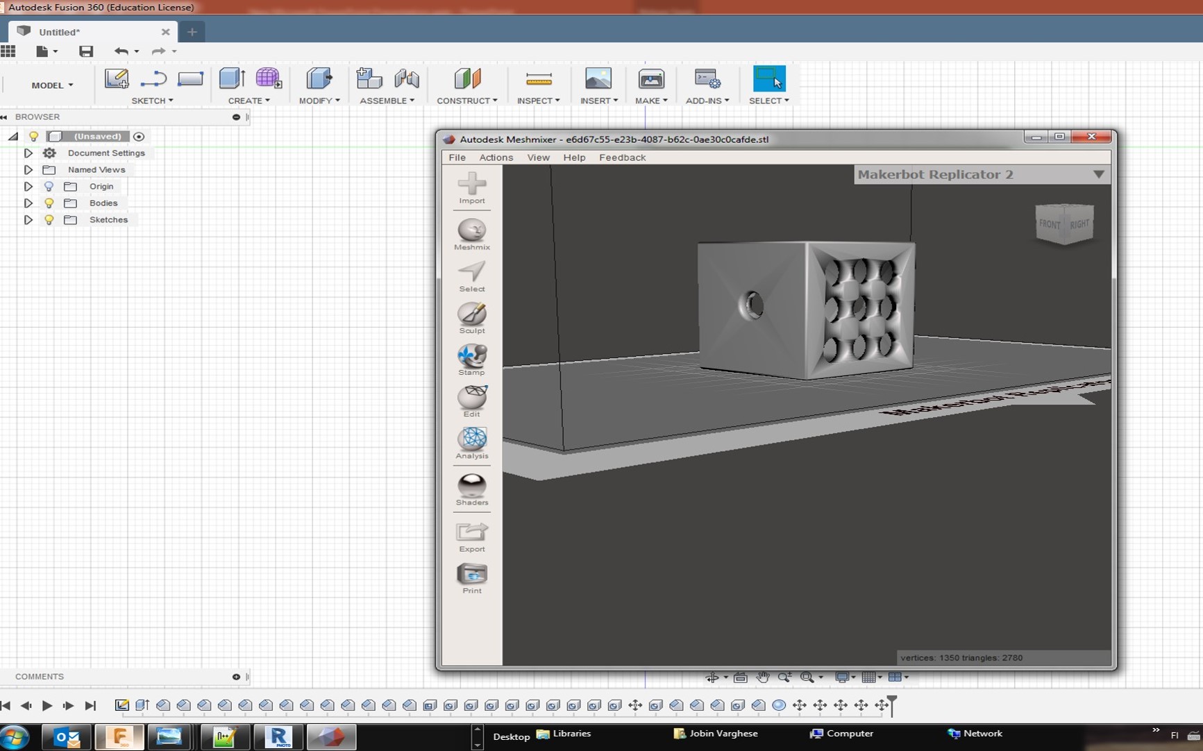
Step 9: Press OK to 3D print window which open mesh mixer and finally export as stl file format for printing. It is also possible to save as stl without mesh mixer. See the 3D design mesh mixer below screenshot.
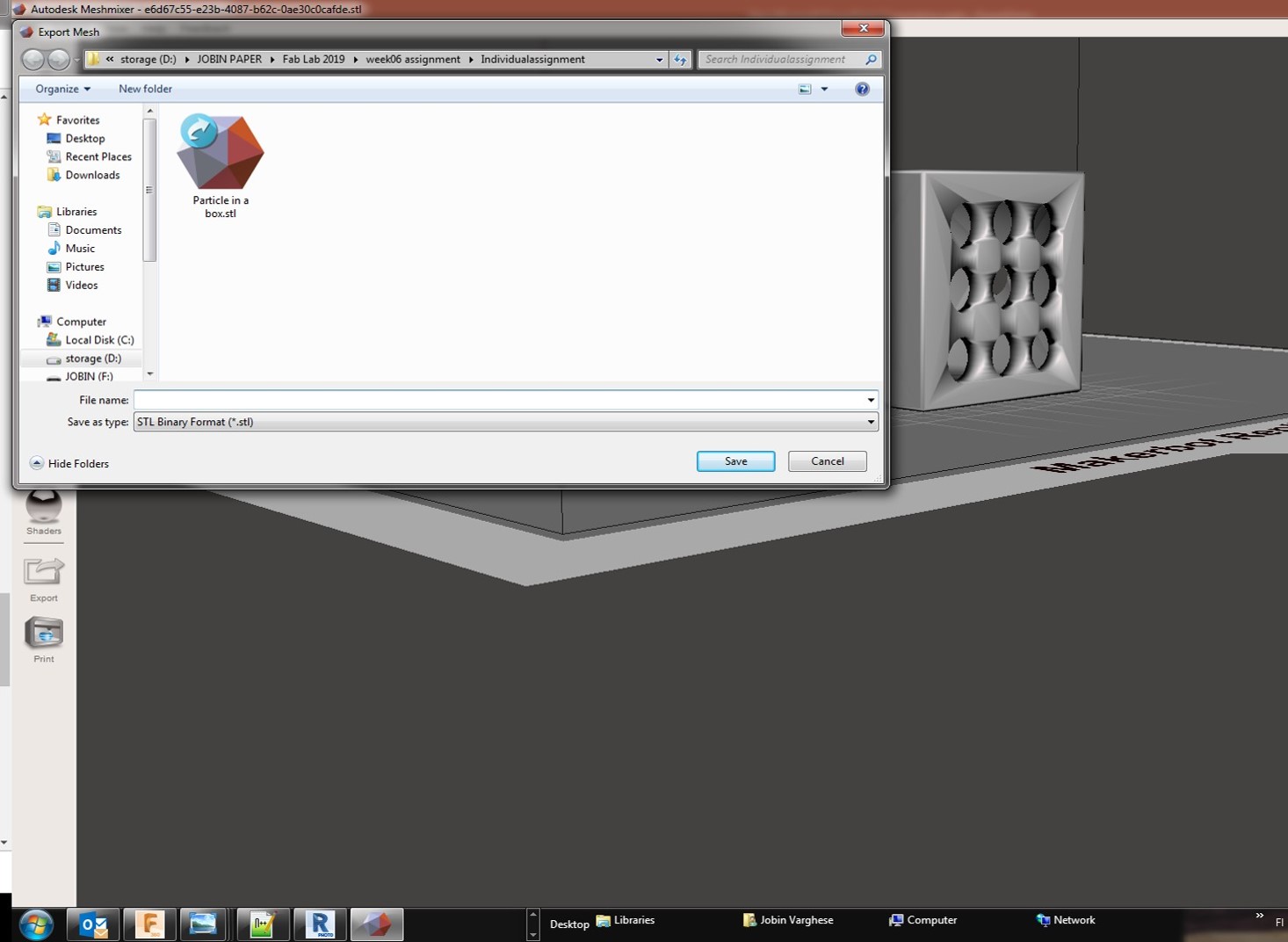
Finally, export as the particle in a box.stl file format for 3D printing. See the screenshot below,
Before printing, initially I place base material to the printer using thermal glows. I used Insight software used to assign print job to printer. See the screeshot below,

File open the stl file which I designed for my assignment which is particle in a box concept with additive and subtractive part. See the screenshot of design file in Insight software,
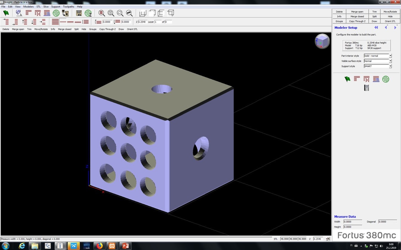
This file I have done 2 mistakes one is my internal solid sphear is not selected for stl file conversion. We cannot see the sphear in the design. Then, I go back to fusion 360 to save again the stl file for print. See the below screenshot for wrongly placed support materials. Then I changed design by rotation to use minimum support materials used.
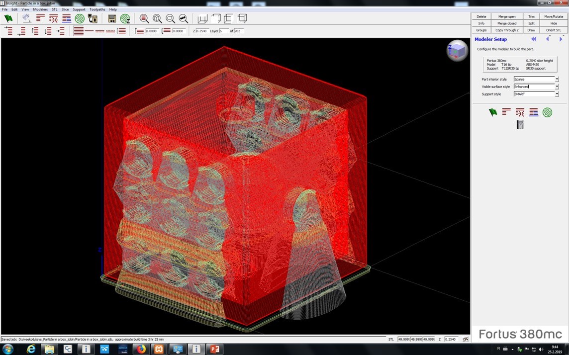
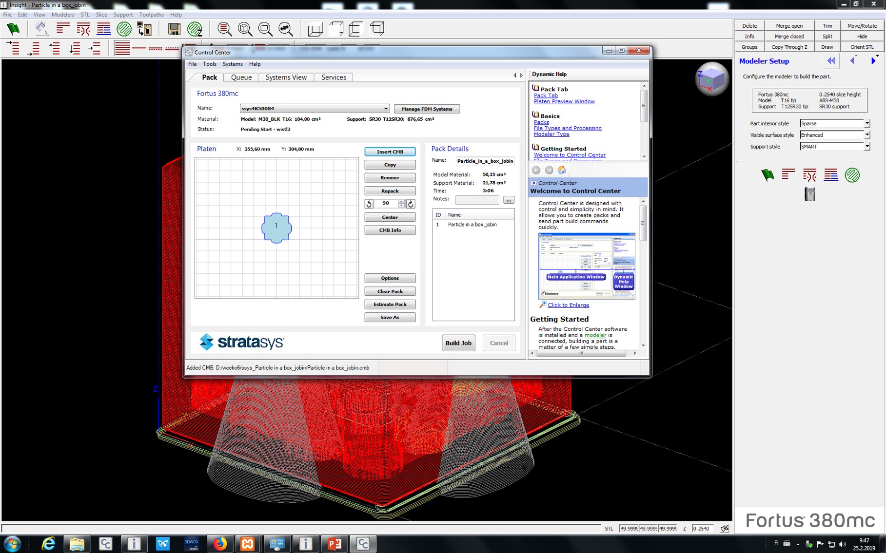
Then I selected configure the modeler build part, select part interior style-Spares, surface style is Enhanced and support style is SMART and then I followed default printing process by control centre and check the amount of materials used and build the job. See the screenshot below
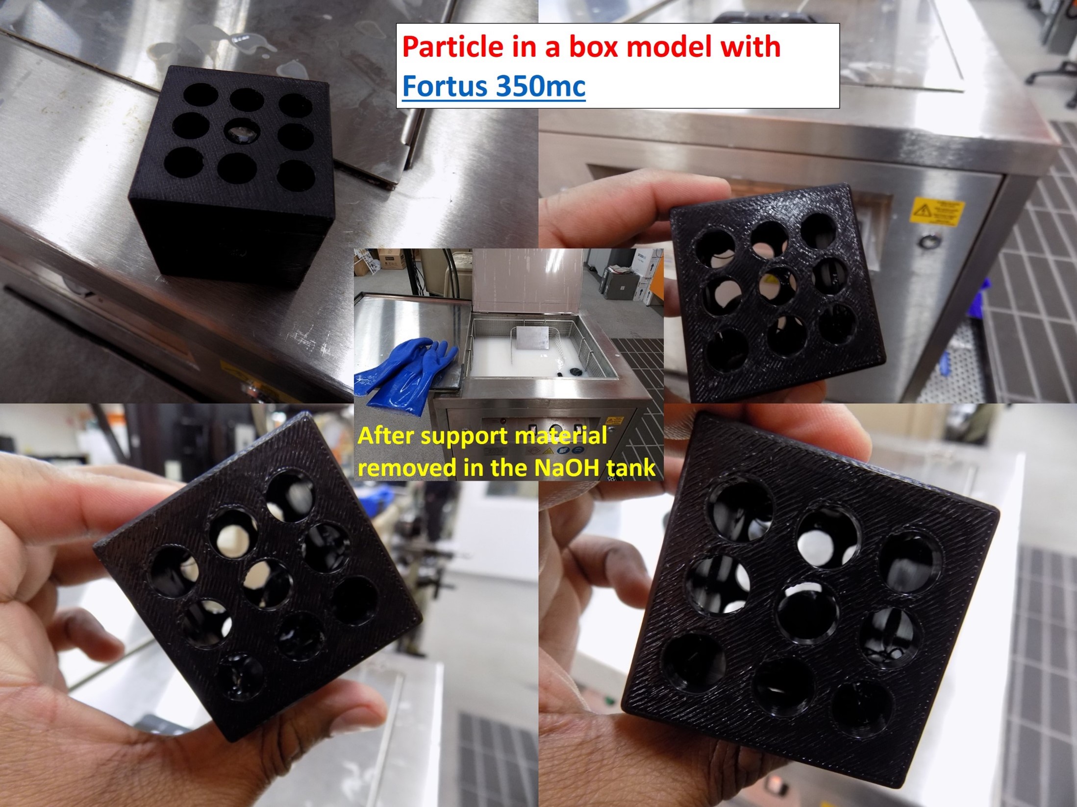
All the printing process already mentioned in the group work. The printed sample is kept it in NaOH solution for dissolving the support material. Base material is peeled by using sharp edge knife. See the below figure of my design prototype.
3D Scanning
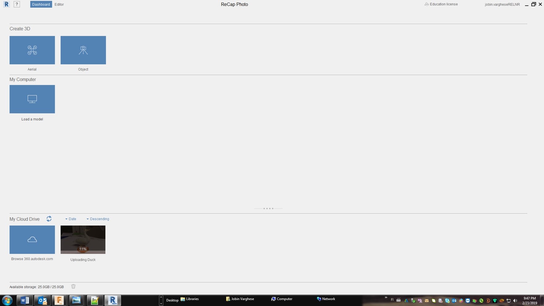
The second part of the assignment is to scan something and if the time permits print it. I used Autodesk ReCap version software used for scanner images. Unfortunately, the results were failed. I have taken a set of pictures (20-50) for creating the 3D images. A toy duck object is selected for the studies. See the screenshot from the ReCap below,
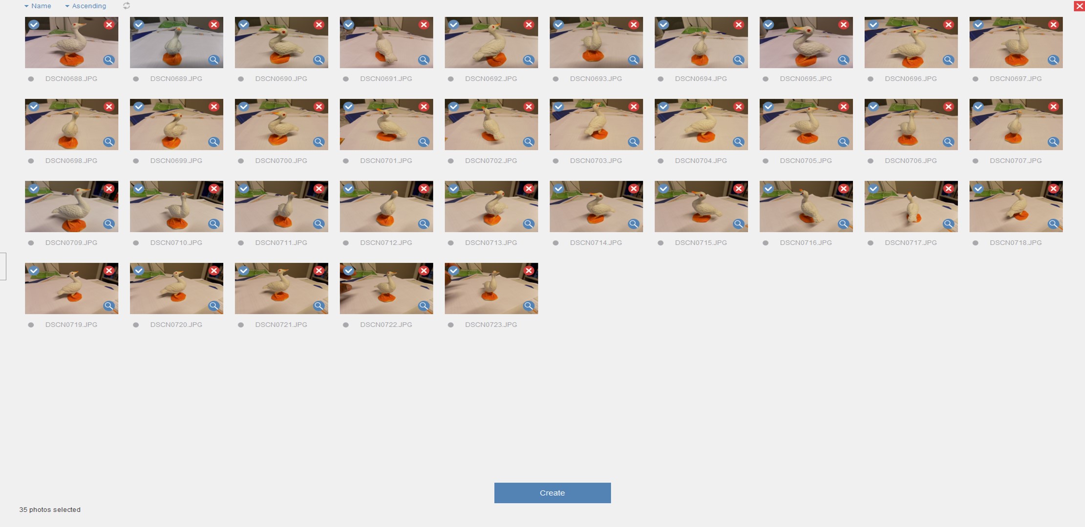
See the selected figures in the reCap
A wrong 3D object at the final result
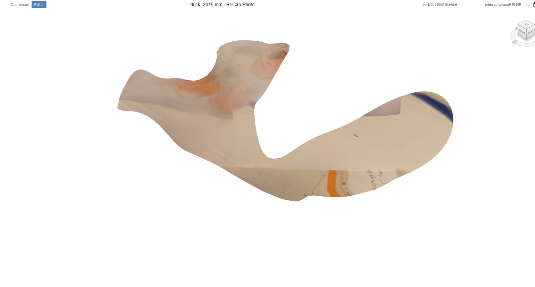
I observe that picture quality, light also the angle of rotation was also important for doing this work. I lose my patience with the camera.
Then I plan to do it with 3D scanning applications the same object using a smartphone application. Its interesting and understand the concept.
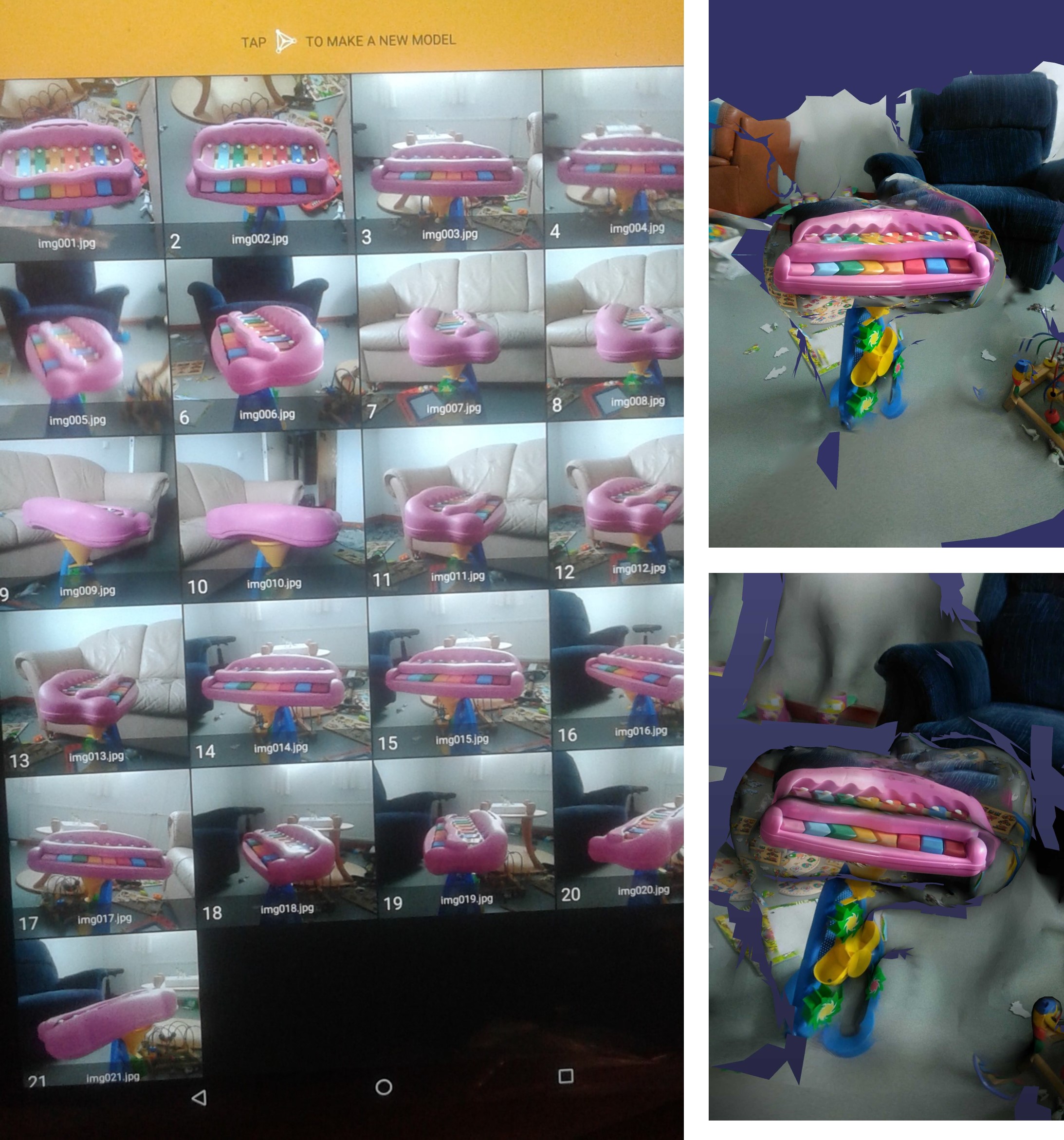
Then I, plan to do it with 3D scanning applications SCANN3D the same object using a smartphone application. It’s exciting and understands the concept. See the screenshot below for my objects created 3D image. SCANN3D is developed by SmartMobileVision and is only available for Android. One big advantage professional handheld 3D scanners and depth sensors have over most photogrammetry solutions is that they offer real time guidance during the capture phase. Specifically, they use real time fusion to show what parts of an object have been scanned so users know when all angles are covered. Single-camera photogrammetry usually relies on the experience of the person taking the photos to know when enough photos are taken for the algorithms to produce 360-degrees models. This requires estimating if every photo has enough overlap with others. Anyone can perform processing right after capturing but also start a new capture and process everything later. Projects are nicely organized in image sets which can also be renamed for extra convenience. It makes sense to process pictures with the basic setting first to see if the image set is good enough to be solved. You can export the 3D model as a mesh in .STL, .PLY or .OBJ formats directly from the app.
First one is a duck
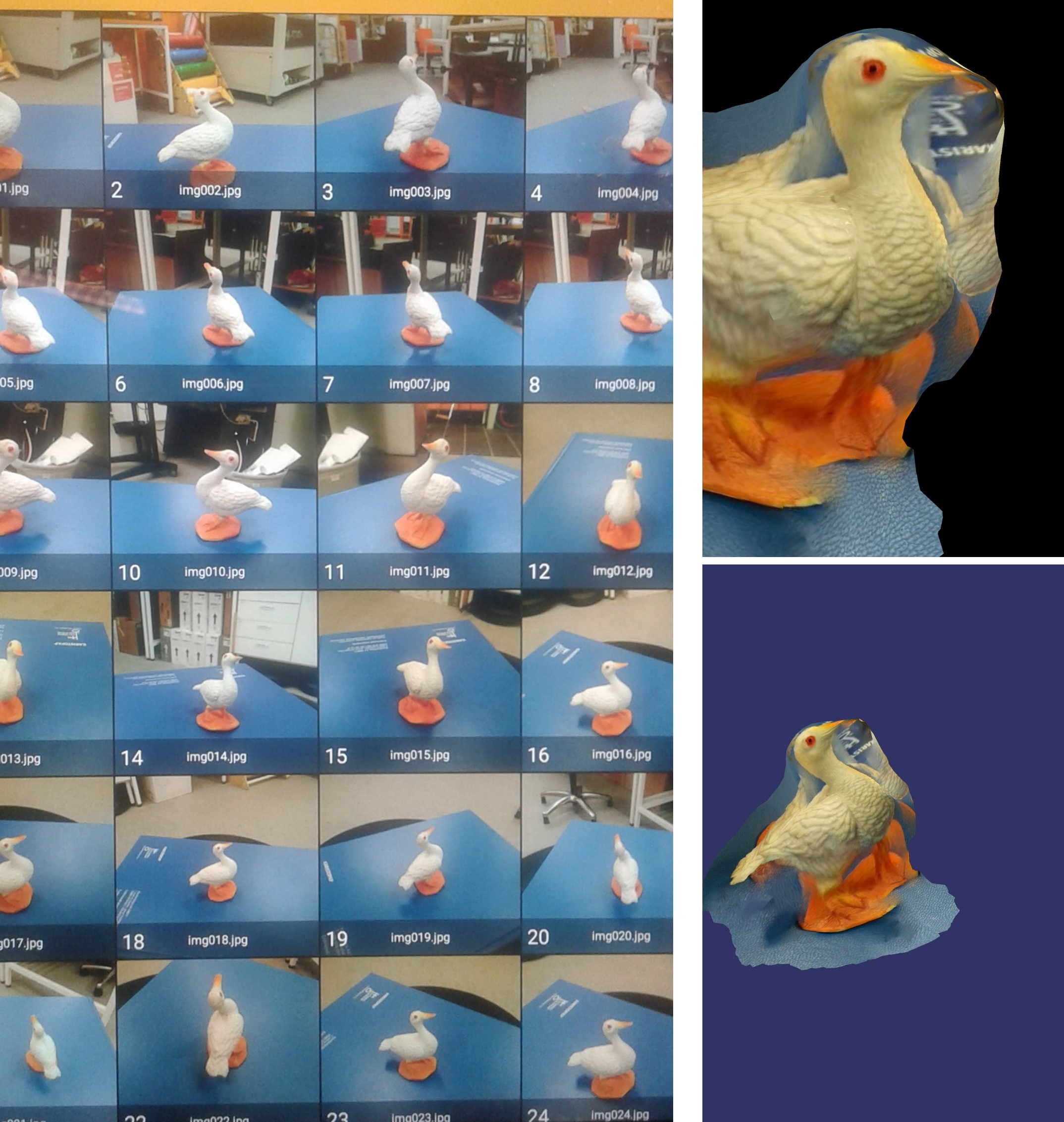
Second is Xylophone
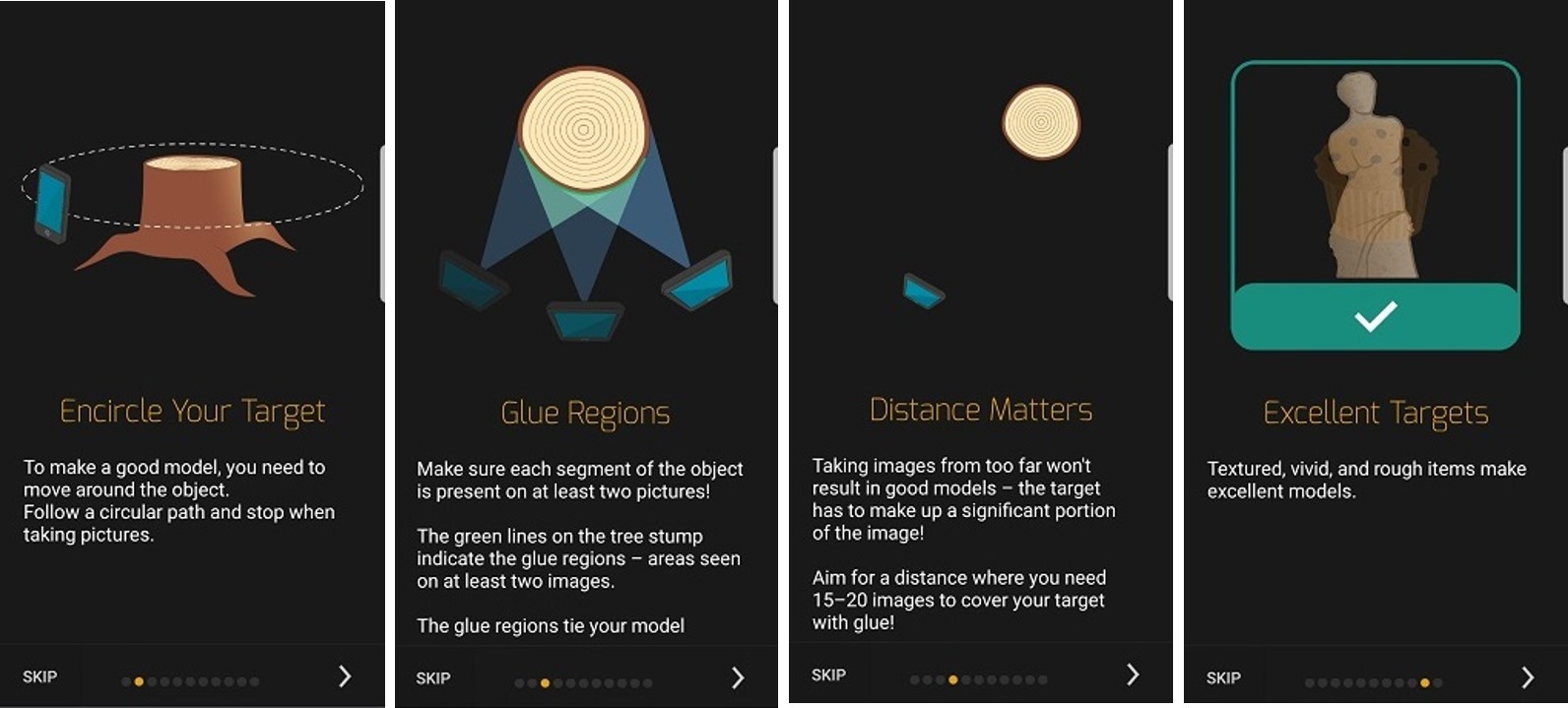
Some of the learning objective from the studies for a good model is taken the maximum picture by encircle your object, follow the circular path, make each segment of the object, far object picturing leads to wrong models shown in Recap model above, maximum number of pictures need for good 3D models, spotlights, hard shadows and uneven light leads to incomplete model, soft shadows results in good models, insufficient to move target object alone, need both target and camera by 2 sets of pictures for good models, Cannot use moving target, reflective or transparent or untextured object do not make good models, and textured, vivid and rough objects make good 3D models. I also found some useful information for scanning the object. i have done it for several time, but still not suceed with the 3D scanning of the object. See some of the tips for the 3D scanning that is shown below figure,
Design files
Summary
This week group assignment and individual assigntment learn many new things such as 3D design using Fusion 360, characterise the various printer used for 3D printing. The factors affecting 3D printing and limitation of 3D printing. Among the various printer, I obseved that FormLab printer is good for high resolution 3D printing which use stereolithographic process by bottom up approach. The main disadvantages for this printer is to use same material for support and printing design which limits the functionalities some extent. 3D scanning by imaging the object and create the 3D models. This part, first my attempt was failed. But 3DSCANN application really help to understand the concept clearly. Still not succed with 3D scanning printable 3D objects models.