6. 3D Scanning and printing
This week we had an overview on 3d printing and some 3d scanning techniques. This week assignement is to print calibration patterns and define the 3d printer, to design and print a 3d model that can’t be made subtractively, and to scan a 3d model.
Callibration pattern
I choose to print this callibration pattern : STL file . It is made by Autodesk with a kickstarter campaign : https://github.com/kickstarter/kickstarter-autodesk-3d/tree/master/FDM-protocol
I have some old habits. I am used to visualise the STL file in MeshLab .
I use Cura 3.6 from Ultimaker to produce the Gcode for an Ultimaker 3 extended.
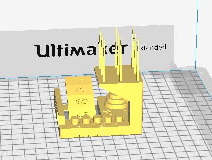
The Ultimaker 3 extended was equiped with a 0.4 nozzel and was printing PLA from ColorFabb . It’s an FDM 3D printer in cartesian mode. It has 2 extruder, a heating bed, an automatic callibration of the bed leveling and many other easy features.
Then I follow the tutorial on https://github.com/kickstarter/kickstarter-autodesk-3d/tree/master/FDM-protocol
As indicated in the tutorial, I’ve used all the default parameters / - layer height 0.1 mm - infill 20 % with “grid pattern” - wall thickness & top/bottom 0.8 mm - print speed 60 mm / s - a brim adhesion - the extruder temperature is 210°C - the bed temperature is 60°C
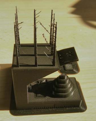
printing time : 7h03 for an amount of 4.59 m of filament
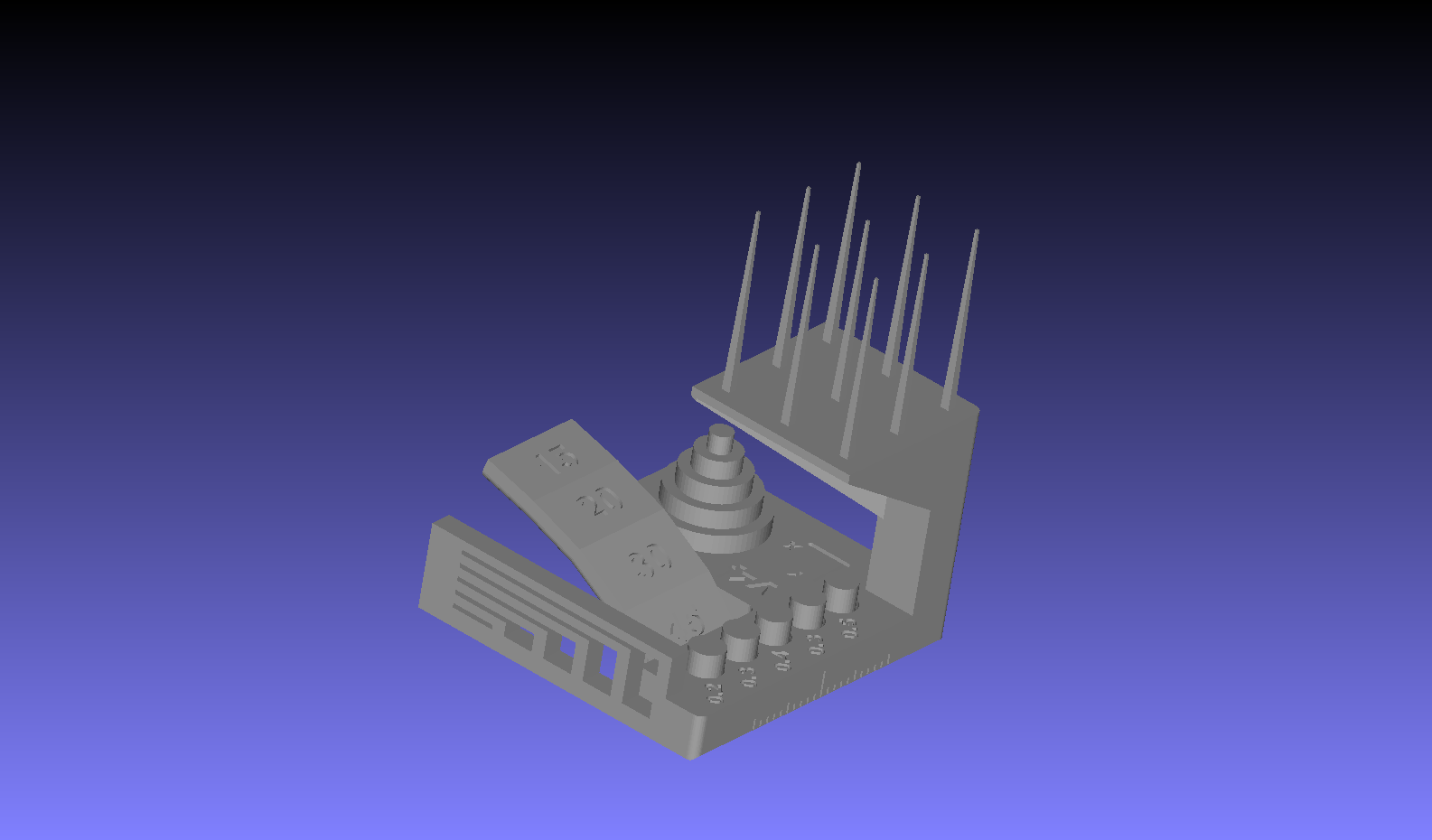
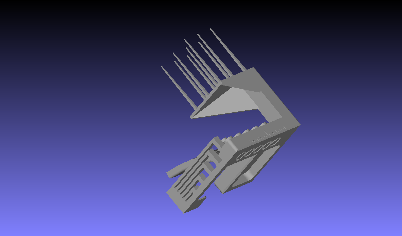
Some pictures of the result. I had only my phone at that time to take some pictures. It is not the best solution…
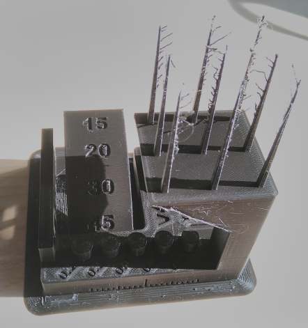
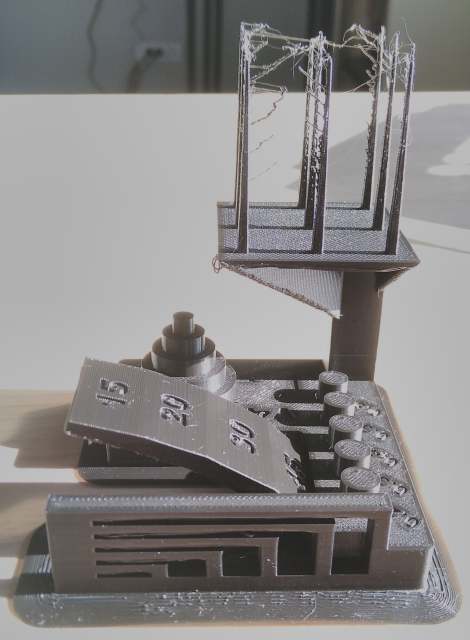
All those features tells a lot on the horizontal brige size, hole size, minimum wall, minimum pin diameter, overhang angle, size tolerances…
I recommand the book The 3D Printing Handbook: Technologies, design and applications Hardcover, 2017, by Ben Redwood, Filemon Schöffer, Brian Garret https://www.3dhubs.com/3d-printing-handbook/ too explore in details all those parameters .
You have to deeply understand how a 3D FDM printer works to optimise a 3D print. And it is impossible to predict all the glitch that will hapen, with experience, you can predict and avoid most of the glitches. But only by printing the same object again and agian, you can optimise each parameter. By building a 3d printer, you understand more, and by using differents 3D printer model, your understanding go each time further.
As descrived above, the callibration pattern MUST be printed with the default parameter to compare the performance of differents 3D printer, that’s the goal of a benchmark! It would have been a different idea to print an object with the best possible parameter to obtain the best visual result, and another one to have the best structural resistance, …
To describe one possible source of the “hairy” effect on the 3D test printing , the amount of plastic pushed by the extruder motor is melt by heating. When the motor stops, no more plastic is pushed inside the heating system. But the plastic at the end of the nozzel is still melt. The amount of melted plastic really extruded is difficult to predict. In the geomerty of the top part of the 3D printing, they are 9 pike in the shape of a cone. When the printer go from the bottom of those pike to the top of the pike, their is a small amount of plastic to extrude then the printer stop the extrusion, the head as to move to the next part to print. As explained before, it can’t stop instantly to print, the hairy structure come from that small amount of plastic that was melted and then displace to the next printed part. As you come from the bottom to top part, the amount of extrusion is reduced. So the head as to extrude at each layer less and less, stop the extrusion, and displace the head to the next pike. The result gives this effect geometry effect of hairy structure.
3D CAD
Goal : design and print a 3d model that can’t be made subtractively.
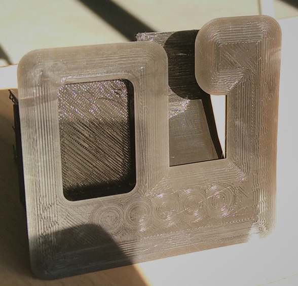
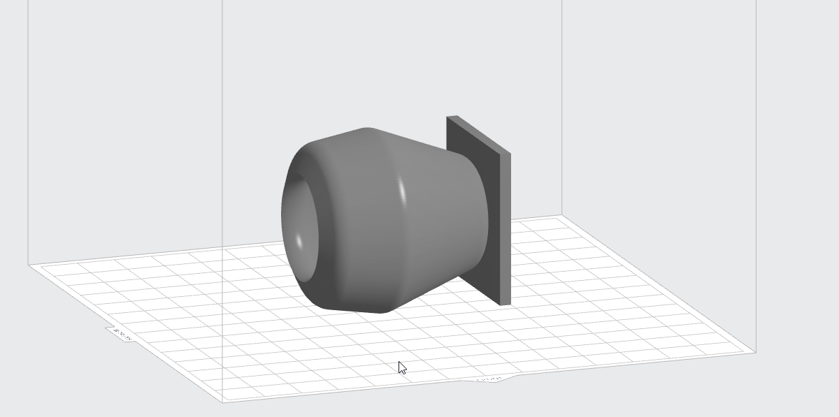
I design a cube. Then I design a sketch and a rotational axis
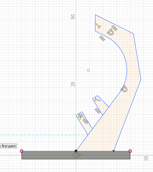
And make a rotational revolution. I apply some fillet on most of the edges.
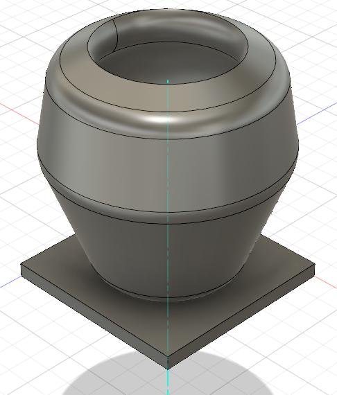
This design can’t be made in one piece with traditional CNC machining. The drill can’t access several parts inside.
I plan first to print this design on a FDM 3d printer but for pratical reason I had to use an SLA printer. For the Stereolitography priniting technology I should have design escape holes so the resin could move all around especially in the cavities. But the printing result does not seems to have suffer from this missing feature.
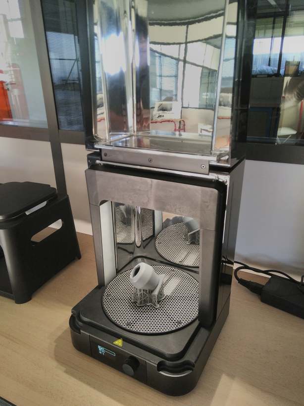
3D print - Stereolitography
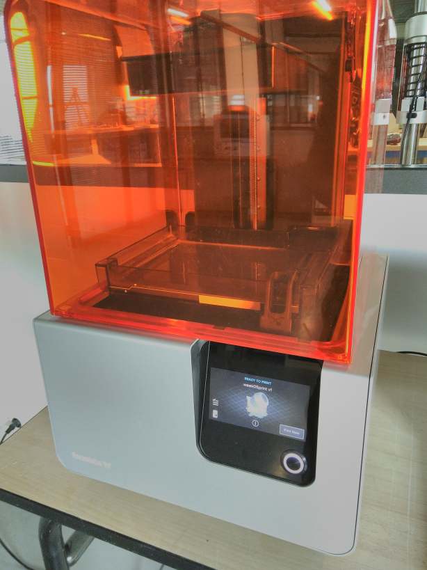
I launch PreForm, the software for the Formlabs printer. FormLabs has a wide variety of resins to print with .
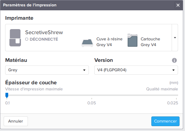
I use a Form2 3d printer with a Grey resin V4. Resin specifications
I select a layer height of 0.1mm . It’s less time consuming and is extremly accurate .
I import the .stl file
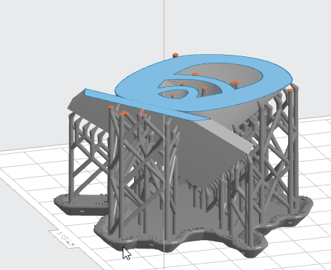
I click on the magic tool
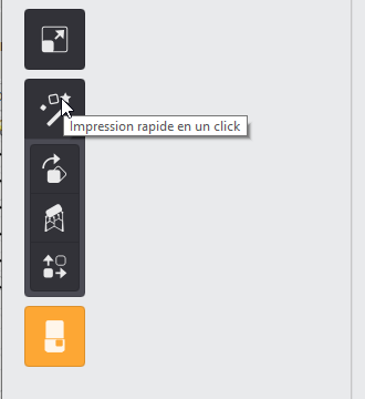
It rotates your object following a lot of rules (the resin should be able to move freely between each layer). Then it generates support following some other rules.
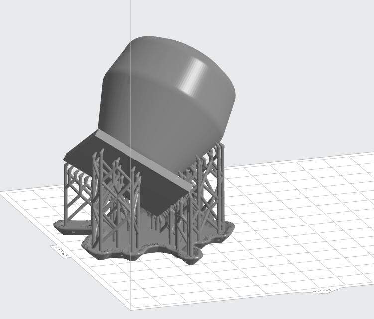
It’ll take more than 4 hours to print .

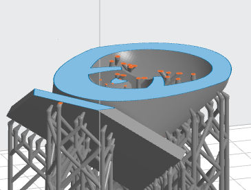
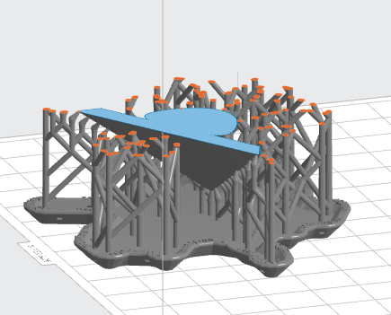
It’s always a good idea to move the slider to see all the layer
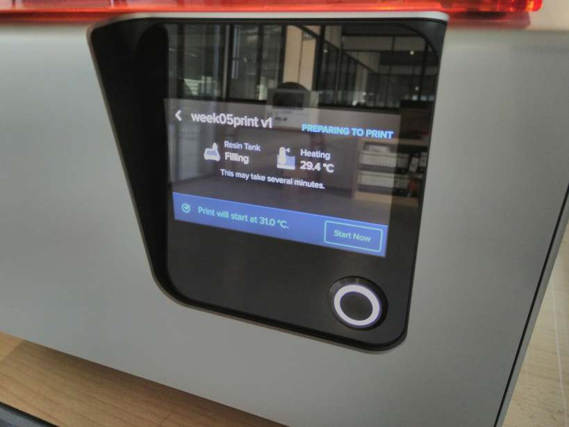
Then I launch the print. The file is transfered. You have several confirmation messages.
The print heat the resin to about 31°C. Then the print start.
The Resin is moved with a slider then the plate plunge into the tank that contain the resin . The laser placed under the tank make a pass and solidify the resin. Then another layer starts, the plate goes up again another slide to move the resin. And so on for all the layers.
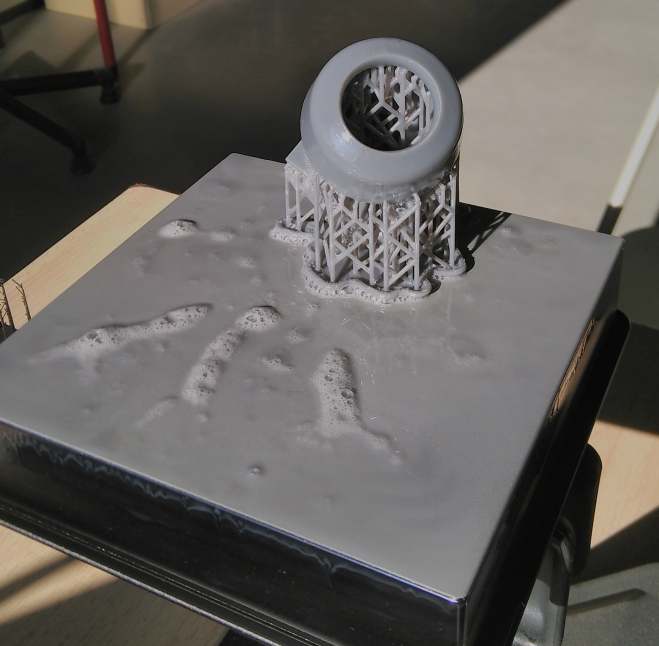
I have to cured the model, some uncured resign stick to the printed part.
You have to use glothes to manipulate the object, the sticking Resin should be disposed in a special way.
Stereolithography post processing
The FormLabs Wash is a device that plunge the object in IPA and agitate the liquid so the IPA can access all the geometry.
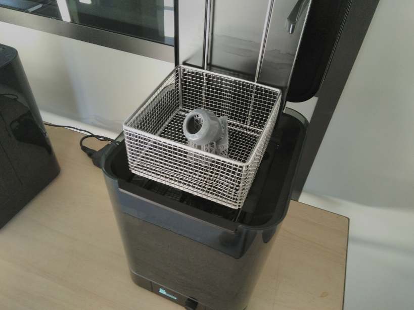
This action is done during 20 minutes. After that the object is cleaner .
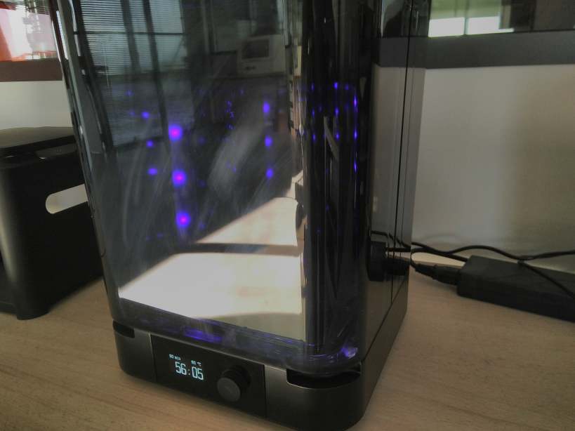
Then I place the object in the FormLabs Cure
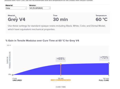
I choose the correct parameters for the grey resin v4 : 60 minutes at 60 degrees, the information is displayed on this webpage.
The device heat up to 60°C then it insolate with UV for 60 minutes.
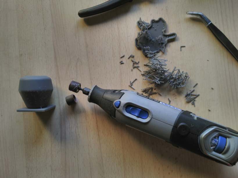
Then I removed the support
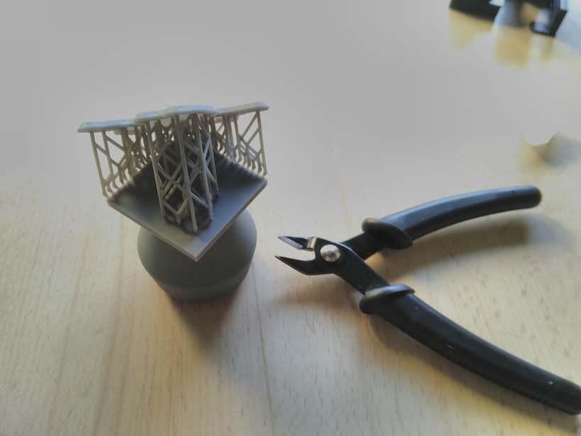
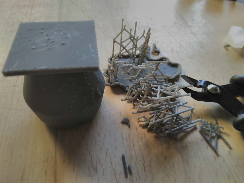
If you don’t want to see the small connections point, you can sand it.
3D Scan
I decided to scan the design I made during another week assignement . The scanner is a Shinning Einscan+ with the rotational table. It’s a scanner working on the principle of structured light.
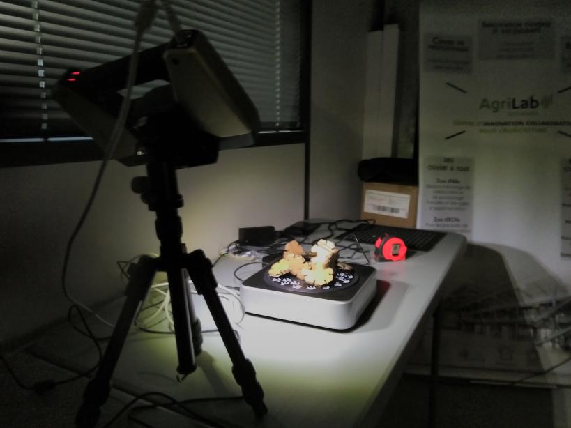
The object on the truntable with position patterns.
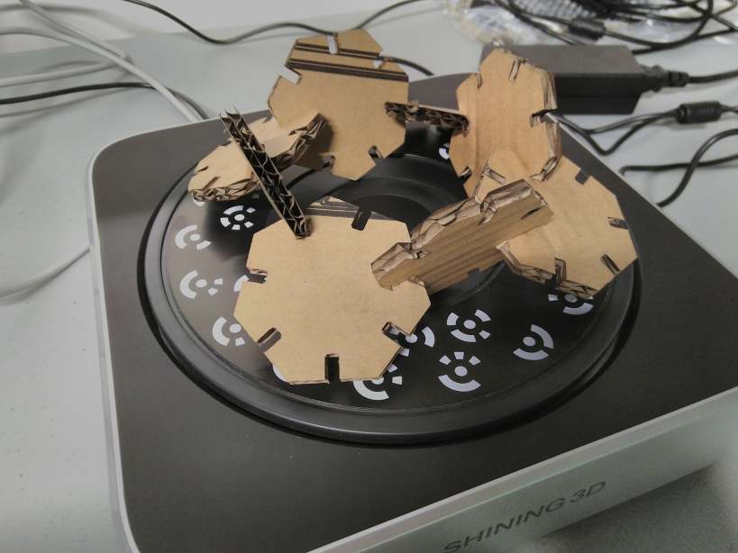
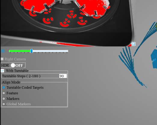
The software with the scanner does not give a lot of parameters. I just select that I scan with the turntable. Then you have access to a slider to adjust some kind of luminosity parameter and you can select the number of steps that the turntable will do to make a rotation of 360°. I select 90 steps and adjust a bit the slider.
The process take a certain time.
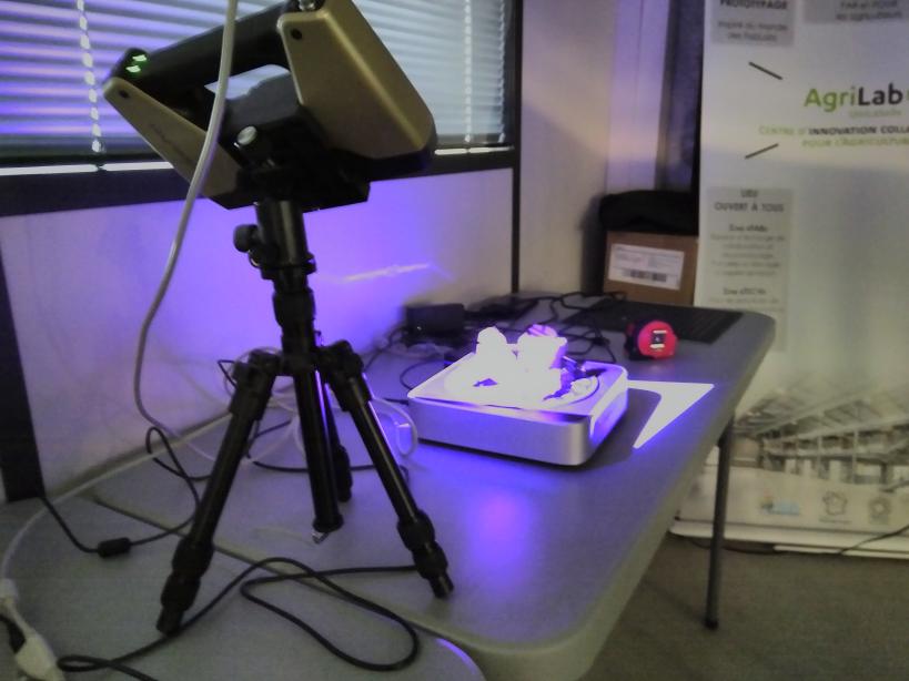
The projector project differents grids pattern on the object and 2 cameras films the deformation of the grid. It’s the process called structured light , you will find more information on https://en.wikipedia.org/wiki/Structured-light_3D_scanner .
At the end you get a visualisation of the 3d model.
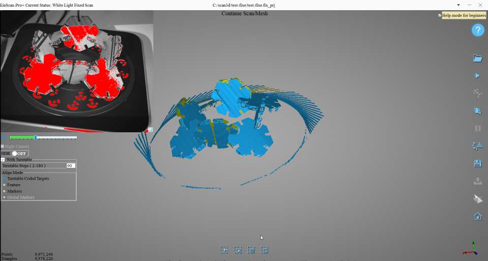
You can see the glitches. It has scanned the border of the turntable and rotate them at each steps…
An easy to use tool, allow you to remove the parts that you don’t want.

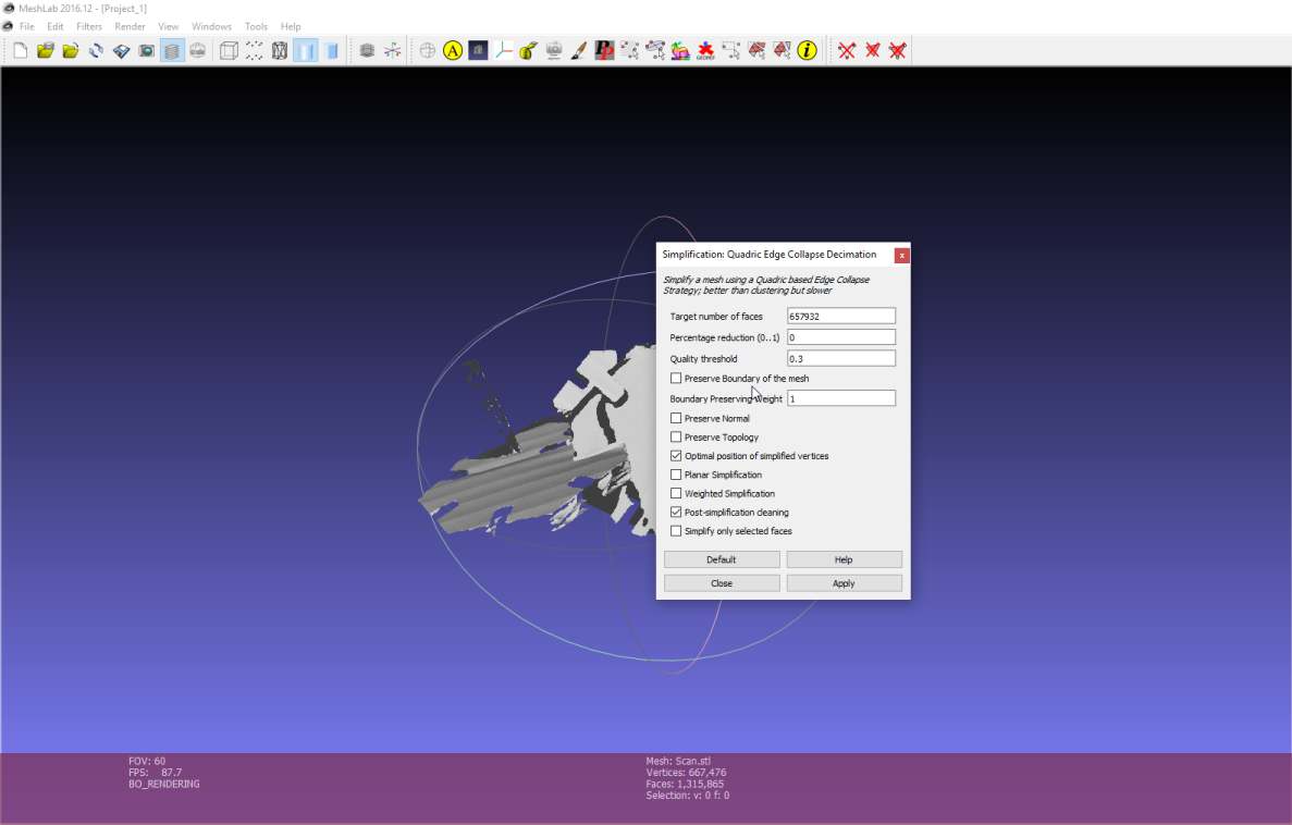
The last step is to convert your model to a mesh and export it in an stl or obj format. The software can directly do a watertigh object, but that’s a bad idea for this model. You can also “simplify” the model, It will reduce the amount of triangles in the final file.
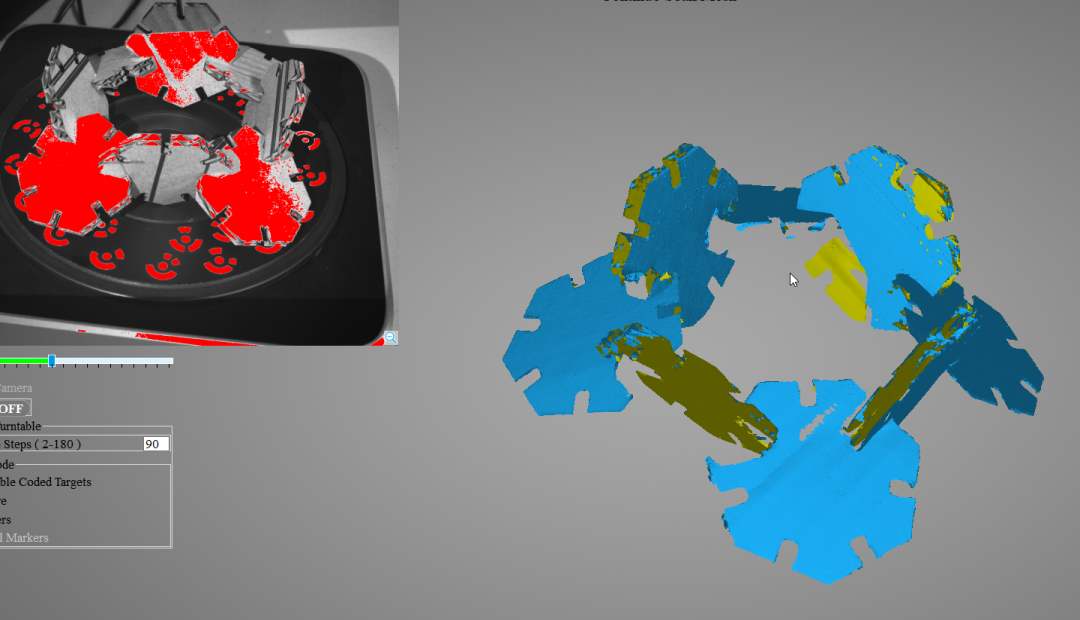
You can see some texture details of the cardboard on the scan model.

To place a file on this page, I’ve applied a reduction of the number of triangles. I use meshlab and the filter Quadratic Edge Collapse Decimation From 657932 to 30000 then I compress it to a rar file to about 700koctet.
3D Scanner, personnal opinion
This scanner doesn’t like black and grey colors and reflective materials. If you don’t use the turntable, you need to stick pattern everywhere…
I’ve tested some 3D scanners and I’ve nether had been happy about them. I prefer photogrammetry. It can give high resolution files.
But this week I did not have access to a good reflex camera with my 50mm fixed lens …
Their is always a huge work after the scanning process to remove glitches and to fill holes in a correct way.
For machining, I’ll advise to avoid the idea of a 3D scanner unless you had a really expensive one (50k€) and that you have a lot of time in fixing your model.
Files
- callibration pattern STL : STL file
- 3D cam files : week05printv1.f3d fusion file
- The scan reduced to 30000 faces in STL format: Scan_reduced.rar , size 708ko and a zip compression : Scan_reduced.zip , size 882ko