Fabacademy2020
Introduction
In computing, an output device is a piece of computer hardware equipment that uses received data and commands from an information processing system in order to perform a task (wiki).In our daily life we use somany output devivces, take a look at our computer speaker is output device ,Monitor is a output device (if it has a touch interface then input device too).In this week we are going to make a output device and i want to build something which can be usefull for my final project.
I decided to use RGB led because it plays an important role in final project. It would be important to understand how to control an led.
Basics of RGB Led
An RGB LED is a combination of 3 LEDs in just one package:
With an RGB LED you can, of course, produce red, green, and blue light, and by configuring the intensity of each LED, you can produce other colors as well. For example, to produce purely blue light, you’d set the blue LED to the highest intensity and the green and red LEDs to the lowest intensity. For a white light, you’d set all three LEDs to the highest intensity.
To produce other colors, you can combine the three colors in different intensities. To adjust the intensity of each LED you can use a PWM signal. Because the LEDs are very close to each other, our eyes see the result of the combination of colors, rather than the three colors individually. To have an idea on how to combine the colors, take a look at the following chart. This is the simplest color mixing chart, but gives you an idea how it works and how to produce different colors.
There are two kinds of RGB LEDs: common anode LED and common cathode LED. The figure below illustrates a common anode and a common cathode LED.
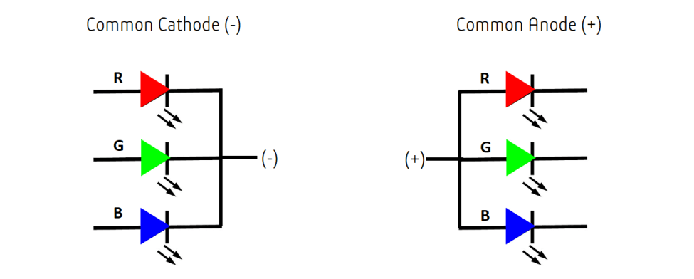
So, to distinguish between common cathode and common anode RGB LEDs:
Group Assignment
The group assignement for this week is explained in detail in the group page. To access the group page click here.
Board designing
For desgning the board i refered boards from previous years. And had an idea of which components are necessary. First i arranged the components in the schematic since i didnt use a ftdi pin i added a pinheader to use for I2C communication in the networking week. I am getting used to board desgning and slowly understanding how to make a board design fast.
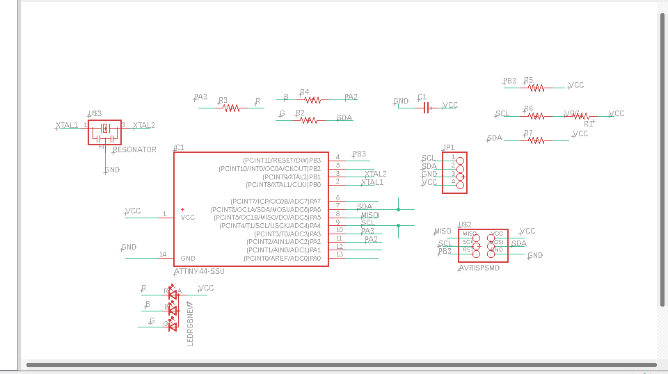
I am getting used to designing board in eagle and this circuit had more connections than previous board mainly due to number of extra resistors for LED.Its always better to arrange the components in order.
When the circuit becomes more complicated autorouting can only finish 60-70 percent of the route. rest should be done manually.
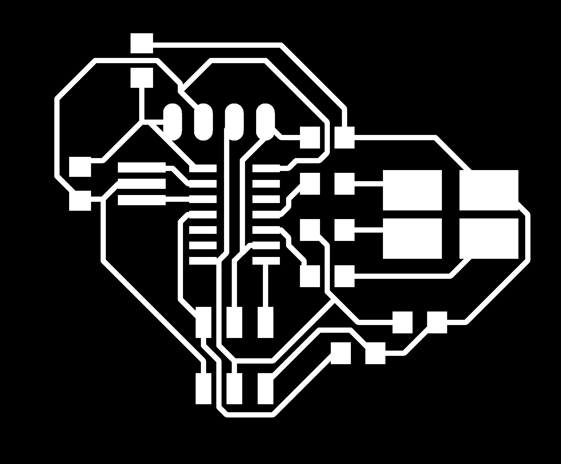


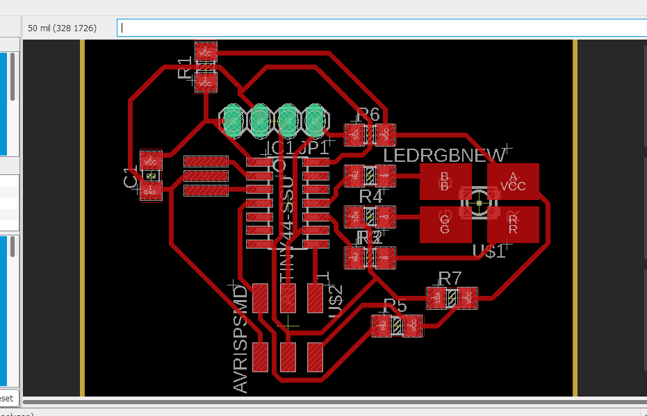
THe design files for milling.
Board fabrication
As usual the after designing next step is to collect all the components from inventory. Its always good to have a list of componets before hand.
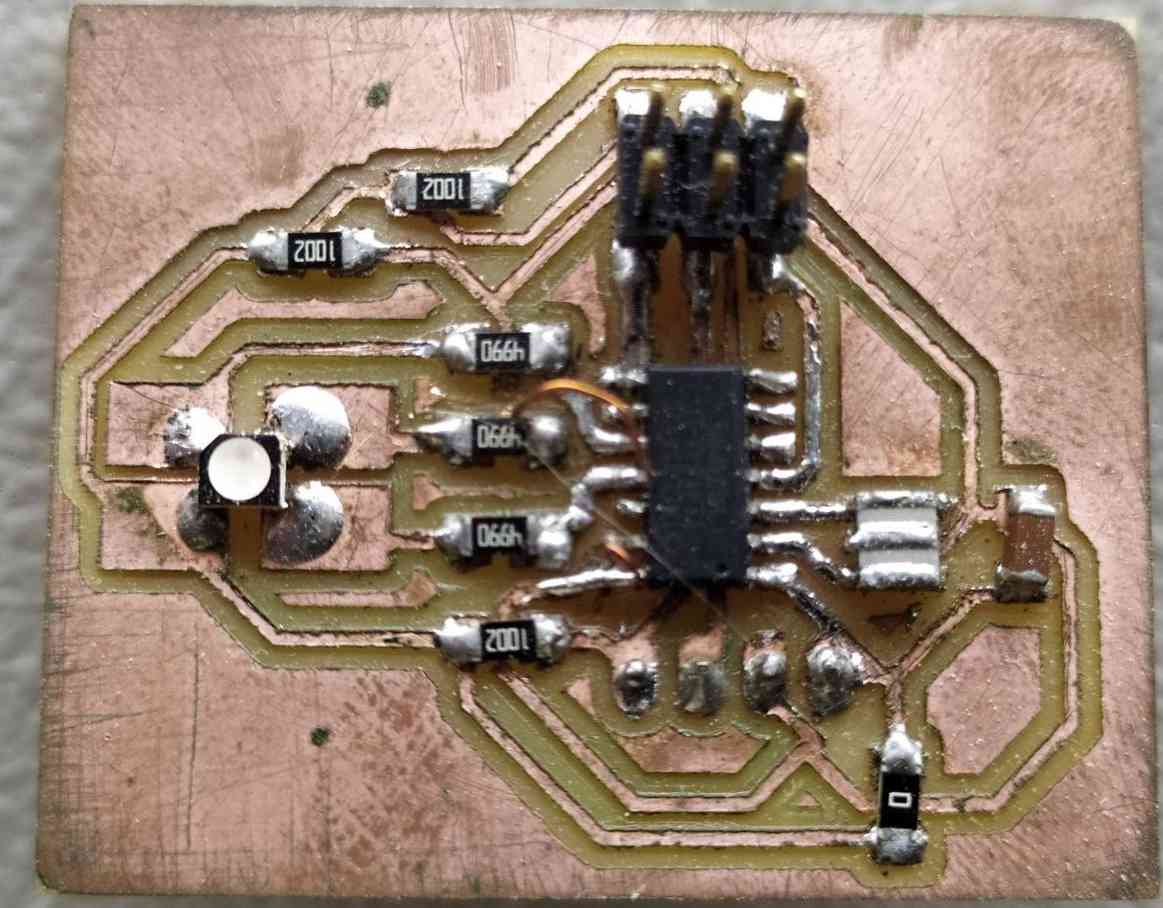
Components used.
| Attiny 84 | 1 |
| AVRISP | 1 |
| RGB LED | 1 |
| Pinheader male | 4 head |
| XTAL resonator 20khz | 1 |
| Resisitor 10k,499, 0 | 7 |
| Capacitor | 1 |
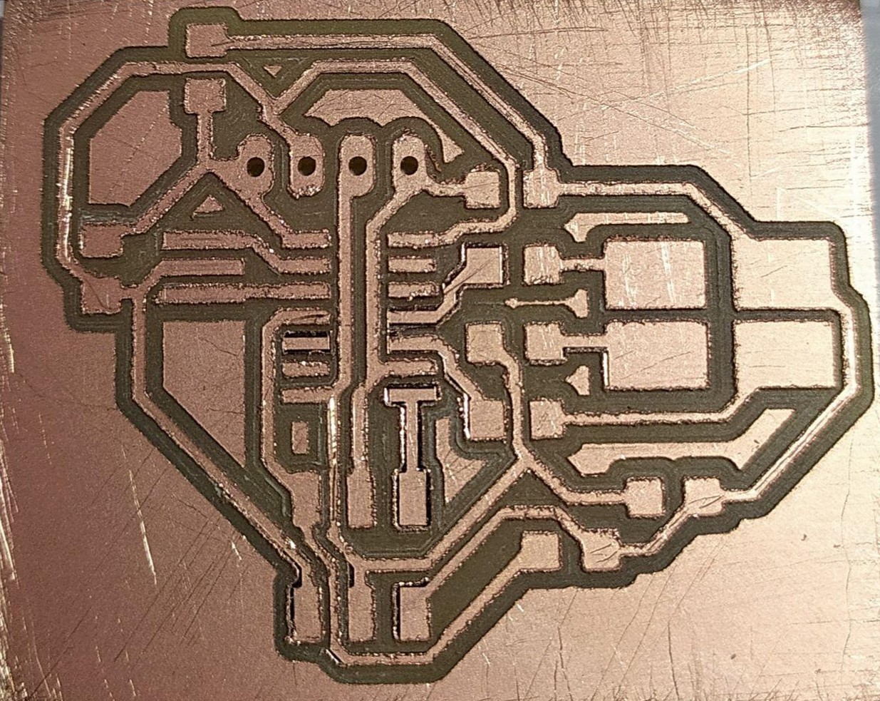
Due to some error in milling mostly due to bit tip the trace does not look good. The marks are caused becasue i used steel wool to remove copper from rough edges.
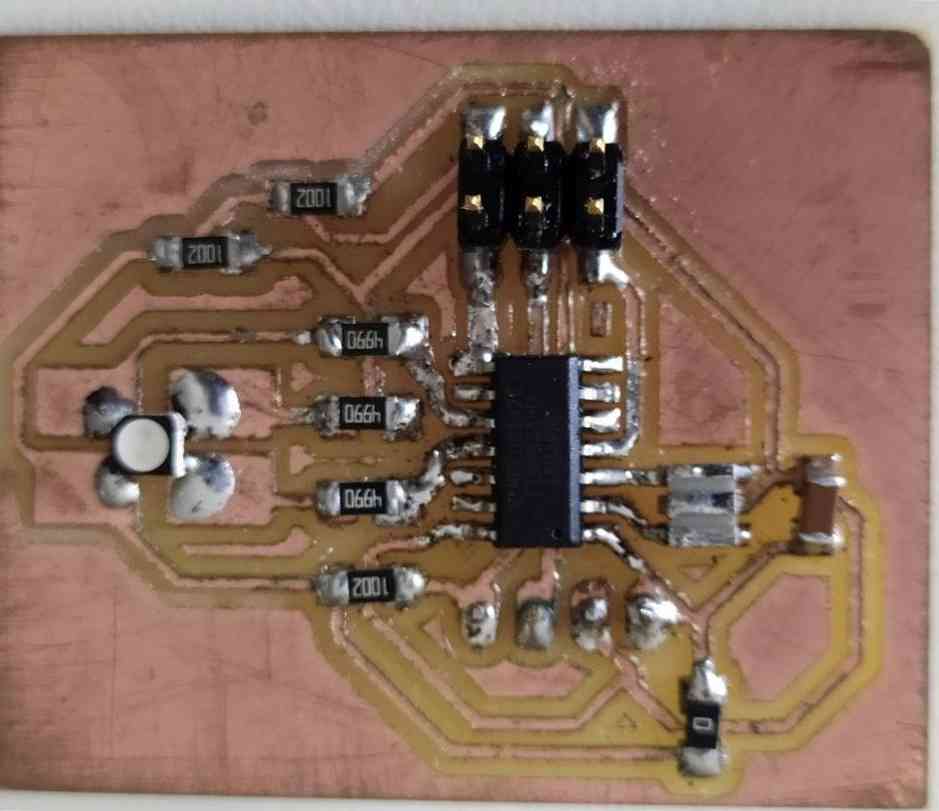
THere was an error in this board also but i fixed it using copper wire and i had to cut a trace. There was an issue with brightness of blue and red led.
Board programing
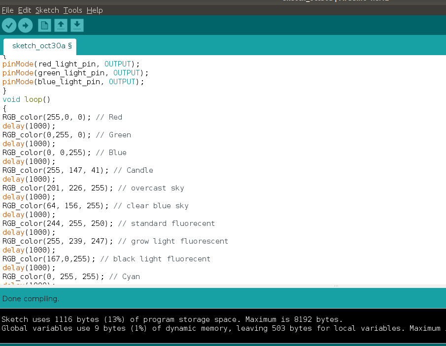
I used Arduinio IDE to program thr output board using USBTiny.So the program is produce several colours. I got colour codes from an reddit link for plently of natural colours. And devloped the program for common annode LED.
int red_light_pin= 3;
int green_light_pin = 1;
int blue_light_pin = 2;
void setup()
{
pinMode(red_light_pin, OUTPUT);
pinMode(green_light_pin, OUTPUT);
pinMode(blue_light_pin, OUTPUT);
}
void loop()
{
RGB_color(255,0, 0); // Red
delay(1000);
RGB_color(0,255, 0); // Green
delay(1000);
RGB_color(0, 0,255); // Blue
delay(1000);
RGB_color(255, 147, 41); // Candle
delay(1000);
RGB_color(201, 226, 255); // overcast sky
delay(1000);
RGB_color(64, 156, 255); // clear blue sky
delay(1000);
RGB_color(244, 255, 250); // standard fluorecent
delay(1000);
RGB_color(255, 239, 247); // grow light fluorescent
delay(1000);
RGB_color(167,0,255); // black light fluorecent
delay(1000);
RGB_color(0, 255, 255); // Cyan
delay(1000);
RGB_color(255, 0, 255); // Magenta
delay(1000);
RGB_color(255, 255, 0); // Yellow
delay(1000);
RGB_color(255, 255, 255); // White
delay(1000);*/
}
void RGB_color(int red_light_value, int green_light_value, int blue_light_value)
{
analogWrite(red_light_pin, 255-red_light_value);
analogWrite(green_light_pin, 255-green_light_value);
analogWrite(blue_light_pin,255-blue_light_value);
}