Fabacademy 2020
Introduction
Interface and application development is an important part of new age devices. We are trying to tell whats in our mind using a virtual input device. In previous week we dealed with creating an input and output board. But this week we want to make an interface or app which can connect with an output board.
I am planing to use processing software which is used to develop interface using the help of visual arts and also using arduino IDE to develop a program to program the output board. I have decided to use my output board which is an RGB board and it would be helpful for me to connect this week to my final project so that i can virtaully control rgb light colours.
Output board
I am planing to use the board which i made during the output devices week.The board conists mainly of an atiny84 microcontroller and an RGB LED.I want to switch on/off and blink the LED using an interface. All the details can be found in theoutput board week.
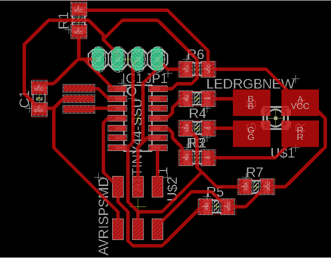
Board file of the output board.
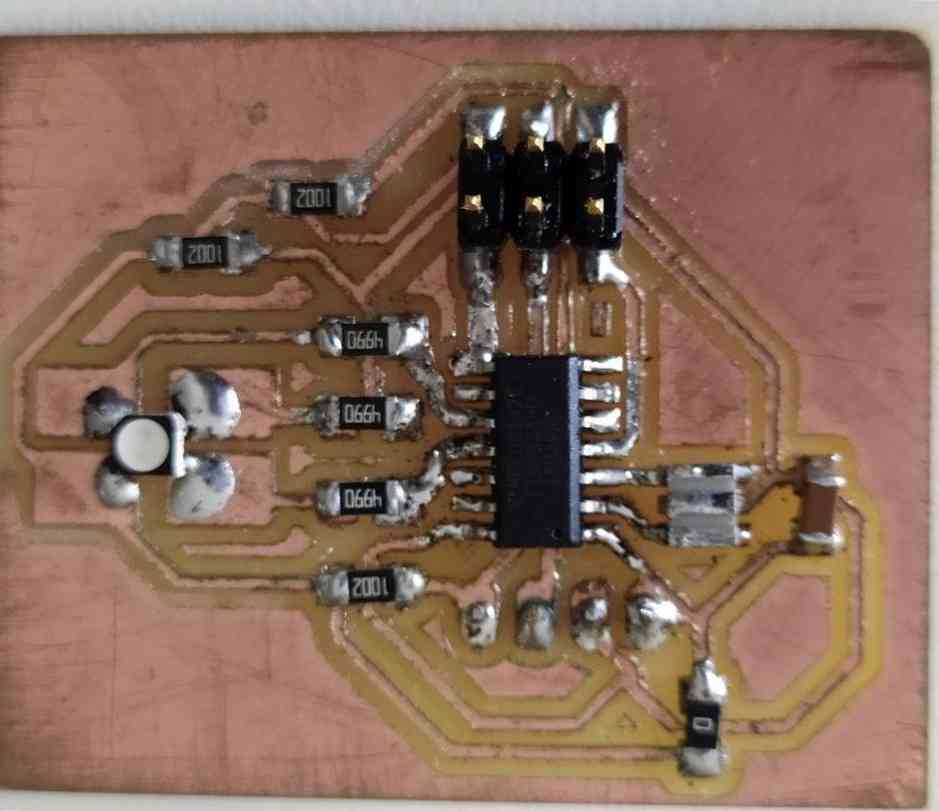
How the output board looks after soldering the commponents.
Group Assignment
The group assignement for this week is explained in detail in the group page. To access the group page click here.
Processing
Processing is a flexible software sketchbook and a language for learning how to code within the context of the visual arts. It is an open-source graphical library and integrated development environment (IDE) built for the electronic arts, new media art, and visual design communities with the purpose of teaching non-programmers the fundamentals of computer programming in a visual context.
It is relatively easy process to download and install processing.It can be downloaded from here.
The interface of processing is similar to arduino so it is easy to learn. after watching few tutorials..
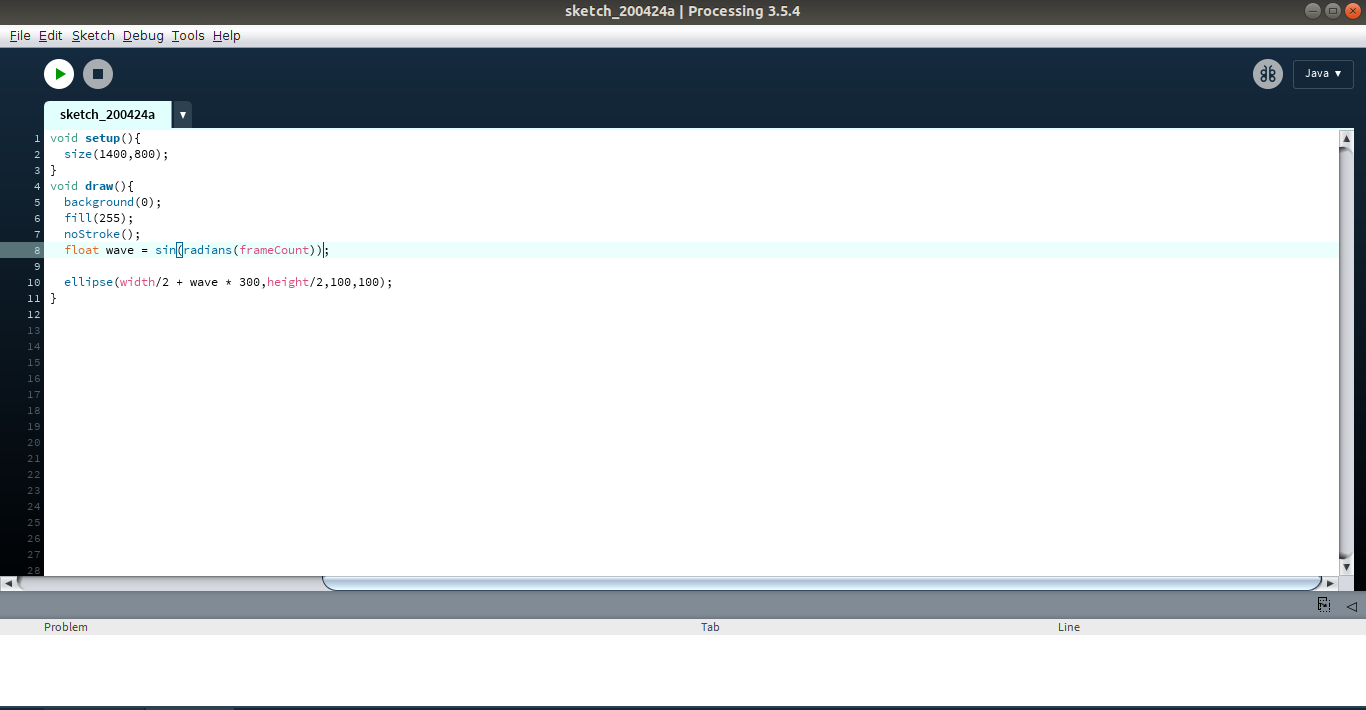
The structures in arduino and processing are almost similar. "void setup" serves a similar role of arduino "void setup" and also the "void draw" in processing is also doing a similar functionality of "void loop" in arduino.
It is fun to experiment with processing since we can visually see what we have programmed. We can use 2 languages to code in processing python mode and java mode.I would be using python mode. After watching few tutorials i tried makinga small animation where a white ball oscillates in a black background
After trying a bit of processing i kept it aside. Further started to work with arduino.
Programming
For the arduino code I just modified my output week code and made it more simple. I made certian set of condition with help of my instructor where i entered various response of my led which i want.
#include

SoftwareSerial mySerial(4, 6); // RX, TX
int alpha;
int red_light_pin= 3;
int green_light_pin = 1;
int blue_light_pin = 2;
void setup()
{
// Open serial communications and wait for port to open:
mySerial.begin(9600);
pinMode(red_light_pin, OUTPUT);
pinMode(green_light_pin, OUTPUT);
pinMode(blue_light_pin, OUTPUT);
digitalWrite(red_light_pin,HIGH);
digitalWrite(green_light_pin,HIGH);
digitalWrite(blue_light_pin,HIGH);
}


void loop() // run over and over
{
if (mySerial.available())
{
alpha=mySerial.read();
mySerial.println(alpha);
switch(alpha)
{
case 0:
digitalWrite(red_light_pin,LOW);
digitalWrite(green_light_pin,HIGH);
digitalWrite(blue_light_pin,HIGH);
break;
case 1:
digitalWrite(red_light_pin,HIGH);
digitalWrite(green_light_pin,LOW);
digitalWrite(blue_light_pin,HIGH);
break;
case 2:
digitalWrite(red_light_pin,HIGH);
digitalWrite(green_light_pin,HIGH);
digitalWrite(blue_light_pin,LOW);
break;
case 3:

digitalWrite(red_light_pin,LOW);
digitalWrite(green_light_pin,HIGH);
digitalWrite(blue_light_pin,HIGH);
delay(1000);
digitalWrite(red_light_pin,HIGH);
digitalWrite(green_light_pin,LOW);
digitalWrite(blue_light_pin,HIGH);
delay(1000);
digitalWrite(red_light_pin,HIGH);
digitalWrite(green_light_pin,HIGH);
digitalWrite(blue_light_pin,LOW);
delay(1000);
digitalWrite(red_light_pin,LOW);
digitalWrite(green_light_pin,LOW);
digitalWrite(blue_light_pin,LOW);
delay(1000);
digitalWrite(red_light_pin,HIGH);
digitalWrite(green_light_pin,LOW);
digitalWrite(blue_light_pin,LOW);
delay(1000);
digitalWrite(red_light_pin,LOW);
digitalWrite(green_light_pin,HIGH);
digitalWrite(blue_light_pin,LOW);
delay(1000);
digitalWrite(red_light_pin,LOW);
digitalWrite(green_light_pin,LOW);
digitalWrite(blue_light_pin,HIGH);
delay(1000);
break;
case 4:
digitalWrite(red_light_pin,HIGH);
digitalWrite(green_light_pin,HIGH);
digitalWrite(blue_light_pin,HIGH);
break;
}
}
}
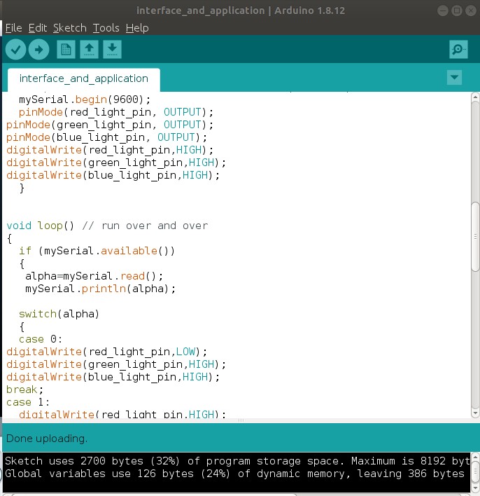
I succesfully uploaded the program to my board.
So my processing program consists of several parts with each part with different function.
import controlP5.*; //import library to draw and control buttons
import processing.serial.*; //import serial library

ControlP5 cp5;  //define cp5 as a ControlP5 object
Serial myPort; //define myPort as a Serial object

PFont ButtonFont; // define this to change button font

void setup(){
size(600,450); // set the windows size
cp5= new ControlP5(this); // creat new ControlP5 object
ButtonFont =createFont("Georgia",20); // set desired font type

cp5.addButton("RED") // Creat RED button
.setPosition(170,150) // position of the button (X,Y)
.setSize(75,75) // size of the button
.setFont(ButtonFont)// Font type of the  button
.setColorCaptionLabel(color(255,0,0));
// Font color of the  button

cp5.addButton("GREEN")
.setPosition(370,150)
.setSize(75,75)
.setFont(ButtonFont)
.setColorCaptionLabel(color(0,255,0));

cp5.addButton("BLUE")
.setPosition(170,250)
.setSize(75,75)
.setFont(ButtonFont)
.setColorCaptionLabel(color(0,0,255));

cp5.addButton("BLINK")
.setPosition(370,250)
.setSize(75,75)
.setFont(ButtonFont)
.setColorCaptionLabel(color(205,0,255));

cp5.addButton("OFF")
.setPosition(270,200)
.setSize(75,75)
.setFont(ButtonFont);

myPort = new Serial(this, "/dev/ttyUSB0",9600); //connect myPort with COM3 where arduino
// is actually connected ^_^
}
void draw(){
background(255,255,255); // background color of the screen
fill(0); // Text color
textSize(30); // text size
text("RGB LED CONTROL", 170,70); // To write the title, the position of the title
}
The above code version defines how should the interface look. The parameters like colour can be changed by varying the colour code, position, size,font can be defined here. As it can be seen below the interface looks like this.
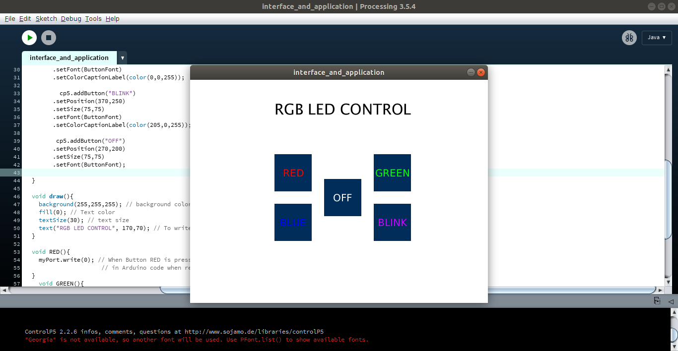
After that the main part of the program is to link the different cases which i have programmed earlier using arduino. So it means when i press differnt buttons in the interface the defined case should be triggered.
void RED(){
myPort.write(0); // When Button RED is pressed send 'r' to serial port
// in Arduino code when recive 'r' the RED color will light
}
void GREEN(){
myPort.write(1);
}
void BLUE(){
myPort.write(2);
}
void BLINK(){
myPort.write(3);
}
void OFF(){  // When Button OFF is pressed send 'o' to serial port
myPort.write(4);// in Arduino code when recive 'o' RGB will  OFF

}
After succesfully entering the program the working can be seen in the video below. I did this week without much error but since i am weak in programming it took me some time to write the programe.
Link to all programing files are given below.
Download all filesIt was interesting week and i understood how an interface works and the unlimted potential it has to offer.