Fabacademy 2020
Introduction
The goal of this week is to build a wire or wireless communication between at least two processors.Embedded electronics is all about interlinking circuits(processors or other integrated circuits) to create a symbiotic system. In order for those individual circuits to swap their information, they must share a common communication protocol. Hundreds of communication protocols have been defined to achieve this data exchange, and, in general, each can be separated into one of two categories: parallel or serial.
From previous weeks of the electronics design i learned more about two microcontrollers that use the Attiny 84.So I decided to use these two microcontrollers and make the communication from one to the other.
Types of communication
Parallel
Parallel interfaces transfer multiple bits at the same time. They usually require buses of data - transmitting across eight, sixteen, or more wires. Data is transferred in huge, crashing waves of 1’s and 0’s.An 8-bit data bus, controlled by a clock, transmitting a byte every clock pulse. 9 wires are used.
Series
Serial interfaces stream their data, one single bit at a time. These interfaces can operate on as little as one wire, usually never more than four.Example of a serial interface, transmitting one bit every clock pulse. Just 2 wires required
Asychronous
Over the years, dozens of serial protocols have been crafted to meet particular needs of embedded systems. USB (universal serial bus), and Ethernet, are a couple of the more well-known computing serial interfaces. Other very common serial interfaces include SPI, I2C, and the serial standard we’re here to talk about today. Each of these serial interfaces can be sorted into one of two groups: synchronous or asynchronous.
A synchronous serial interface always pairs its data line(s) with a clock signal, so all devices on a synchronous serial bus share a common clock. This makes for a more straightforward, often faster serial transfer, but it also requires at least one extra wire between communicating devices. Examples of synchronous interfaces include SPI, and I2C.
Asynchronous means that data is transferred without support from an external clock signal. This transmission method is perfect for minimizing the required wires and I/O pins, but it does mean we need to put some extra effort into reliably transferring and receiving data. The serial protocol we’ll be discussing in this tutorial is the most common form of asynchronous transfers. It is so common, in fact, that when most folks say “serial” they’re talking about this protocol
I2C communication
I2C was originally developed in 1982 by Philips for various Philips chips. The original spec allowed for only 100kHz communications, and provided only for 7-bit addresses, limiting the number of devices on the bus to 112 (there are several reserved addresses, which will never be used for valid I2C addresses).
The I2C communication bus is very popular and broadly used by many electronic devices because it can be easily implemented in many electronic designs which require communication between a master and multiple slave devices or even multiple master devices. The easy implementations comes with the fact that only two wires are required for communication between up to almost 128 (112) devices when using 7 bits addressing and up to almost 1024 (1008) devices when using 10 bits addressing.
I2C requires a mere two wires, like asynchronous serial, but those two wires can support up to 1008 slave devices. Also, unlike SPI, I2C can support a multi-master system, allowing more than one master to communicate with all devices on the bus (although the master devices can’t talk to each other over the bus and must take turns using the bus lines).
Group Assignment
The group assignement for this week is explained in detail in the group page. To access the group page click here.
How to setup the network?
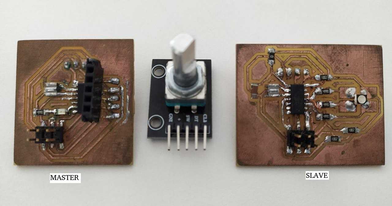
So for this week i have decided to use my input and output board for networking and communication.For input week i made a board using rotary encoder which can be used to control voltage and also as a switch. My output board is RGB board and programmed it to produce various colours. For additional information please check input and output weeks.
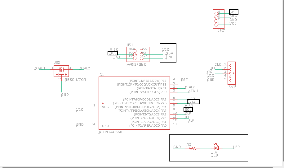
Master board schematics- In the above schematics the marked regions are the ones which should be connected for networking.
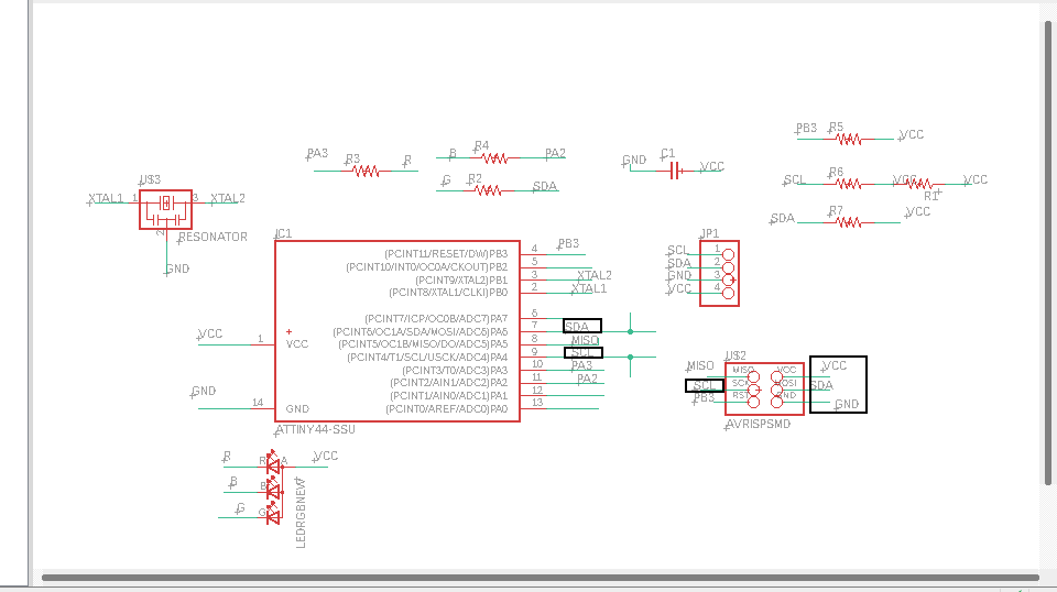
Slave board schematics, the marked ones in the schematics are connected to the slave board.
So i have decided to use my input board as master and my output board as slave. So i want to toggle through differnt colours in output board by rotating the rotary encoder.
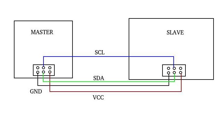
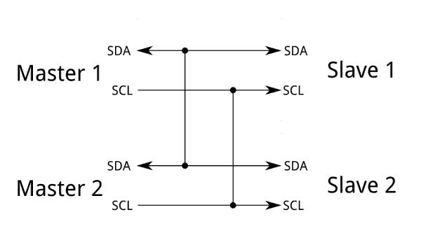
To communicate between the boards, the boards must be connected in appropriate manner. Unchecked connections can cause damage to the board.So above is a rough schematic for how to connect between master and slave. The master sents a signal to the apprpriate terminal in slave to execute a action.
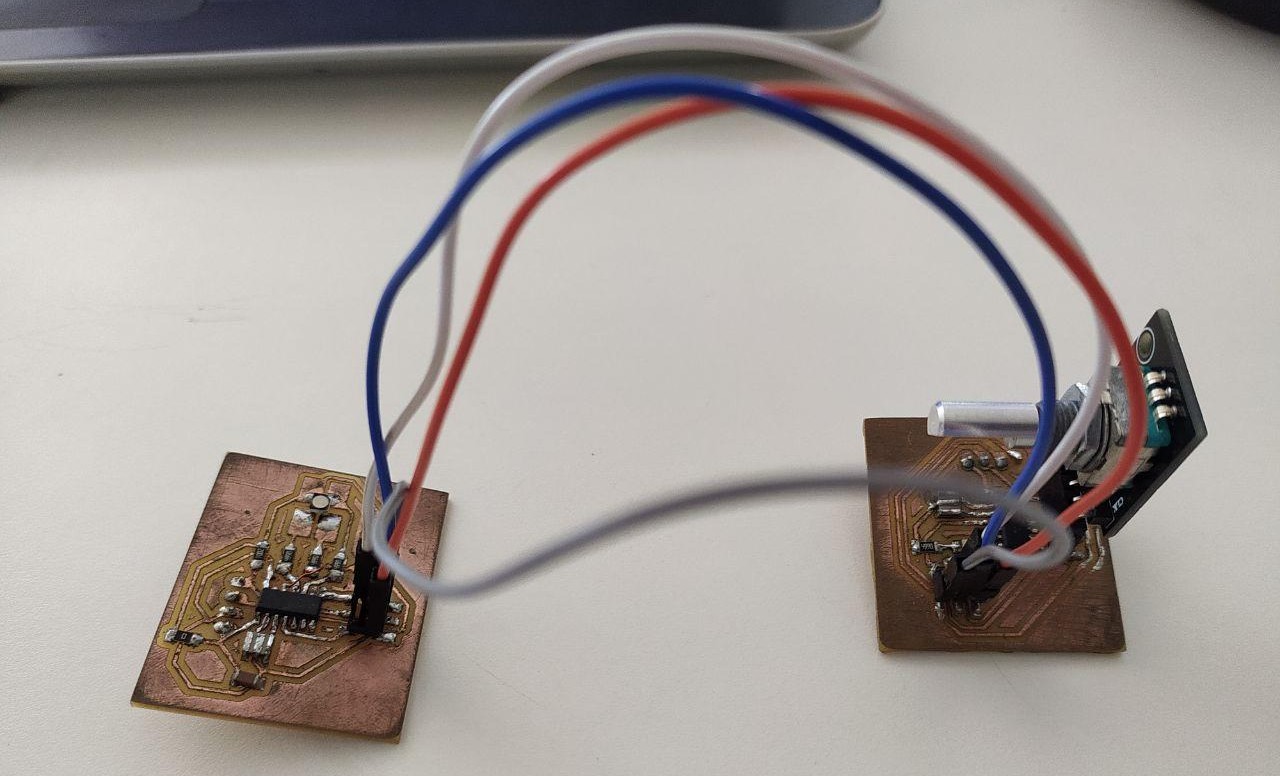
The boards are connected as shown above. The boards are first programmed using USB tiny programmer and then powered using voltage generator.
Programing the Boards.
As mentioned above the intented action is to toggle through different colours in output board using rotary encoder connected to input board. So need to write two programs one mastercode and a slave code. SInce the programing is different from whats done before i had to refer other similar programs.
Master code
Master code used is an updated version of input week code.
//
#include
#include

int brightness;
unsigned long currentTime;
unsigned long loopTime;
const int pin_A = 3;
const int pin_B = 2;
int buttonPin = 1;
const int ledPin = 7;
unsigned char encoder_A;
unsigned char encoder_B;
unsigned char encoder_A_prev = 0;
boolean lastButton = HIGH;
boolean currentButton = HIGH;
void setup()
{
brightness = 0;
Wire.begin();
pinMode(ledPin, OUTPUT);
pinMode(pin_A, INPUT_PULLUP);
pinMode(pin_B, INPUT_PULLUP);
pinMode(buttonPin, INPUT_PULLUP);
currentTime = millis();
loopTime = currentTime;
boolean debounce(boolean last)
{
boolean current = digitalRead(buttonPin); if (last != current)
{
delay(5);
current = digitalRead(buttonPin);
}
return current;
}
void loop() {
currentButton = debounce(lastButton);
if (lastButton == HIGH && currentButton == LOW)
{
brightness = brightness + 255;
}
lastButton = currentButton;
if (brightness > 255) brightness = 0;
currentTime = millis();
if (currentTime >= (loopTime + 5))
{
encoder_A = digitalRead(pin_A);
encoder_B = digitalRead(pin_B);
if ((!encoder_A) && (encoder_A_prev))
{
if (encoder_B)
{
if (brightness + 5 <= 255) brightness += 5;
}
else
{
if (brightness - 5 >= 0)brightness -= 5;
}
}
encoder_A_prev = encoder_A;
Wire.beginTransmission(8);
Wire.write(brightness);
Wire.endTransmission();
analogWrite(ledPin, brightness);
loopTime = currentTime;
}
}
slave code
#include

#define led1 2
#define led2 3
#define led3 1

void setup()
{

Wire.begin(8);
Wire.onReceive(receiveEvent);
pinMode(led1, OUTPUT);
pinMode(led2, OUTPUT);
pinMode(led3, OUTPUT);
}

void loop() {
delay(100);
}

void receiveEvent(int howMany) {
int x = Wire.read();

if (x > 0 && x < 50)
{ digitalWrite(led1, LOW);
digitalWrite(led2, HIGH);
digitalWrite(led3, HIGH);
}
if (x > 50 && x < 150)
{ digitalWrite(led2, HIGH);
digitalWrite(led2, LOW);
digitalWrite(led3, HIGH);
}
if (x > 150 && x < 250)
{ digitalWrite(led3, HIGH);
digitalWrite(led2, HIGH);
digitalWrite(led3, LOW);
}
else
{
digitalWrite(led1, HIGH);
digitalWrite(led2, HIGH);
digitalWrite(led3, HIGH);
}
}
After programing the boards the obtained results are shown below. Colour changes when rotary encoder is rotated.But i couldnt figure out why there is an issue with brightenss of red and blue LED. Maybe its an issue with the mastercode.
This week was a hard week for me . I understood that i still have lot to learn regarding arduino programming .
Download program files