What I did?
3D printing refers to processes in which material is joined or solidified under computer control to create a three-dimensional object, with material being added together (such as liquid molecules or powder grains being fused together). 3D printing is used in both rapid prototyping and additive manufacturing (AM). Objects can be of almost any shape or geometry and typically are produced using digital model data from a 3D model or another electronic data source such as an Additive Manufacturing File (AMF) file (usually in sequential layers). There are many different technologies, like Stereolithography (STL) or Fused Deposit Modeling. Thus, unlike material removed from a stock in the conventional machining process, 3D printing or AM builds a three-dimensional object from computer-aided design (CAD) model or AMF file, usually by successively adding material layer by layer.
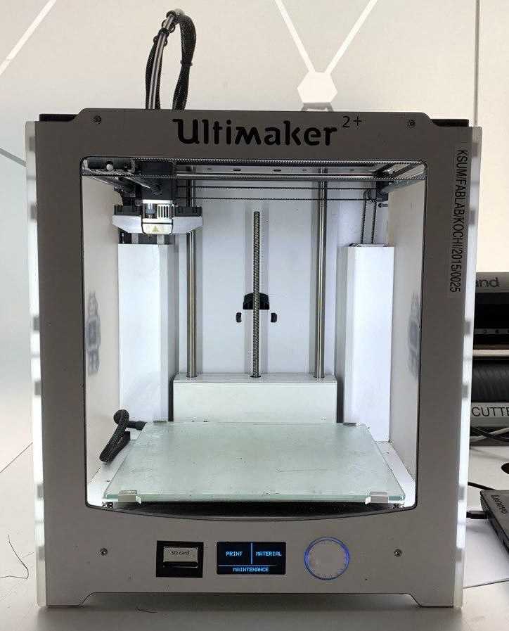
Ultimaker is a 3D printer manufacturer. Their product line includes the Ultimaker 3 family, Ultimaker 2 family and the Ultimaker Original. The company started out as an open-source printer company.Ultimaker 2 is the successor to the Ultimaker Original and was released in September 2013. MAKE magazine classified the Ultimaker 2 as the "best open-architecture 3D printer of 2014" and named it runner-up in the category "Prosumer FFF".
Group Assignment
The group assignement for this week is explained in detail in the group page. To access the group page click here.
3D printing
So far, till present week i only have basic knowledge to design in fusion360. So this week is challenging since i need to design something more complicated. I tried making various simple designs and ended up making an interlocked mobious ring. Since i found the geometry very interesting and also it cannot be produced using substrative milling methods. I found a youtube tutorial on making a mobius ring after learning the technique i improvised and made the design less complicated so that it would be easy to 3d print.
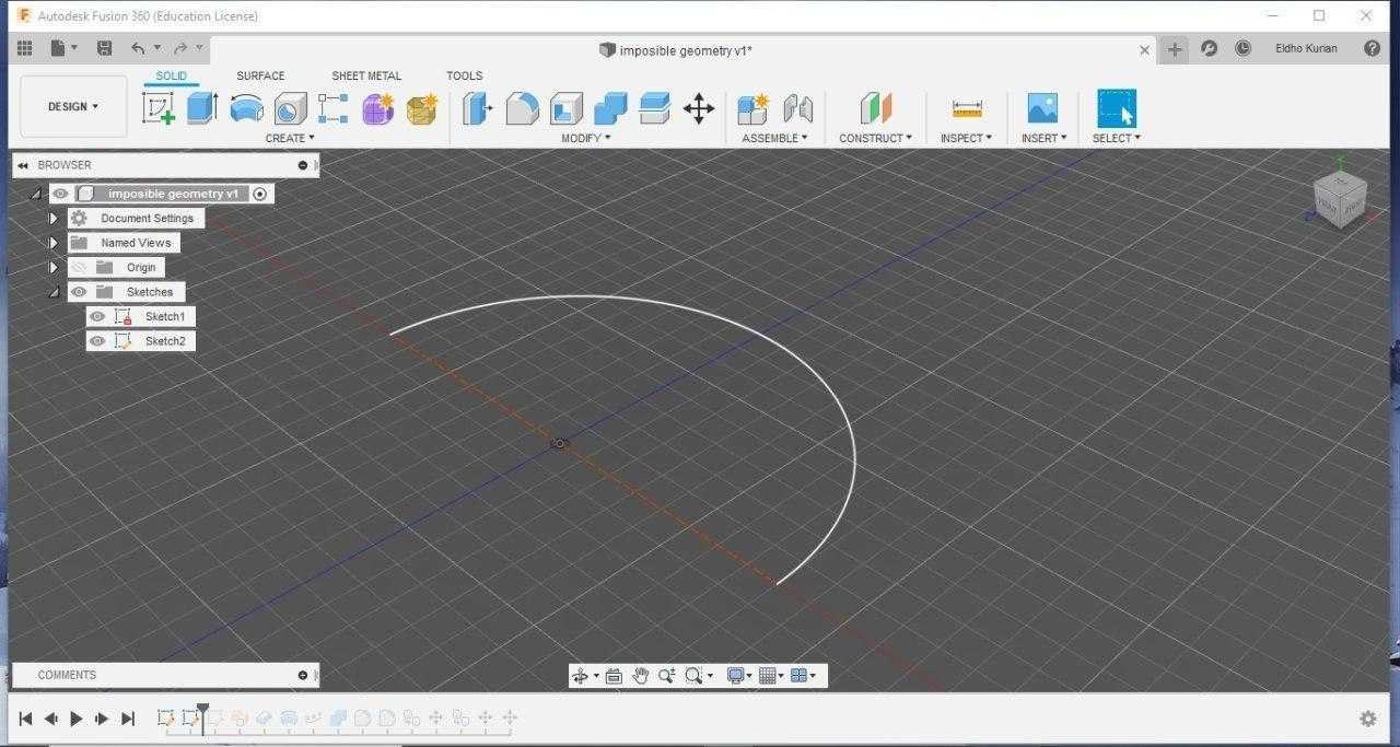
First i constructed an semi circle using the arc tool.
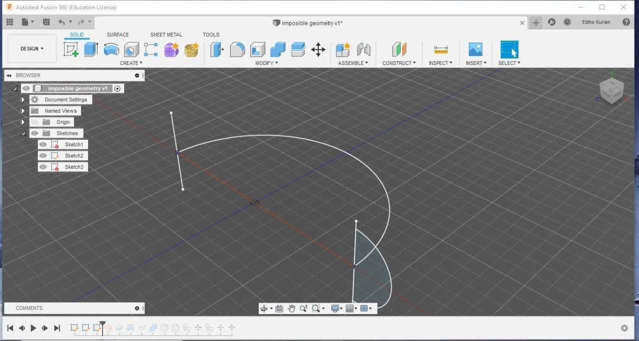
The main aim here is to make a skelton which can be converted to a 3d structure.Since i need a twisted semi circular strip. I constructed a smaller semi circle at one end and line at other end.
Sweeping command in surface section is used and angle of twist given is 90 degree.
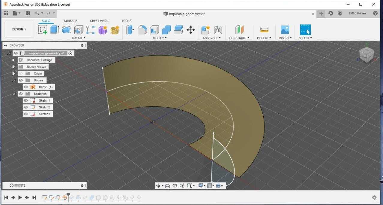
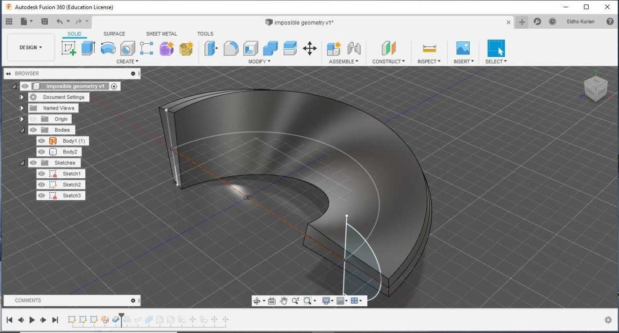
Required thickness is given to the sheet symmetrically
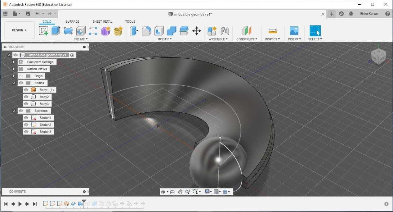
A sphere is constructed at one end using the revolve command.
More spheres are created using form pattern command
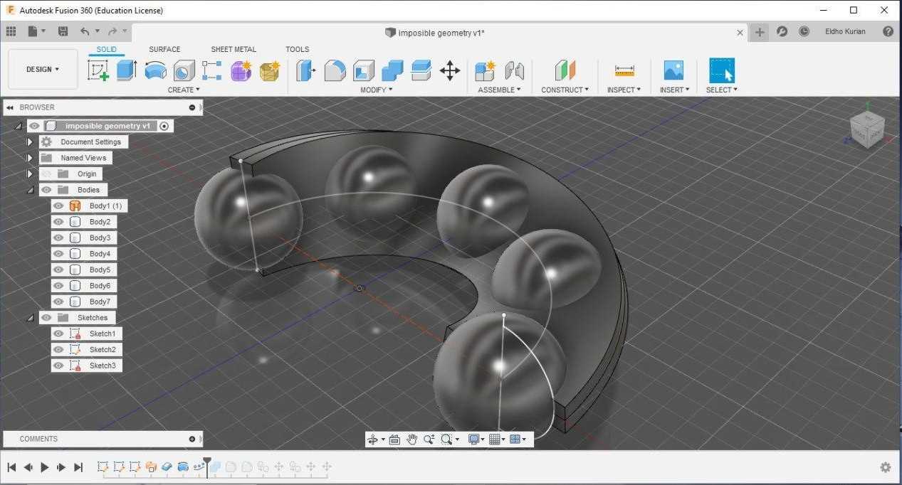
And these spheres are cut out from the sheet using the cut option
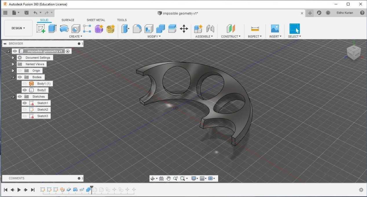
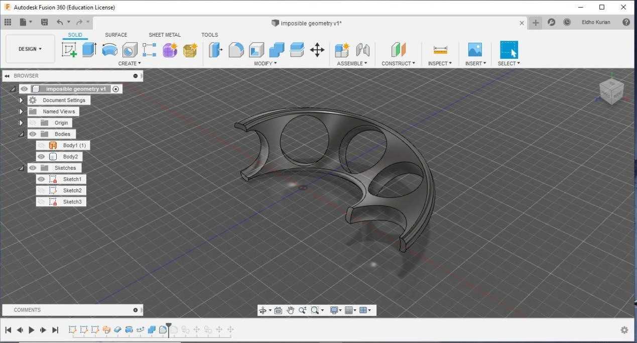
Edges of the cut out area and edges of the sheet are removed using fillet tool.
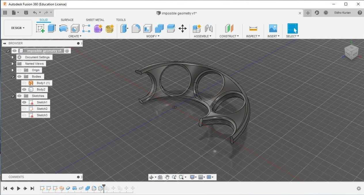
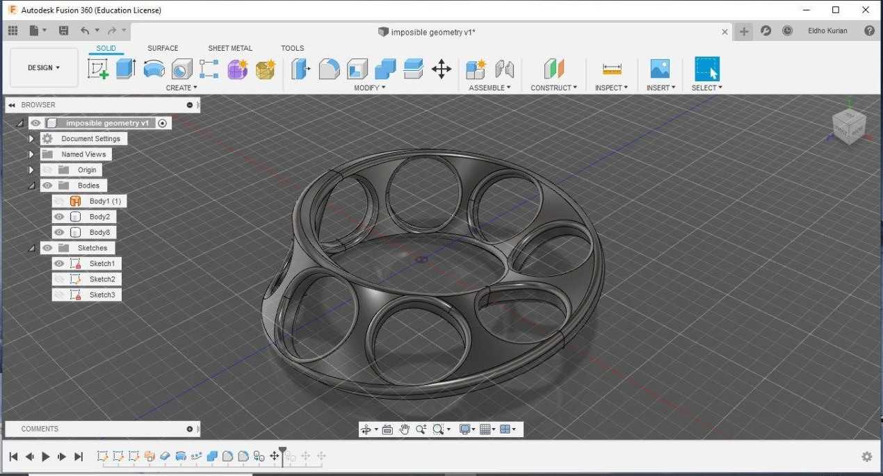
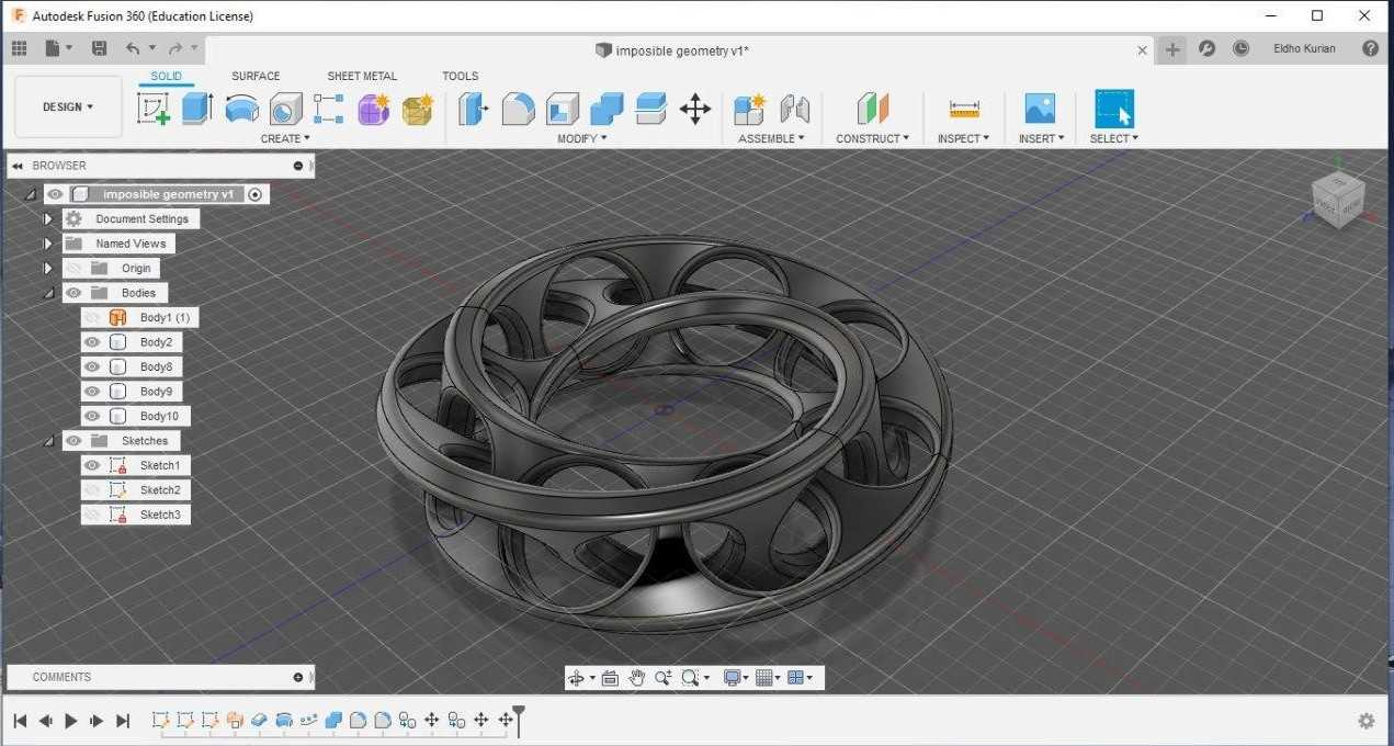
Using the selection tool and giving the pivot point as origin.The section is rotated and copied forming a complete mobius ring
Again using the selction tool the complete profle is rotated to 180 degree to form a copy which is intersects the other ring.
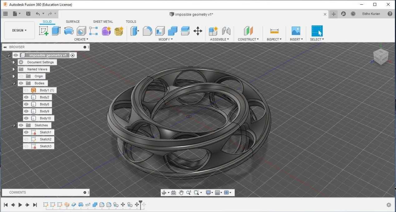
Again one section is selected and rotated to 15 degree to get interlocked mobius rings.
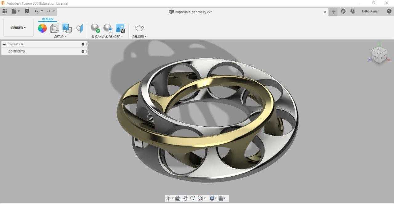
I did rendering using silver and gold material for a metallic touch.
Once the design is complete its exported as a F3D file and this file is used by 3d printing softwares. Since the the f3d file is around 4 mb i have stored it in my googledrive and the link is provided.
Design file
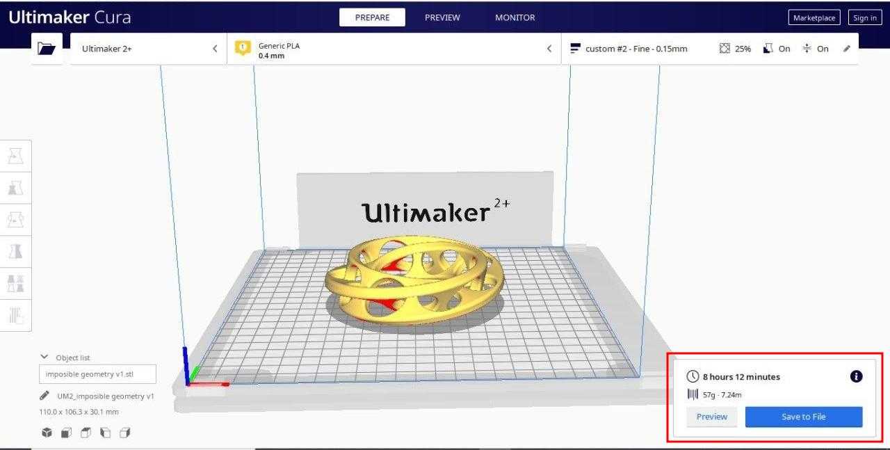
The f3d file is openend in cura for further processing. The file can be easily draged using the mouse and placed on 3d printer workspace. It needs to be properly positioned for slicing and calculaitng the time required to print the structure.
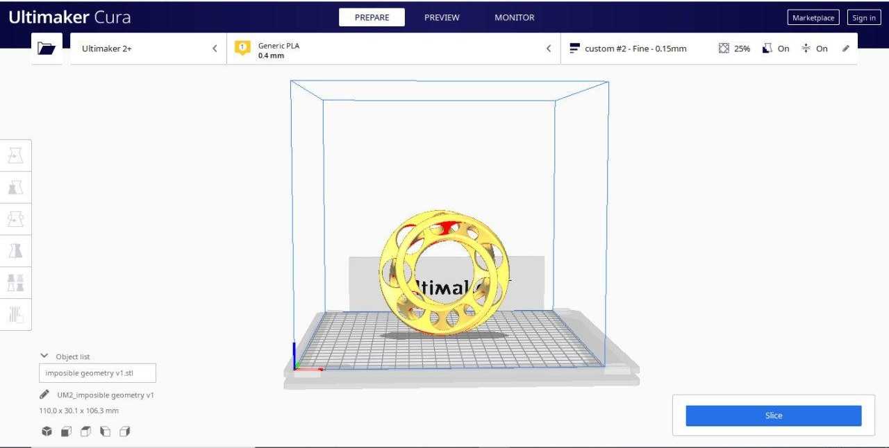
After changing some parameters, mostly are predefined. But the layer height can be changed based how finr you want the print to be. And also the paramters of the support should be evaluated.
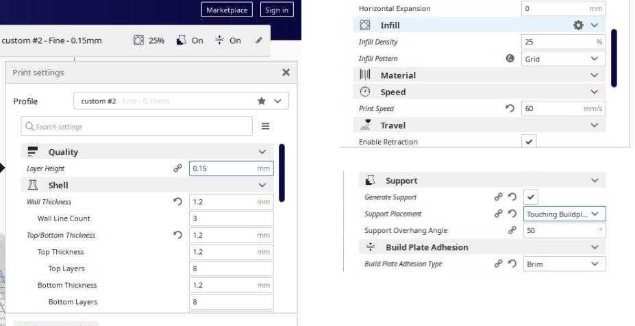
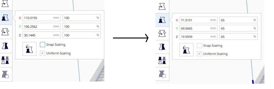
After slicing the time required is really high around 8 hours. So i decided to resize the the print file.
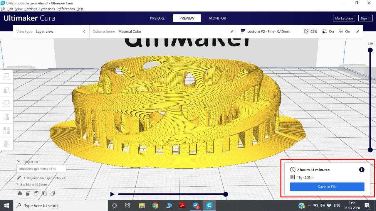
After resizing the printfile to 65% of initial size the print time drastically reduced to 2 hours.
The print file with support can be seen. This file is saved and feeded to the 3d printer
STL file
The print is successful and the support has to be removed. The support is removed using a sharp noser.It is realtievly easy to remove the support because its print with less adhesion
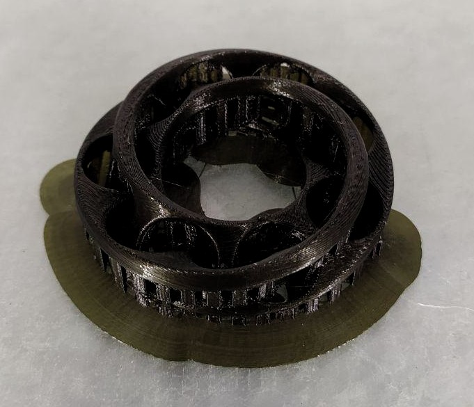
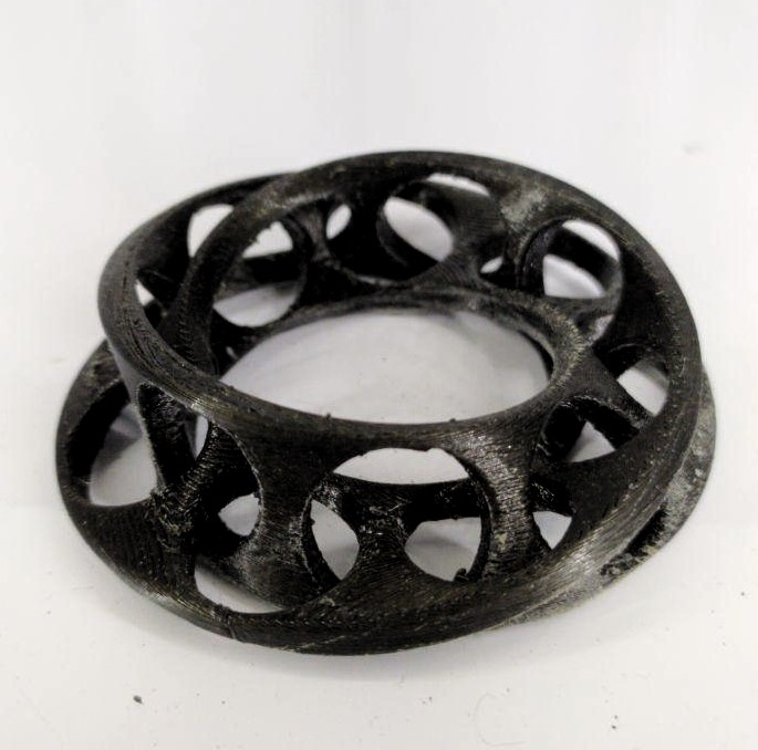
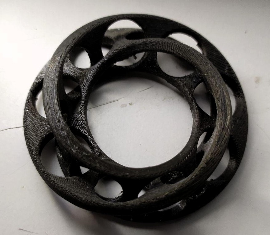
Mobious ring came out good after final polishing.
3D Scanning
3D Scanning is a process to convert Real 3D object to computer File.it's opposit process of 3D Design .Today there somany 3D Scanner's avilable, Depthsensor like Micorsoft Kinect and Intel Real-Sense is a good Example.
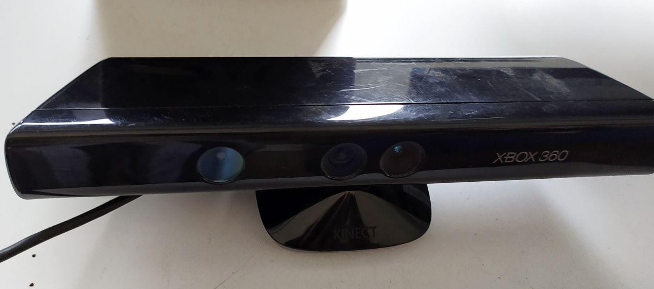
This week for scanning we would be using microsoft XBOX kinect. Initailly we where planing to use ARTEC leo but due to its sotware error to scan file cannot be obtained.
Kinect (codenamed Project Natal during development) is a line of motion sensing input devices that was produced by Microsoft for Xbox 360 and Xbox One video game consoles and Microsoft Windows PCs. Based around a webcam-style add-on peripheral, it enables users to control and interact with their console/computer without the need for a game controller, through a natural user interface using gestures and spoken commands.
Kinect is most compatable with microsoft app 3d scan, but unfortunately 3d scan was not detecting the depth sensor. So I used KScan 3D Software to scan which is a free software which can be downloaded from here
.jpg)
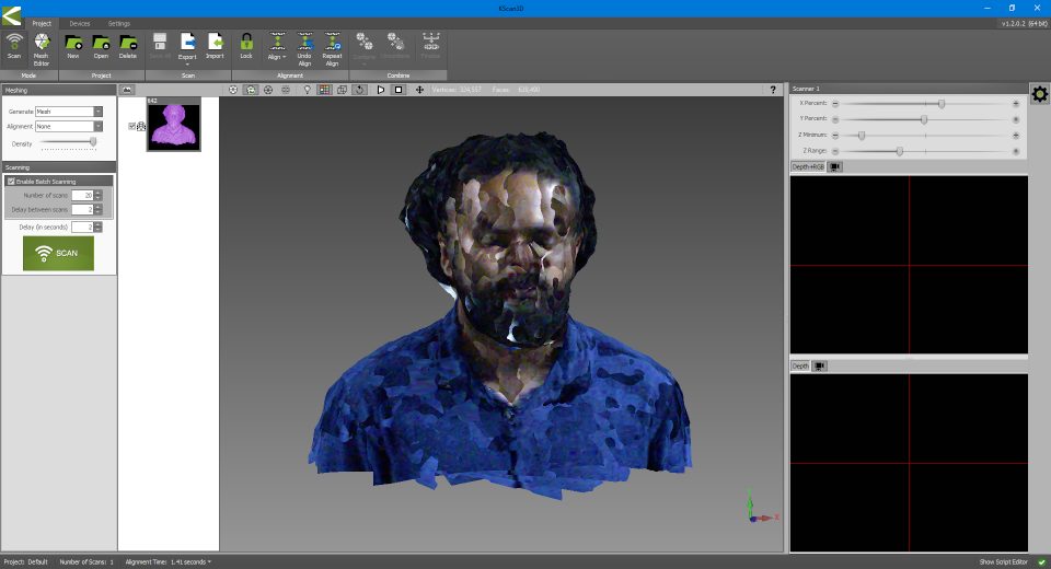
In KSCAN initially we have to position the focus on the object by changing x,y and z coordinates. And then scan images, in my case i took 20 images from different angles.
Click Align to arrange the different dcans into one complete scan.
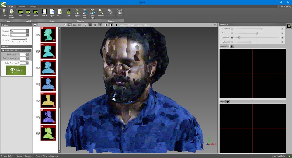
Once the the scan gives decent result all the images can be combined into one file by clickingCombine
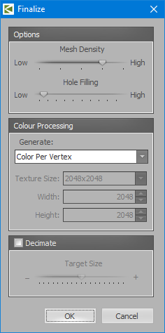
Next step is to make it into 3d mesh format by clickingFInalize images
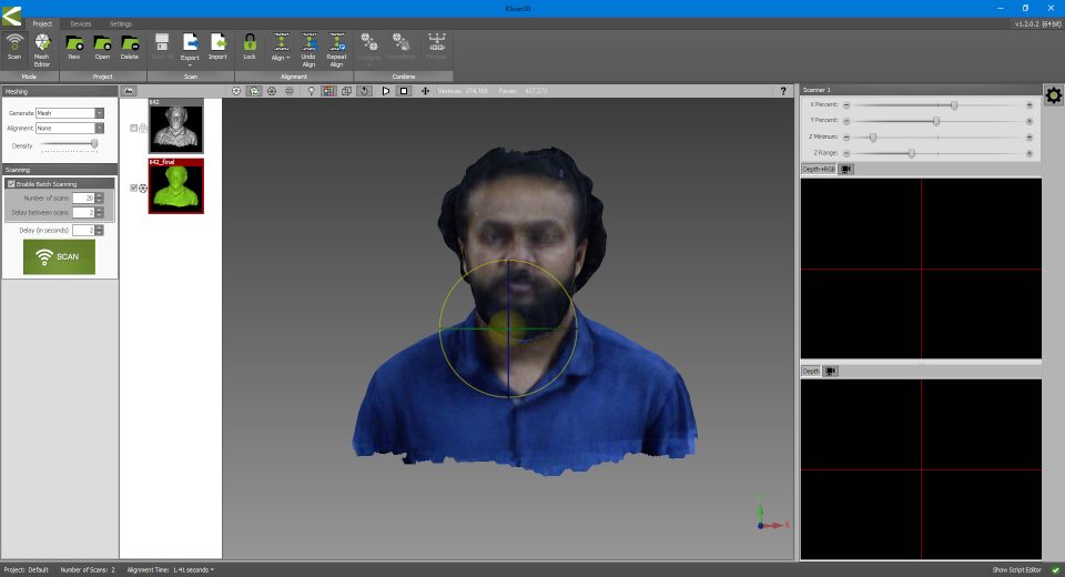
The mesh file obtained and it can be edited or sculpted using other softwares. FIrst we should export this file as .stl for further editing.
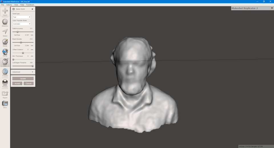
Since my scan file has small openings (regions which didint come to frame while scanning). I have to edit the file so that i can make it into a 3d printing format. I used meshmixer which is a meshediting tool which can be downloaded from here
click mesh edittool to create solid structure of the scan. This file is saved as .stl
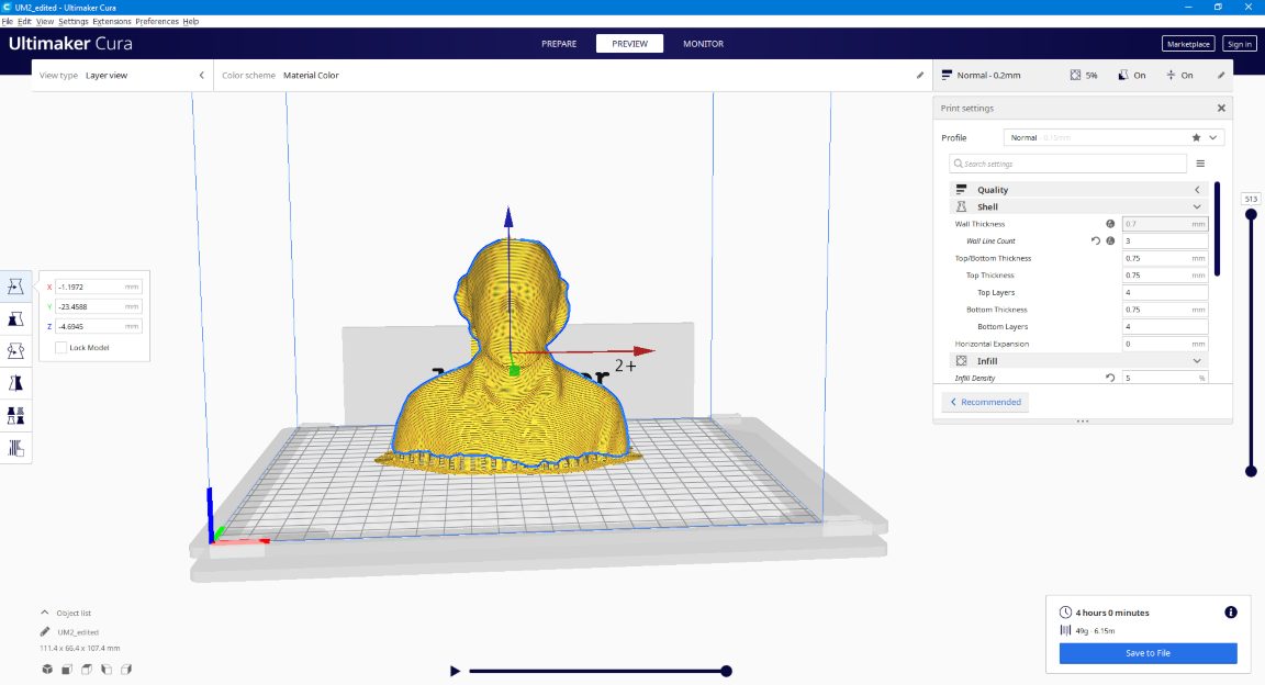
The file is sliced in CURA and is set for 3d printing.
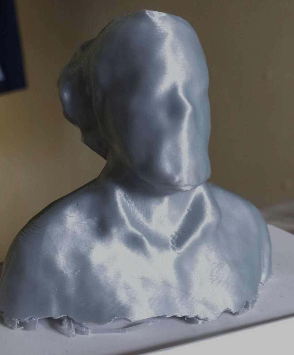
The 3d printed file. Eventhough it doesnot look exactly like me it is close to my distinct features. In future i would like to check how the print quality changes by using high qaulity scanners. SInce the files are huge the files are stored in my google drive and the link to download is given below.
Scanning filesGroup Assignment
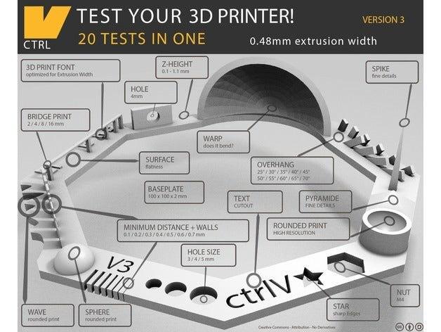
The main objective is to make a test print where all parameters of a 3d printer can be tested. Mainly several criterias listed below are tested and checked whether the printer can accurately print the test subjects
The test file used is downloaded from thingverse website.The link to the file is given below
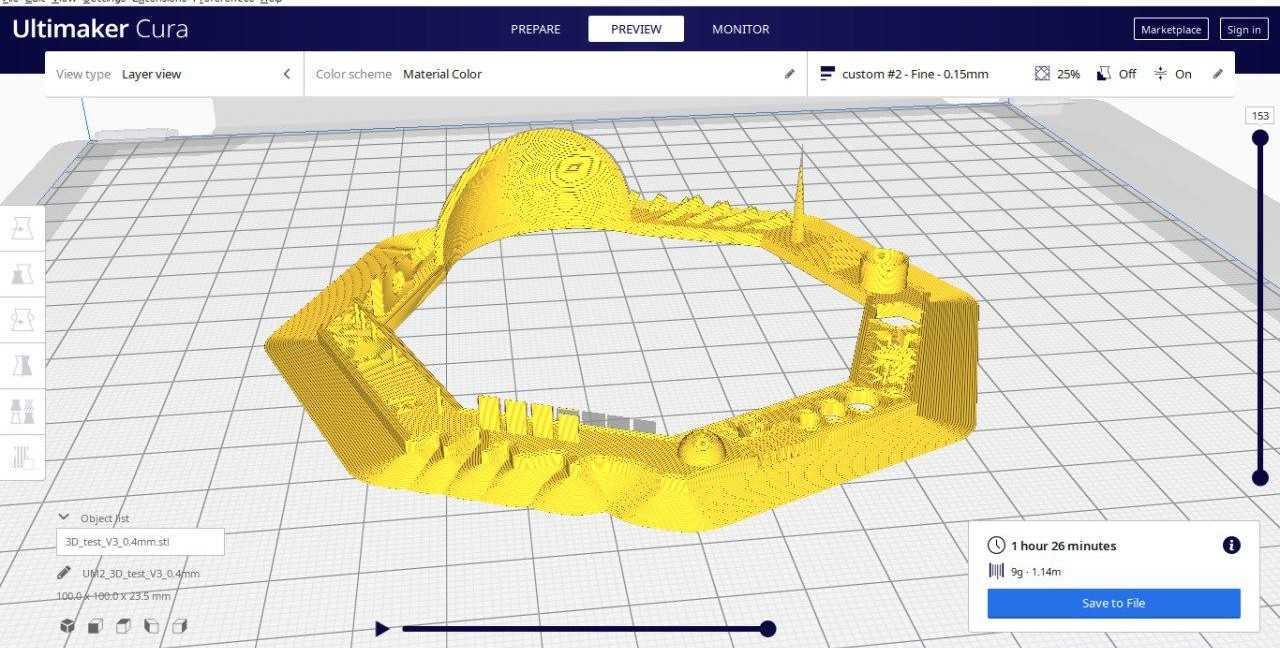
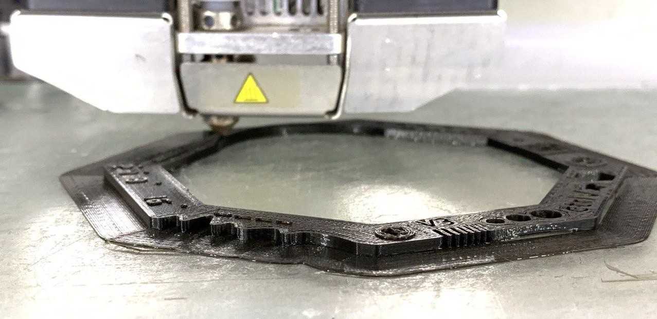
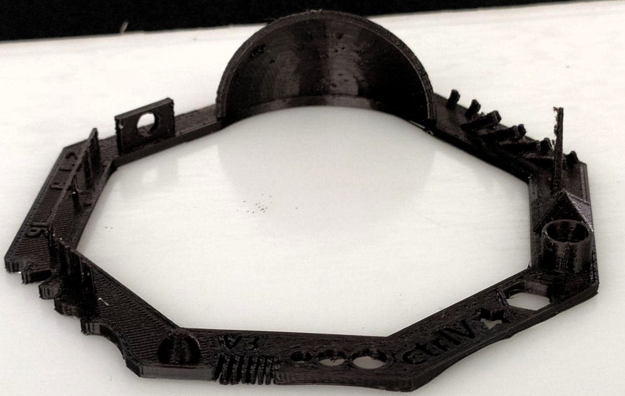
Test print
Print Comparison
| Test paramter | Print Quality | Print Output |
|---|---|---|
| Nut, Size M4 Nut should fit perfectly | As it can be seen Size m4 fits perfectly | 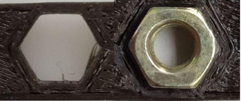 |
| Wave, rounded print | Waves formed are smooth in appearance | 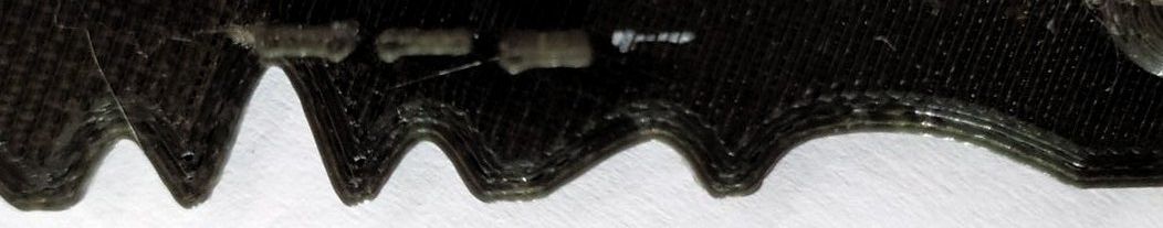 |
| Star, Sharp Edges | Edges are not sharp but curved. | 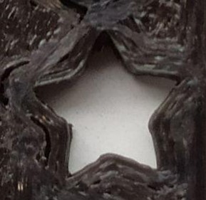 |
| Name, Complex Shapes | Name printed is near to perfect. | 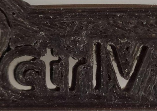 |
| Holes, Size 3, 4, 5 mm | Diameter of the circle printed shows dimension lesser than expected. 2,78,3.78,4.76 mm respectievly. | 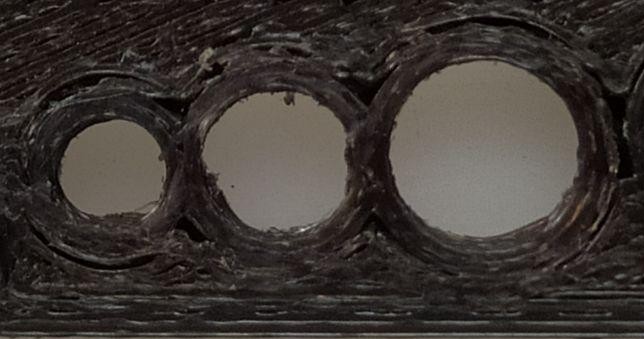 |
| Minimal Distance: 0.1, 0.2, 0.3, 0.4, 0.5, 0.6, 0.7 mm | There is a clearance between each segment but its not measured since its really minute | 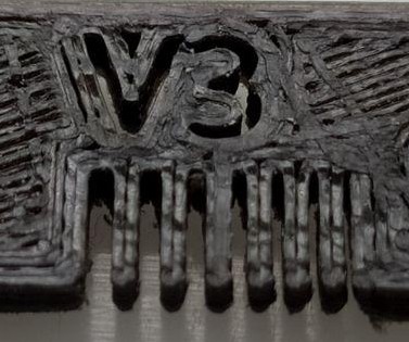 |
| Z height: 0.1, 0.2, 0.3, 0.4, 0.5, 0.6, 0.7, 0.8, 0.9, 1.0, 1.1 mm | There are 11 height variations but in the test print there are only 7 paramters.Starting from 0.23,0.43,0.61,0.74,0.89,1.09,1.21 | 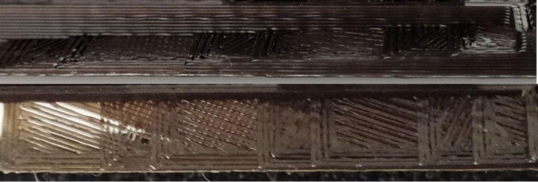 |
| Wall Thickness: 0.1, 0.2, 0.3, 0.4, 0.5, 0.6, 0.7 mm | only three walls where printed, with the last three thickness which are 0.57,0.77,1.08 respectievly | 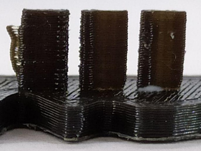 |
| Bridge Print: 2, 4, 8, 16 mm | Bridge is formed between each pillars but some with tiny protrusion | 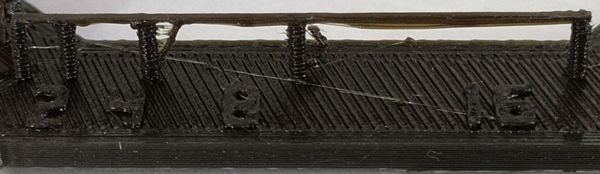 |
| Sphere, Rounded Print 4.8mm height | sphere height - 3.12 | 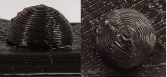 |
| Sphere Mix, 7 mm height | 4.9 mm height | 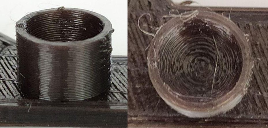 |
| Pyramid, 7 mm height | pyramid 4.8 mm | 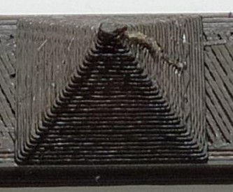 |
| Overhang: 25, 30, 35, 40, 45, 50, 55, 60, 65, 70° | Overhangs show stability but slight defects | 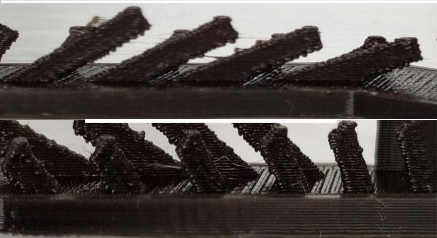 |
| Warp, does it bend? | Warp came out perfect but inside the warp there are tiny globules of PLA | 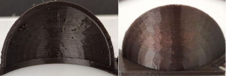 |
| 3D Print Font, optimized for 3D printing | Fonts are almost good | 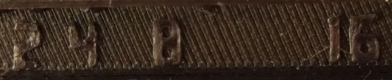 |
| Surface, Flatness | Surface came out well | t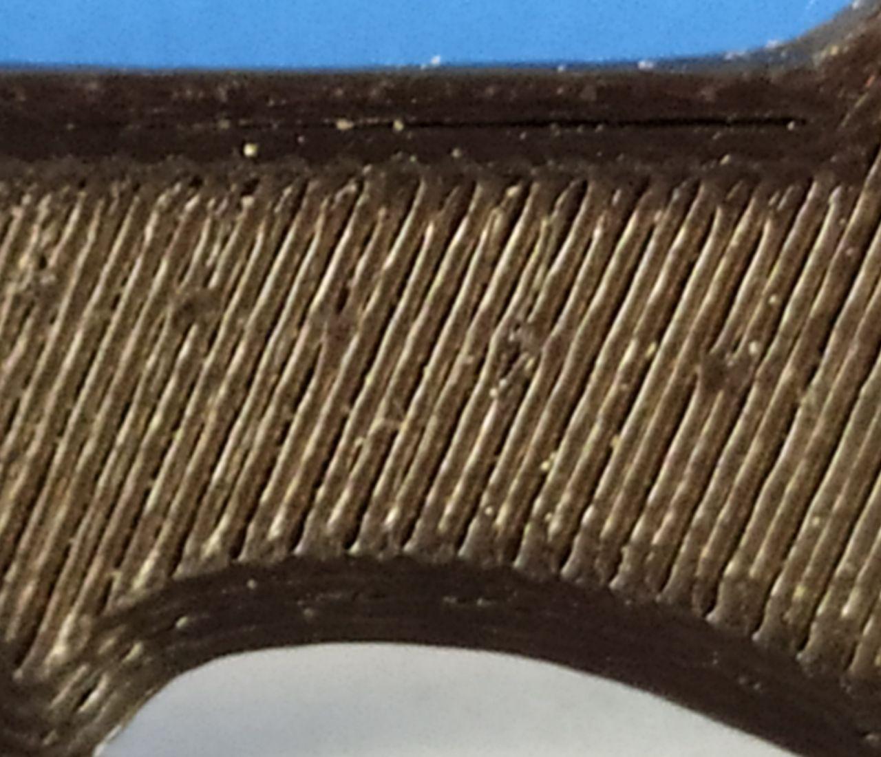 |
| Spike, minimum Layer Time, 21 mm height from Bottom (include Baseplate) | Spike height from base is 17.74 mm | 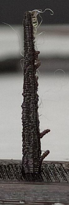 |
| Hole in Wall, 4 mm diameter, check for proper print | Hole is 4.15 mm diameter | 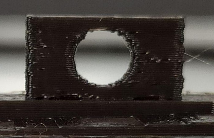 |