5. Electronics production
This week is absolut terra incognita to me. Literally, I have never ever solder an electronic component in my life. I have only used solder maybe once or twice to try to fix a loose cable, at most. And I am both excited and worried about it: excited, because it is a skill that I really want to learn; worried because neither my hands or sight are what they used to be.
Milling the pcb - Characterizing the machine
My first challenge is to successfully mill a pcb board, not having a dedicated desktop CNC mill. During the lecture, Neil talked about a repeteability of just a couple thou, so I have to check if the tool that I have at hand is precise enough. I decided to skip at first the test pattern, and jump straight to mill Brian's ISP.
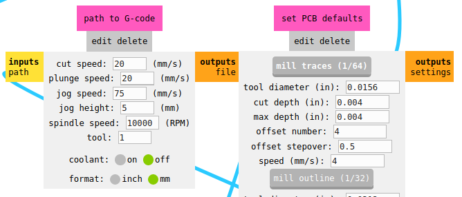
In order to get the g-code, I first used mods community edition, using the generic G-code mill 2D PCB. Since it was the first time I used it, I left the default settings, just to check how it worked:
- Feed: 20 mm/s (1,200 mm/min)
- Speed: 10k rpm
- Pass depth: 0.1 mm
- Tool dia: 1/64"
I am quite used to cut, mostly plywood, at much higher feedrates, so the 1,200 mm/min seemed ok to me. But when the CNC started cutting, it was way too slow. I had a look at the G-code file, and found F20.0000, instead of F1200.0000. My machine was expecting mm/min instead of mm/s. I searched and replaced the code and got it back running. The tracing seemed smooth, and the end mill did not break, even though it was a fairly cheap one, at about 1.40€/piece. What I do not like about it is that the flute is way too long.
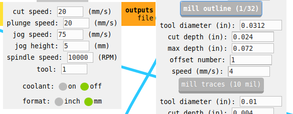
To cut the outline, I switched to the 1/32 end mill, and again, used the default mods ce settings, which were:
- Feed: 20 mm/s (1,200 mm/min)
- Speed: 10k rpm
- Pass depth: 0.6 mm
- Tool dia: 1/32"
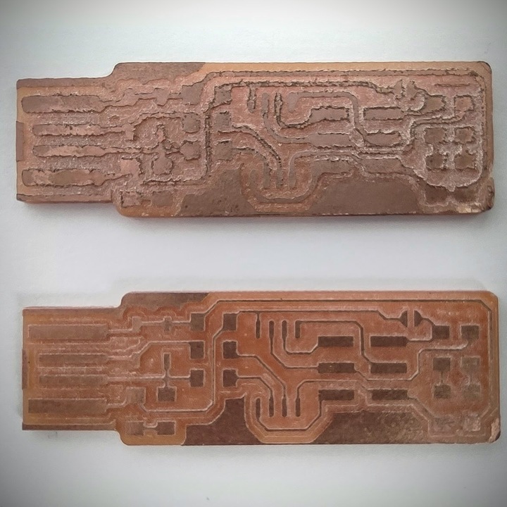
The pass depth of 0.6 mm was too much for my long end mill, so it broke right away, so I lowered the pass depth to 0.25 mm, less than half the tool diameter, to be on the safe side. This time, it worked. I cleaned up the the pcb, and to be honest, did not like the results at all. At first, I did not know what the problem was, if the CNC mill, the settings used or the cheap endmills.
I started the debugging process with the machine settings. Years ago I learned the hard way about feeds & speeds cutting plywood, and unfortunately the internet is full of myths, wrong assumptions and bad ideas in this matter. But I found a source that I thought would be trusted, this blog entryby Emily Shore of Bantam Tools, makers of the acclaimed Othermill. The settings I used to mill the traces were this time:
- Feed: 6 mm/s (360 mm/min)
- Speed: 16k rpm
- Pass depth: 0.1 mm
- Tool dia: 1/64"
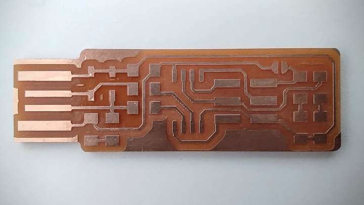
And this time around, the results were way better:
I went on testing with some more feeds and speeds, and really can not tell a lot of a difference betwen these, all milled at 18k rmp and feeds 240, 300 and 360 mm/min. I also set the jog height to 2 mm, since the spindle cycles up and down quite a few times. I will probably stick to 18k 300 mm/min, since the outcome looks slightly better, and takes just 50 more seconds to do the job:
- Feed 360 mm/min Time: 6:02
- Feed 300 mm/min Time: 6:52
- Feed 240 mm/min Time: 7:40
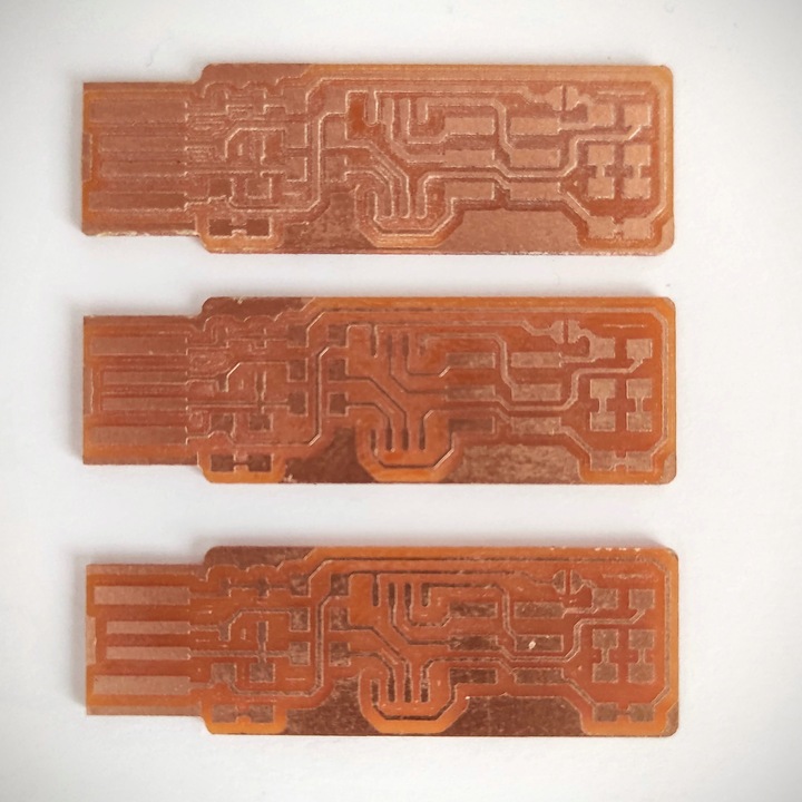
Once properly clean, the pcb looked quite good, with fairly nice straight traces and evenly removed pockets:
Lastly, I milled the line test traces with the 1/64" end mill, and honestly, I am quite pleased finding how thin this machine can leave a trace. I'd say it is more than enough for a novice like me. Clearence between tracks can be the tool diameter, 0.4mm, and track width could eventually be even thinner.
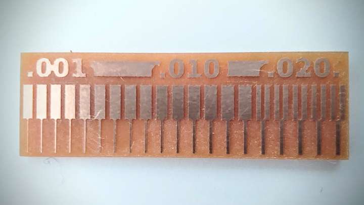
By the way, I am quite happy with the results, and they actually look much better in real life than in picture, and wait till the end of the video to have a look at the machine I used...
Stuffing the board
I first prepared my parts list, and checked that had all the components. But then realized that I had wrong resistors size... They are tiny, 0805 instead of 1206. My wrong for not checkign deltas properly. I went to our local electronics shop, and they do not sell smd 1206 in small batches, so I tried amazon. The problem then was the delivery time, too late for the assignment. Hopefully, I phoned one of my classmates, since 3 out of the 5 students from Fab Lab Leon are remote students from Madrid, and Lorena lent me a hand.

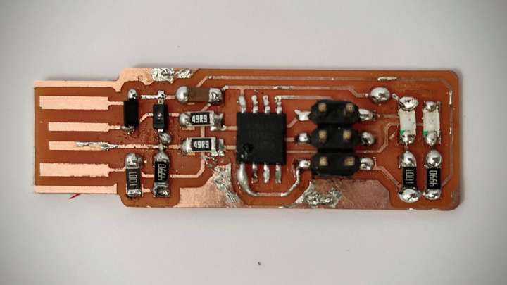
Once I went on to start soldering components, I first practiced in the ugly pcb. Everything felt really small, and really I could no see very well. Then, I went on to try to solder the AT Tiny first, since it is in the middle. Somehow, I got it a bit wrong, and when I tried to desolder it, I ripped off one of the traces, rendering the board useless (at least for me). So, I was definetly not up to the task. I took a few resistors and practiced filling completly this board, triying to gain some confidence
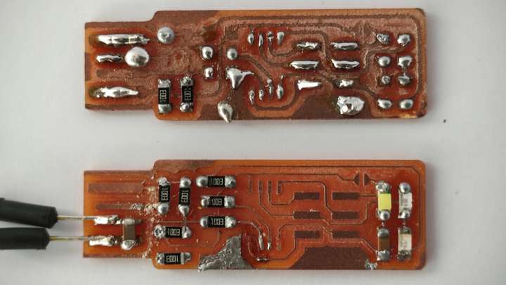
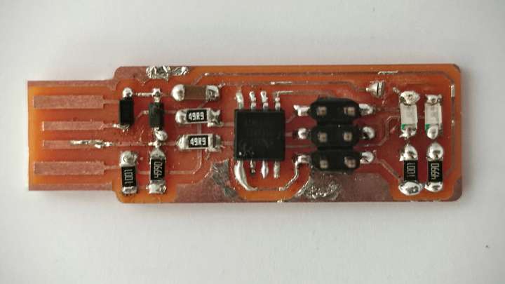
Next day, after tons of blood, sweat and tears, and a brand new roll of 0.6 mm gauge soldering wire, I managed to have my firs board finished. I carefully tested continuity, and at least the LEDs work fine when checked with the multimeter (thanks Nuria). I know it certainly looks bad, but bear in mind, dear Global Evaluator, that this is the very first I attempt, and from here, I shall do nothing but improve... Let's now see how the programming goes...
I know the soldering is lumpy, and not good looking at all. So I will have to work harder in this area.
Programming the board
To program the board, I will first try to use an Arduino as an ISP. I really do not know how tough the task, is, so let's get to it. I first downloaded the Arduino IDE. I followed the instructions to install it, which were very straightforward
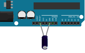
Next, I needed to turn my Arduino as an ISP, and honestly, no clue on how to achieve it. I found this Instructable, by dmjlambert, that went in great detail into it. Not that I understood a lot, so I guess I will have to review it again. But basicaly, Iunderstood how to connect a 10uF capacitor between RST and GND.
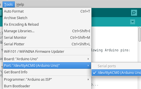
Then, after selecting the right port in the Arduino IDE tool, I uploaded successfully the sketch, no changes made, since it stated that pins 10, 11, 12 and 13 can be used directly with the Arduino One. The wiring goes as follows:
| Function | Arduino Uno | FabISP |
|---|---|---|
| RST | 10 | 5 |
| MOSI | 11 | 4 |
| MISO | 12 | 1 |
| SCK | 13 | 3 |
| GND | GND | 6 |
| VCC | 5V | 2 |
The next step, after installing and downloading both Avrdude, sudo apt install avrdude gcc-avr avr-lib make, and the firmware source code, is to edit the Makefile configuration for avrdude

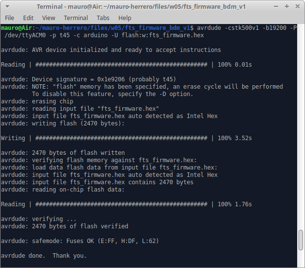
I also changed the programmer name, since it was mentioned in Brian's tutorial: PROGRAMMER ?= arduino, and after an error also changed MCU = t45. I was still geting an error, refering to avr "can't open device 'usb'", so I tried to flash manually, using avrdude -cstk500v1 -b19200 -P /dev/ttyACM0 -p t45 -c arduino -U flash:w:fts_firmware.hex. This time, it apparently worked!!!
Sorry, but it meant so much for me that I just feel this video should come before any further explanation. It will be a faithful memory of the tears I shed during this week.
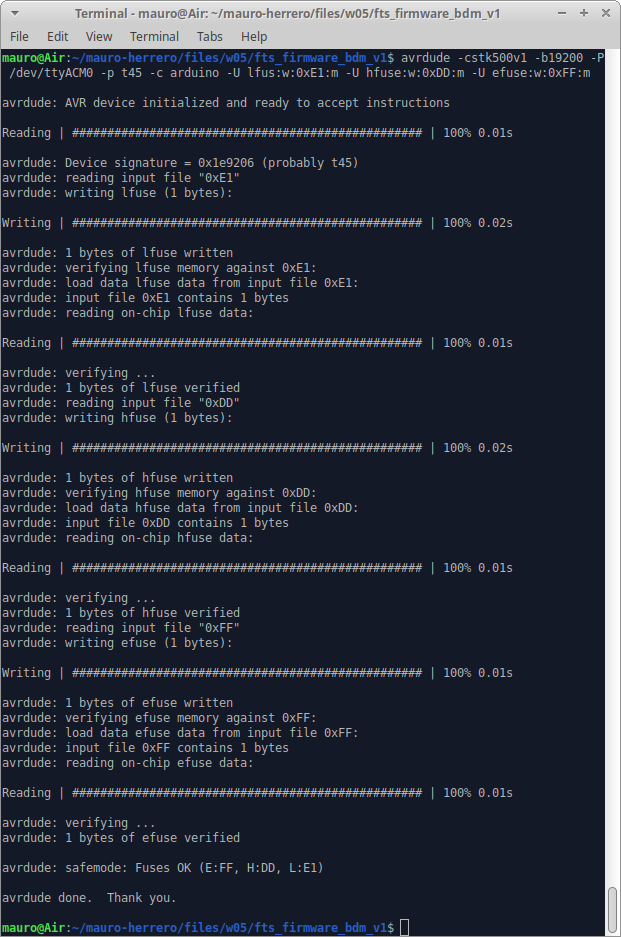
When running the make fuses command, I also run into the same usb error. So, again, I ran it manually: avrdude -cstk500v1 -b19200 -P /dev/ttyACM0 -p t45 -c arduino -U lfus:w:0xE1:m -U hfuse:w:0xDD:m -U efuse:w:0xFF:m, and got this outcome:
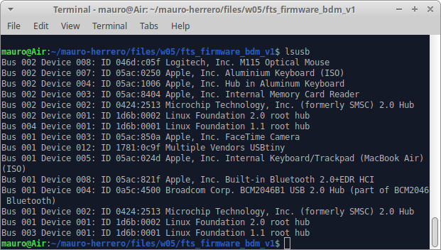
Then, I tested it, first unplugging the setup and plugging the FabISP to the computer through an USB cable extension, and typing lsusb, and found the magic "Multiple Vendors USBtiny":
Finally, I ran make rstdisbl, and for the third time, I got the "can't open device 'usb'". This time, I looked a bit closer to the Makefile, and removed the -P usbpart from the rstdisbl: section, and got it working. Lastly, I removed the bridge on the solder jumper.
Next, I will again make a second version of the Fab Tiny ISP, just to improve my brand new soldering skill. I have to admit that, even I just covered the bare minimum for this assignment, it has been really hard for me. I literally went into tears when I first saw the green flashing LED. I am quite sure that I will keep a fond memory of that very moment. Thanks, Nuria, thanks, Adrian, thanks, Pablo, thanks, Brian, thanks Neil and everybody else in this network.