Final project
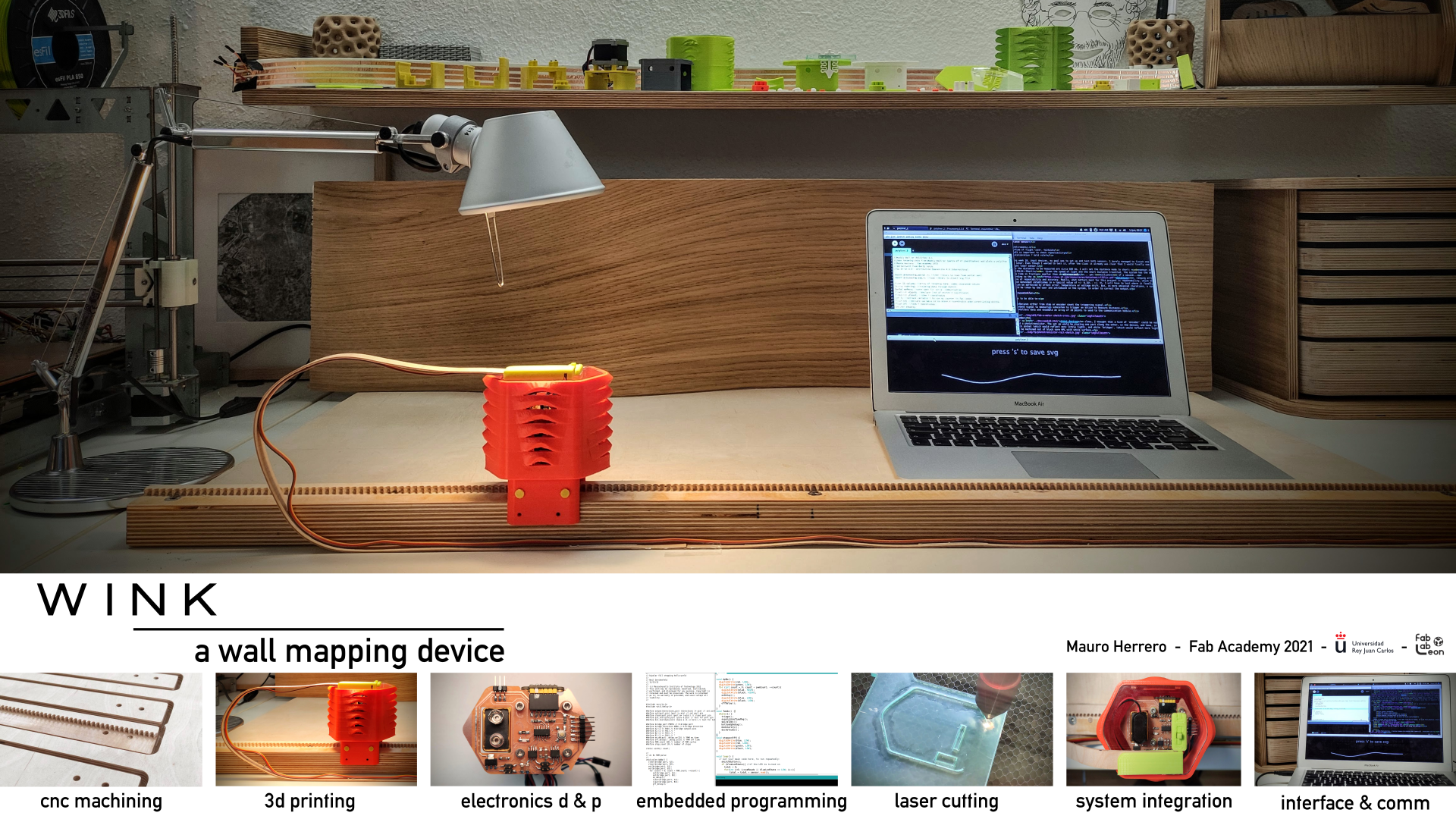
WINK: a wall mapping device
What does it do?
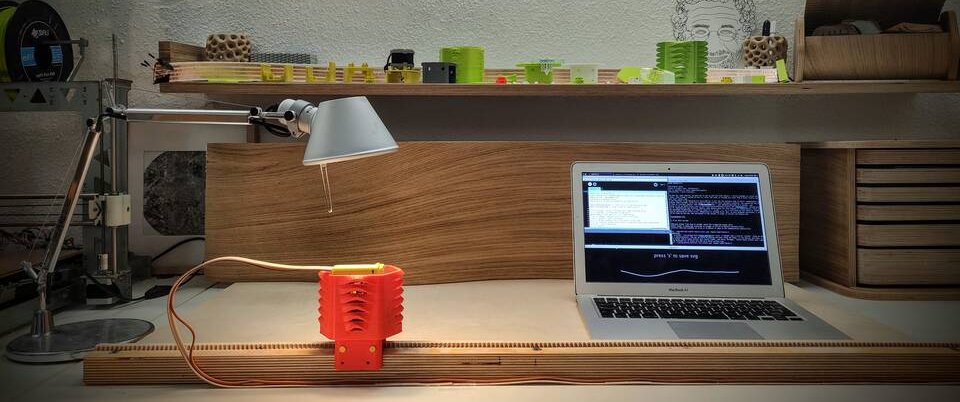
Wink is a small device running along a rail fixed at a distance from an irregular wall. It stops every 40 mm, and then performs then measurements using a ToF sernsor, averages them and sends the output to a Processing program. This program draws then a polyline, and exports it as an svg file at the user request.
The output can then be used to cut a piece to fit the wall that had been measured.
Who's done what beforhand?
The commertial application that might resemble more what I am making is this Leica Disto s-910, combined with the sofware from Cabinet Vision. It is a quite high-end solution, aimed to medium or large contractors, with a price completely out of reach of a hobbyist.
Ivan Sanchez, from Fab Lab Oulu, made in the 2017 cycle thisModular multimeter, integrating also a distance sensor. He wanted to setup an I2C network for the different modules to comunicate, but in the end did not make it work that way.
I also found an attempt to make a Mini Total Station, by Manu Mohan in 2019, in Fab Lab Trivandrum. He used a laser range finder module, since he wanted to measure longer distances, instad of the VL53L1X from the Fab Lab Inventory.
Jens Dyvik, from Fab Lab Fellesverkstedet, has developed several machines, with very interesting axis modules. I will definetly use one of his fabricatable axis modules for the linear motion system in my final project.
What did you design?
This is the list of items that I finally design:
- A test bench, with place for a guide system and a wall, that can be detached.
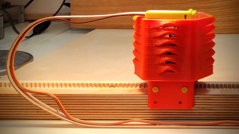
- A carriage, with a stepper motor and room for batteries and electronics.
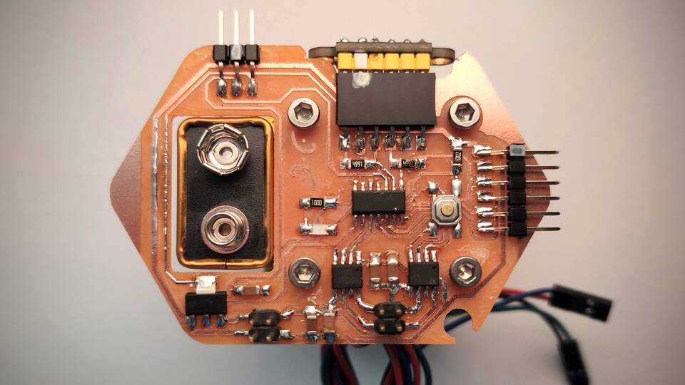
- Circuit board, with a button, LED, bipolar stepper driver and the ToF VL53L1X distance sensor.
- The software to move the device, take measurements and send them to the Processing interface.
- Enclousure for the device.
- An interface to output the data sent by the sensor.
- A cable guidance, with flexible wood.
- A button with a printed spring system, to access the button on the PCB.
What materials and components will be used? Where will they come from?
The test bench is made of 12 mm birch plywood, supplied by Riga Wood.
The carriage and enclousure have been 3d printed, using regular both PLA and PETG Prusament.
All electronic components are in the Fab Lab Inventory. Most of them are sourced by Digikey. But the following were sourced via Aliexpress or Amazon Spain by different vendors:
- Allegro A4953 stepper driver
- VL53L1X time of flight sensor
- L53B 5V 1A voltage regulator
- 4 pin SMD micro button
- Colour LEDs
- Nema 14 bipolar stepper
A more detailed list of the materials used and its quantities can be found in the BOM.
How much did it cost
The total cost to replicate the project is 54.03 Eur. Please note that most of the cost is due to the wood used for the test bench, and for sure there are cheaper alternatives, such as MDF or OSB.
| Item | vendor | quantity | unit price | total |
|---|---|---|---|---|
| Oak veneer, 250x0.6 mm | B. Rincon | 1.00 | 3.14 | 3.14 |
| Flexible wood | Quewood | 1.00 | ||
| Nema 14 0.8A bipolar stepper | StepperOnline | 1.00 | 9.02 | 9.02 |
| AT Tiny 1614 | Digikey | 1.00 | 0.81 | 0.81 |
| A4953 full-bridge driver | Aliexpress | 2.00 | 0.62 | 1.24 |
| VL53L1X ToF sensor | Aliexpress | 1.00 | 5.37 | 5.37 |
| L53B 5V 1A voltage regulator | Aliexpress | 1.00 | 0.17 | 0.17 |
| Colour LED | Aliexpress | 1.00 | 0.02 | 0.02 |
| 4.99k resistor | Digikey | 2.00 | 0.02 | 0.04 |
| 10k resistor | Digikey | 1.00 | 0.02 | 0.02 |
| 1uF capacitor | Digikey | 3.00 | 0.02 | 0.06 |
| 10uF capacitor | Digikey | 2.00 | 0.02 | 0.04 |
| PCB FR1 7x10cm | Amazon | 1.00 | 0.91 | 0.91 |
| SMD button 4x4x1.5mm | Aliexpress | 1.00 | 0.06 | 0.06 |
| SMD 6 pin 2.54 mm female | Aliexpress | 1.00 | 0.48 | 0.48 |
| SMD 6 pin 2.54 mm male | Aliexpress | 1.00 | 0.07 | 0.07 |
| SMD 3 pin 2.54 male | Aliexpress | 1.00 | 0.05 | 0.05 |
| SMD 2x2 2.54 male header | Aliexpress | 2.00 | 0.05 | 0.10 |
| 9v battery connector | Amazon | 1.00 | 0.27 | 0.27 |
| 9V battery | Amazon | 1.00 | 3.49 | 3.49 |
| DIN 912 M3x12 bolt | Amazon | 4.00 | 0.03 | 0.12 |
| DIN 912 M3x35 bolt | Amazon | 4.00 | 0.09 | 0.36 |
| 696zz Bearing 6x15x5 mm | Amazon | 4.00 | 0.37 | 1.48 |
| PLA outlet spoolchange (m) | 3dfils | 12.00 | 0.08 | 0.96 |
| PETG Prusament (m) | Prusa R. | 23.00 | 0.12 | 2.76 |
| Igludur I150 (m) | Igus | 1.05 | 0.25 | 0.26 |
| Insert nut M6x12mm | VerduOnline | 6.00 | 0.05 | 0.28 |
| DIN 7991 M6x30 bolt | VerduOnline | 6.00 | 0.07 | 0.41 |
| 120x60x5mm clear PMMA from scrap bin | Lab scrap bin | 1.00 | ||
| Total: | 54.03 |
In the BOM are not included all materials (mainly PLA) used for testing or non functioning parts, such as copper strips for the cables.
What parts and systems were made?
The test bench was made, including a base with insert nuts, a rail with an integrated rack for the drive system and a curved wall. The curved wall was made glueing several layers of plywood, but it ended up being too low, so I made it taller by using flexible wood and oak veneer as the final surface.
The carriage was designed using Freecad, and 3d printed, including all bolts. The only parts of this subsystem were the 4 696zz bearings added for smoother movement.
The vertical part of the enclousure was inspired by Herzog and DeMeuron Basel Signal Box. It was designed using both Grasshopper and Panelling Tools inside Rhino. It was 3d printed using PETG Prusament.
The top lid of the device was designed in Rhino, to match the vertical walls. It was lasercut from a 5 mm thick clear PMMA found in the scrap bin of my lab.
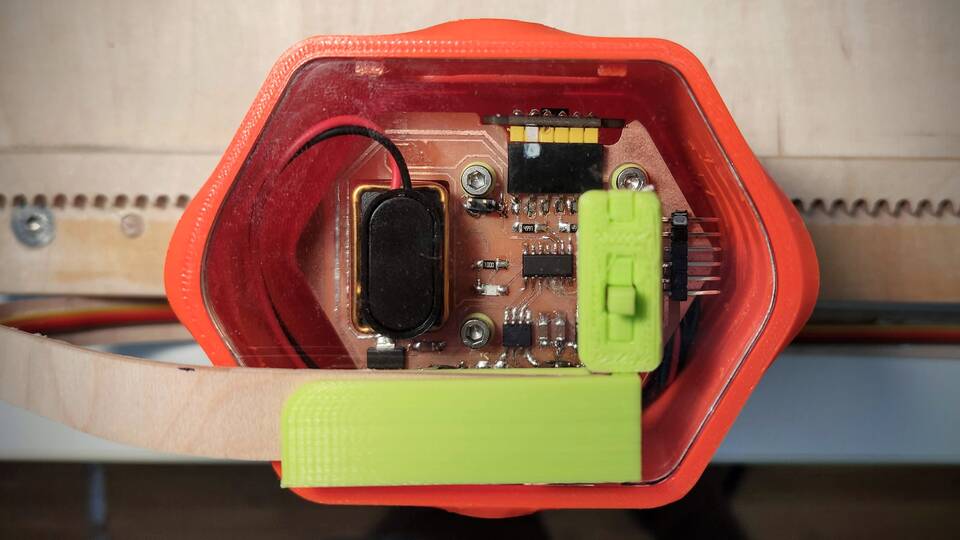
All electronics have been designed using Kicad 5.99. The pcb was milled using mods, it was poulated with components soldering by hand. Instead of using a dedicated driver such as the dedicated DRV8428, I used two A 4953 H-bridges.
The embedded programming was also taylored for this project. I did not use libraries to move the steppers, instead I programmed PWM by software by activating and deactivating corresponding pins. The program included a routine to allow for enough time budget for the ToF sensor to take accurate enogh measurments. In addition to that, it performs ten cycles everytime it stops, and then averages the reading. The microcontroller also sends via serial both the distance travelled and the distance measured. Every pair of values is separated by an end of line.
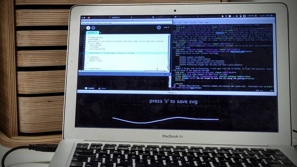
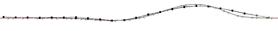
The interface was written using Processing, completely from scracth for this project. It reads the incoming data from serial, assembling two dynamic lists of values, from where, using a loop, the polyline is drawn in real time. After a certain distance has been reached, it allows the user to save an svg file of the output.
What processes were used?
This is the list of processes used:
- Project management; tool used: Taskjuggler.
- 2D design, for some parts of the PCB; tool used: Inkscape.
- 3D design, for test bench, carriage & enclousure; tools used: FreeCad & Rhino.
- Electronics desing, for the board; tool used: Kicad
- CNC path planning; tools used: mods for PCB and Vectric Cut2D for woodwork.
- CNC machining, for test bench, rack and PCB board; Shopbot like CNC machine.
- 3d printing path planning; tool used: Prusa Slic3r.
- 3d printing, for pinion, base carriage & enclousure; tool used: FFF 3d printer
- PCB production; tool used: soldering iron.
- PCB debugging; tools used: multimeter, osciloscope.
- Embedded programming, tools used: Arduino IDE & avrdude.
- Interface programming, tool used: Processing.
- Documenting; tools used: html, css, git and gitlab.
- For just about everithing; tool used: vim.
What questions were answered?
There were quite a few questions anwswered. Even many of them were, even they had not been formulated...
- The Allegro A4953 do not need to run on PWM pins. I did software produced PWM in the 1614, using the output pins as digital pins.
- I did not hav to use PA1 & PA2 as SDA & SCL for IC2. I managed to find a way to solve the board with one sided machining and no 0 omh bridges, so I used PB0 & PB1 directly. The
wire.hlibrary for the ToF I2C communication worked just fine. - About the voltage regulator, I ended up using the 5.0V 1A, not because I needed, but because the pinout worked better in my desing. My board drew less than 100 mA in the regulated side, so my guess is that I could have used the 100 mA... but I am not entirely sure...
- The nema 14 was powerfull enough to drive the carriage without wheels, just sliding. But it also was awfully noisy, so I ended up adding bearings.
- Even the 9v battery could move the stepper, it needed a push to start. So in the end, I connected the system to a 12v power supply.
- The 16k of memory of the t1614 were enough for the program. As a matter of fact, I used about 60% of that capacity. The main reason were both wire.h and VL53L1.h libraries.
- And yes, I was able to finally design, make, program, debug and document in time!!!
What worked? What didn't?
I have to admit that, at some point, I thought nothing was going to work... I was having trouble with just about everything regarding the electronics: the steppers would move erratically, the sensor would send unreadable data, communications was just not working... But with loads of doses of patience, analysis and help from my instructors, I could finally figure all out.
So, WINK starts its cycle when the button is pressed; the LED shines: stars moving 40 mm; takes 10 measurements; averages them; sends them through serial; draws a segment of a polilyne; continues the cycle until the button is pressed again.
Also, the drawn polyline can be saved as an svg file, so a lot has been done!
There are some things that did not work as I expected. First, accuracy: I still have a lot to test, because even overall repeatibility is good, I have still to check how different lighting condicions affect measurement taken. In one of the tests, if the wall was partially illuminated, I would get different results.
Even with a uniformly lit wall, I was getting inaccuracies in some portions of the wall. Part of them happended because the actual wall was adhered to the base with double sided tape, and I checked it was lifting in some part of it. Overall, in one of the portions of the wall, the line was within 2mm tolerance; in the other, it went off by 9 mm. The first case is perfectly fine for the needs of the project. The latter is a bit too much out of tune.
I would also like to use bitwise operations for the stepper cycle, to check if I can get a smoother motor operation.
The 9V battery was not enough to move the device properly. With a 12V battery, or a 11.4V LiPo, I guess that I could solve the problem.
The programming of the stop is not event driven, so, even if it works, some of the cases of when the button is pressed need to be checked out. May be a much easier solution is implement a real switch, so the program starts over everytime the switch is turned on.
How was it evaluated?
Considering the conditions set in week 16, the project is successful!!!
- Upon pressing the button, the device starts the cycle.
- The system takes 10 measurements per stop and averages them.
- The device communicates via serial with a computer.
- The data is recieved in the computer.
- The interface draws a polilyne, which is human readable.
- The interface can save an svg file with the polyline drawn.
- When the device is running, if the button is pressed again, it comes to stop and resets the count.
- The documenting of the project is complete.
What are the implications?
To me, implications of this project are huge. First and foremost, it has opened a door, to be able to face much complex projects that I have to date. I want to keep exploring how motors are controlled. That leads to all kind of machines that can be built.
The most obvious implication of my project is that further research is needed, to get the desired repeatibility. If it not using a ToF sensor, for sure there will be some other way. Once that is answered, a really cool implication would be to attach directly this device to a portable CNC router, so you can fabricate the part in place, right after you have measured the wall. One very interesting possibility is that the device sent the data to Ilan E. Moyer's Shaper Origin, so you can accurately cut the part you just measured.
Now that this is coming to an end, I have mixed feelings. On one hand, I feel terribly sad that it is over; I truly am. But on the other, I am extremely happy for the community I have met. Of course I am amazed of what I have I achieved, but certanly it would not have been the same without the push of every member of this network. My hope is that the end is just the beginning, and soon enough, more joy comes along the way. Thank you all!!!
And I indeed had fun along the journey!!!
Project files
This are the files used in this project. All under a Creative Commons Attribution Share Alike Non Commercial license: