This week I met an interesting chap who has been creating mind blowing Origami for over 15 years. He was interested in embedding electronics in his work to give a different dimension either mechanically or visually to his work. For this I thought using the ATTINY 85 would be ideal for its size and then within a network, different parts of an installation could be controlled via a Pauduino.
This would require I2C communication, a two wire connection that can link multiple devices in a Master-Slave relationship. The two wires are called SCL (the clock line - controlled by the master device) and SDA (bi-directional data line). The same Vcc is required for all the chips, so my connections will effectivley be a 4 wire connection with the two data pins, a Vcc and ground. It is also important to pull up the SCL and SDA pins, I used 10k resistors for this.
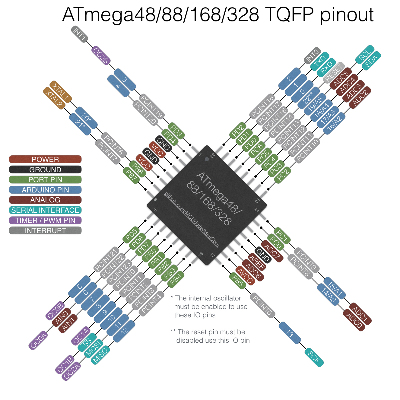
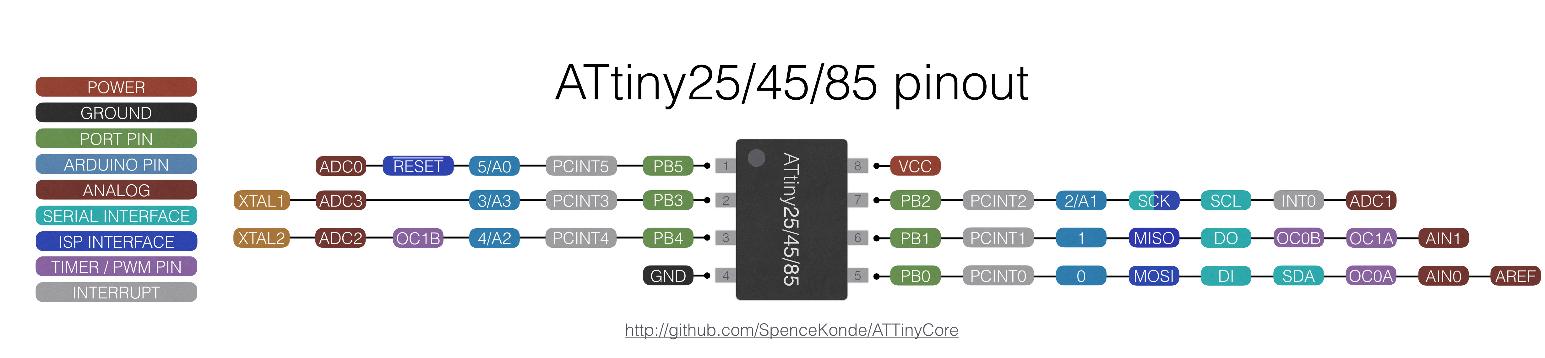
The AT MEGA 368 P-AU has I2C interface built in, however the ATTINY 85 does not. The 85 has Universal Serial Interface (USI), but this can be used to facilitate I2C and SPI communication. Fortunately there are libraries available to handle this; TinyWireS is the library I will be using.
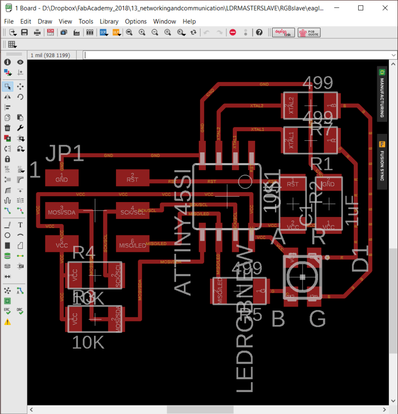
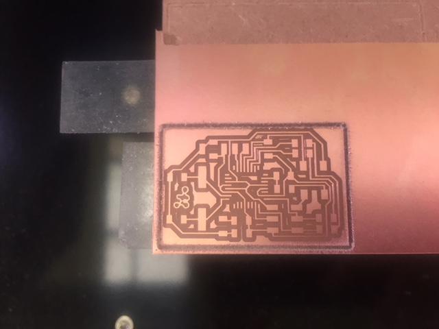
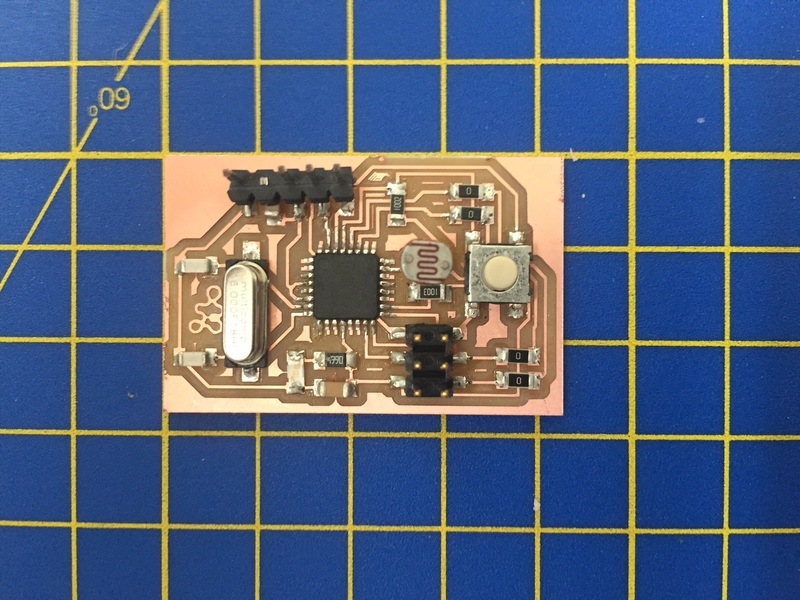
But first to mill the boards. I created a master 368P-AU with an LDR and a Tiny85 with a RGB LED. The aim of this is to control the intensity and colour of the RGBLED on multiple 'slaves' based on the light levels around the 'master'
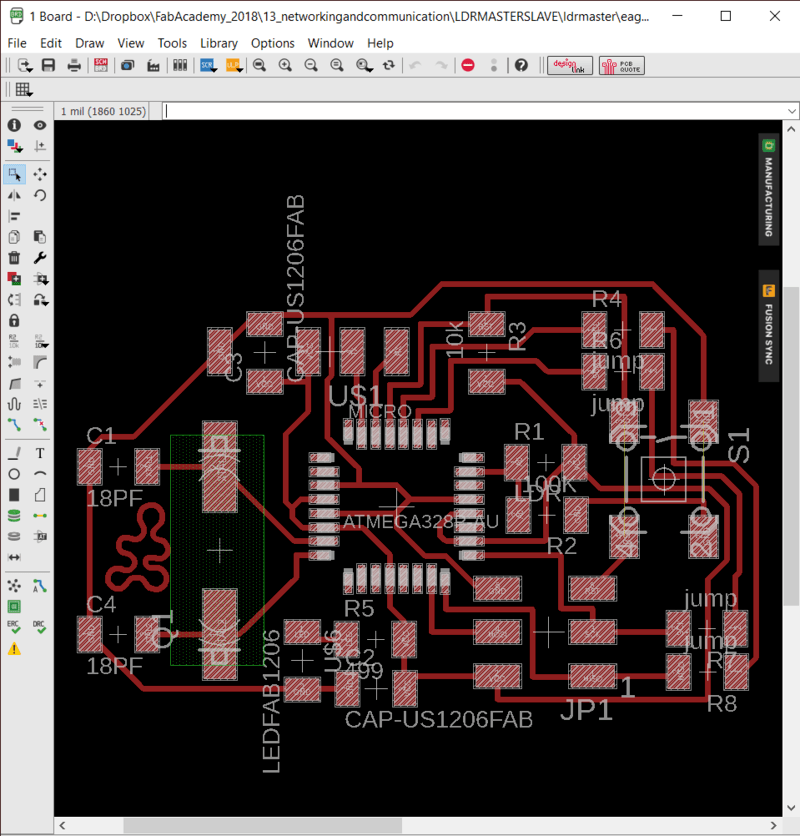
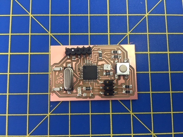
I populated my master board. I ended up changing the resistor a few times and then replacing my LDR with a through hole componenet as I wasn't getting the resolution I was hoping for with the LDR initially.
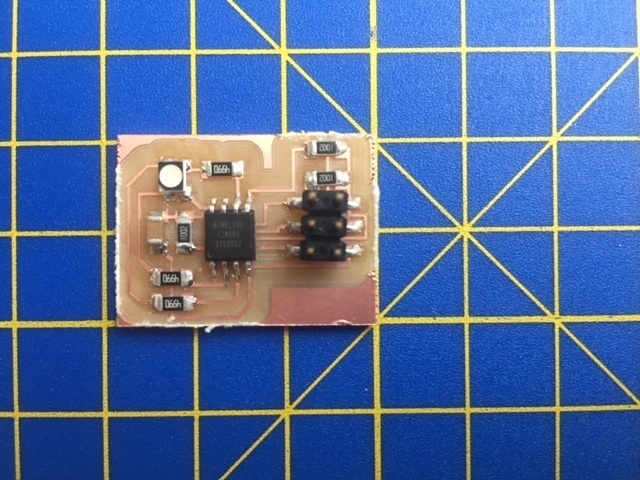
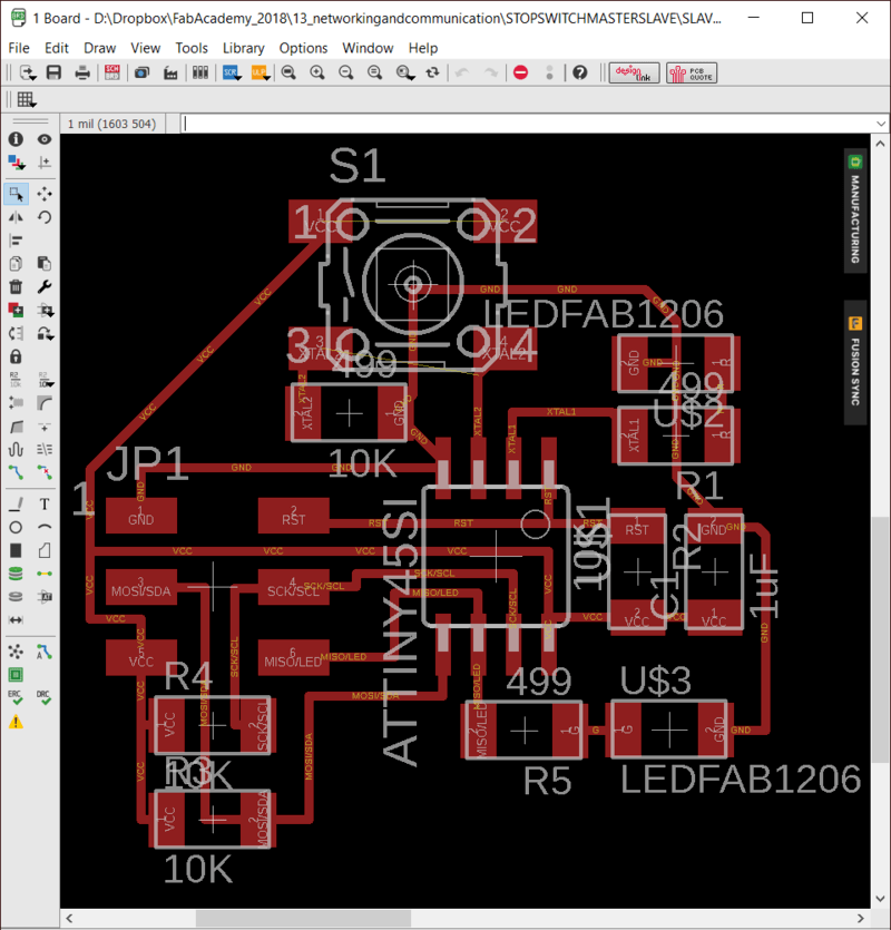
Next was to to create my 'slave' board. I did this using a RGBLED. As I was using an ATTINY 85, the pins I was using was limited and the Cree RGBLED I was using used up 3 pins immediately. I needed two for the SCL and SDA and then reset (some good info on using the reset pin as an I/O here), GND and Vcc were already taken. So for this doubled up on the pins for programming with some I needed for the LED. This was actually quite nice in the end as my board flickered blue when loading a new program as it was connected to MISO.
It is worth noting that the CREE RGBLED has a common ANODE, rather than common cathode. This means the anode is connected to Vcc and the 3 pins controlling the 3 LEDs are connected to the 3 pins via their own resistors. I used 499Ohm, but according to the datasheet I could go as low as 250Ohm. For the stock in the lab this would have required 2 1000Ohm and 1 499Ohm in parallel taking up vital space. The LED was still blindingly bright with the 499, so for testing purposes I would recommend even higher rated resistors.
As these LED's are controlled from the cathode side, when you want the LED to be ON you still have the pins as 'OUTPUT', but you output 'analogwrite(LED, 0)' or 'digitalWrite(LED, LOW)'.
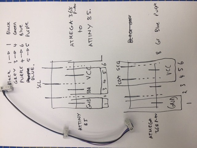
I also avoided putting in extra pins for the SDA/SCL as these are both on my programming pins (MOSI and SCK respectivley) and so I just used the 6 pin header to connect master and slave. What I found out however was I connected the ATMEGA368P-AU SDA/SCL differently on the programming pins. This led to a lot of frustration and messing about with wires everytime I needed to program and re-hook up the master-slave, so I created a custom 6 pin header to make life easier.
Finally I attached 2 female pins on top of my decoupling capacitor to power the board while programing.
I succesfully soldered my board and managed to get a blink test working. (from Adafruit)
I had a lot of trouble programming these boards using the Wire.h and TinyWire.h libraries. The Wire.h is widely used for obvious reasons, but the TinyWire.h library is reported as being a bit buggy and less widely used, so I could find less examples. I could get the test files to work and a few example files from previous students, but these all seemed to have the data going from the SLave to the Master.
here is another link that has info on the TinyWireS.h library.This was good as I could see both boards were working and I was capable of I2C communication, however I needed information going the other way with my LDR controlling my RGB LED.
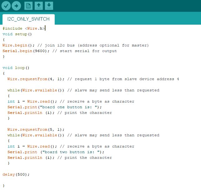
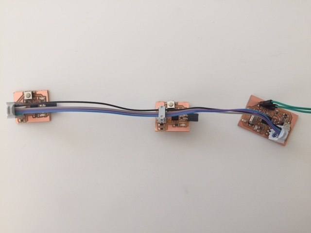
This led me to thinking that it actually makes a lot of sense to have the information going from MASTER to SlAVE, with this it is possible to have many sensors connected to only on pin on the MASTER board. For my final roject I will require at least one limit switch st every axis to set the zero and stop the robot crashing into itself. Instead of taking up 7+ pins for each switch I can create and I2C circuit to control all of them using just the SDA and SCL pins. So I took a quick detour as I wasnt getting very far... see below to find the new boards I made with multiple slave switches telling the Pauduino wether they were on or off.
After my sojourn into limit switches I was able to come back to understanding more about the TinyWireS.h library. I managed to find an example by Karsten Nebe which I managed to get working with the most satisfying of blink tests
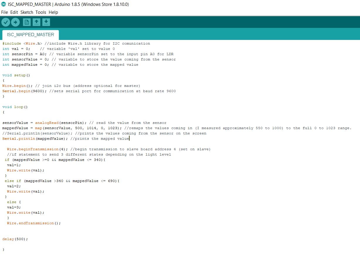
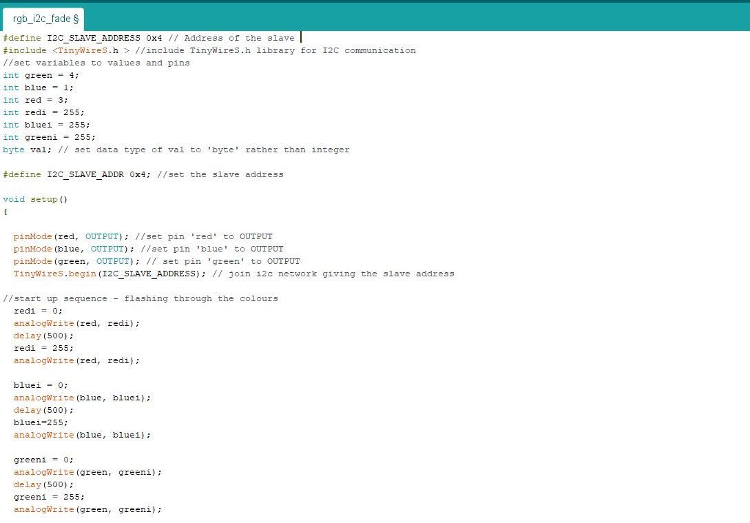
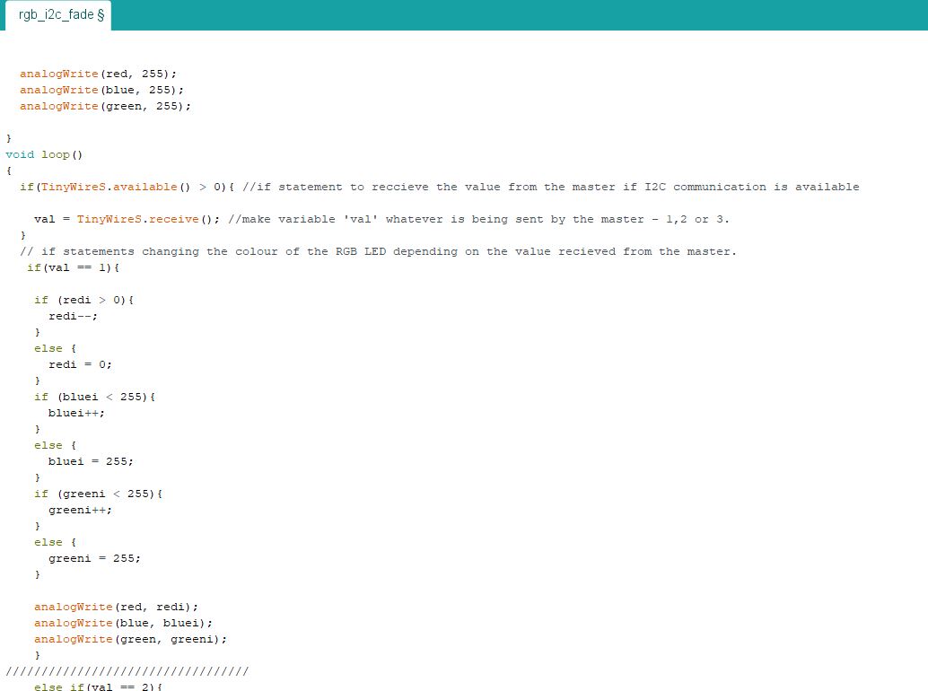
After I spent some time coding the master and slave to give 3 different RGB setting sbased on light intensity with a fade involved as well between the 3 different states.
See below for the commented code for the master LDR and slave RGB.
Limit Switch I2C
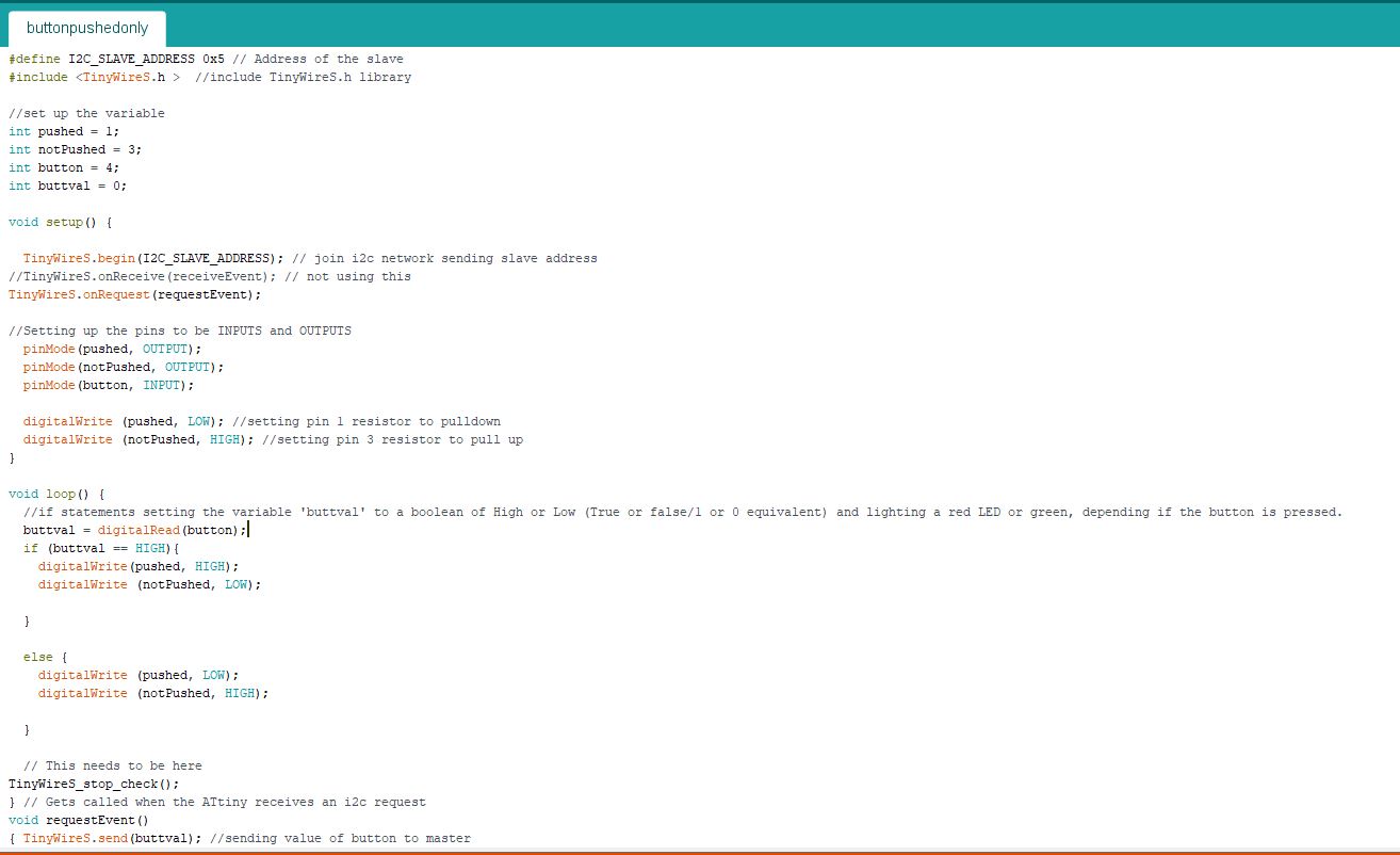
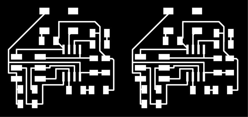
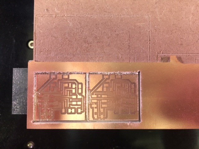
As stated above, I will need many limit switches, at least on for each axis of my robotic arm. To avoid using countless pins I can connect these all in a network using I2C. I modified my RGBSLAVE board to create a board with a switch and 2 LEDs to indicate if the button was pressed or not. I also edited the files so I could mill multiple boards at the same time which will save on wasted time changing tools.

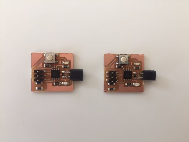
I used the same example codes as before and hey were working succesfully. I then programed the slaves to send back an 'pressed' or 'notpressed' value depending on the status of the button and have the LEDs on the slave to switch on/off depending on wheather the switch was pressed.