4. Computer controlled cutting
Assignment
Group assignment
- Characterize your laser cutter’s focus, power, speed, rate, kerf, and joint clearance.
Individual assignment
- Cut something on the vinyl cutter
- Design, laser-cut, and document a parametric press-fit construction kit, accounting for the laser cutter kerf, which can be assembled in multiple ways.
Laser cutting
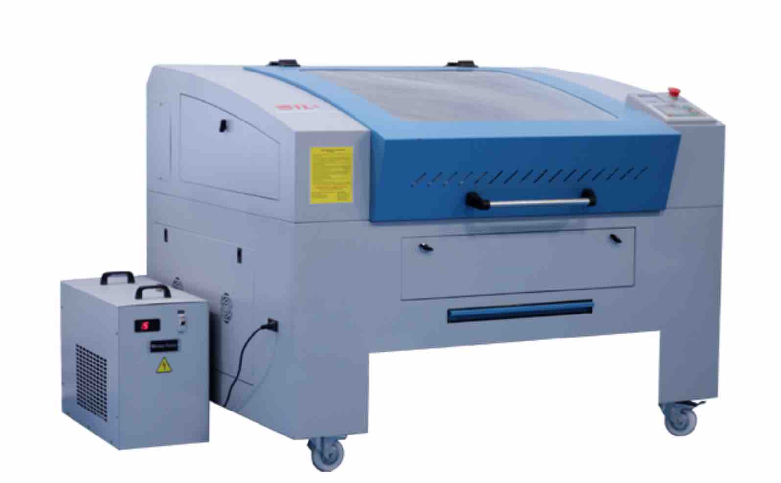
The group assignment was to characterize our laser cutter so, we started with it. In our lab, we have SIL brand laser cutter.
Essential parts of laser cutter
- Laser tube- It is the laser diode from which laser emits. In our machine, we had CO2 laser tube.
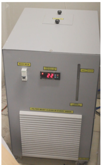
- Chiller- For maintaining water flow in the laser tube and to maintain the temperature of the laser tube within safe limits.
- Reflectors- To deflect the laser beam from the origin point to the destination. It has an assembly of 3 mirrors placed at 45 degrees each.
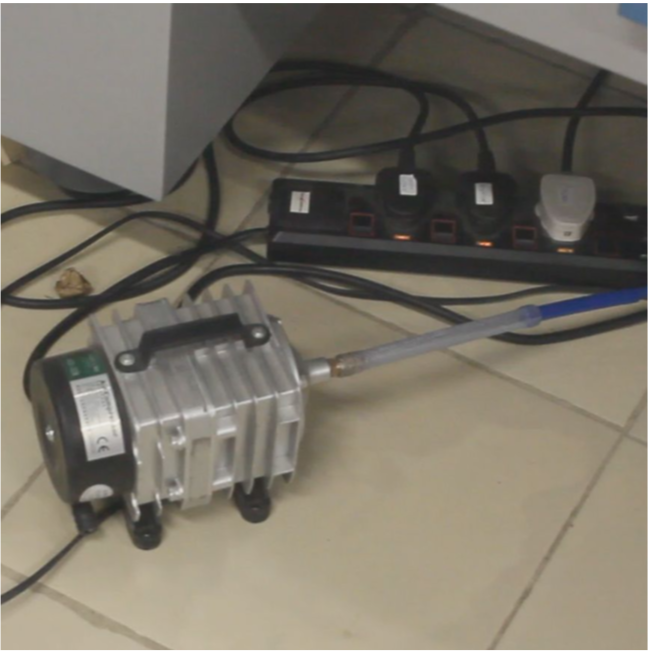
- Blower- To pump the air from the nozzle of the laser head. It helps in extinguishing flame generated due to heat and to blow off the ash and dust particles from the cutting path.
- Controller- To control/operate the machine manually.
Safety precuations
- Turn on the laser only when you are all set for cutting. keep the laser turned off while doing other settings.
- Always keep the hatch closed while cutting/etching.
- Don’t see the laser beam with naked eyes.
- Turn On the laser only when the temperature of chiller is below 23-degree Celsius.
- Don’t leave the machine unattended when it is running.
- Make ensure that exhaust is running when you are operating laser cutter.
Powering up the machine
- Turn on the main power source.
- Turn on the chiller
- wait for the temperature to come down below 23-degree Celsius.
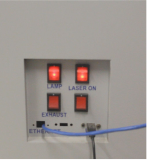
- Turn on the main switch of the machine (at the left side of the laser cutter).
- Turn on the lamp switch(at the right side of the machine.
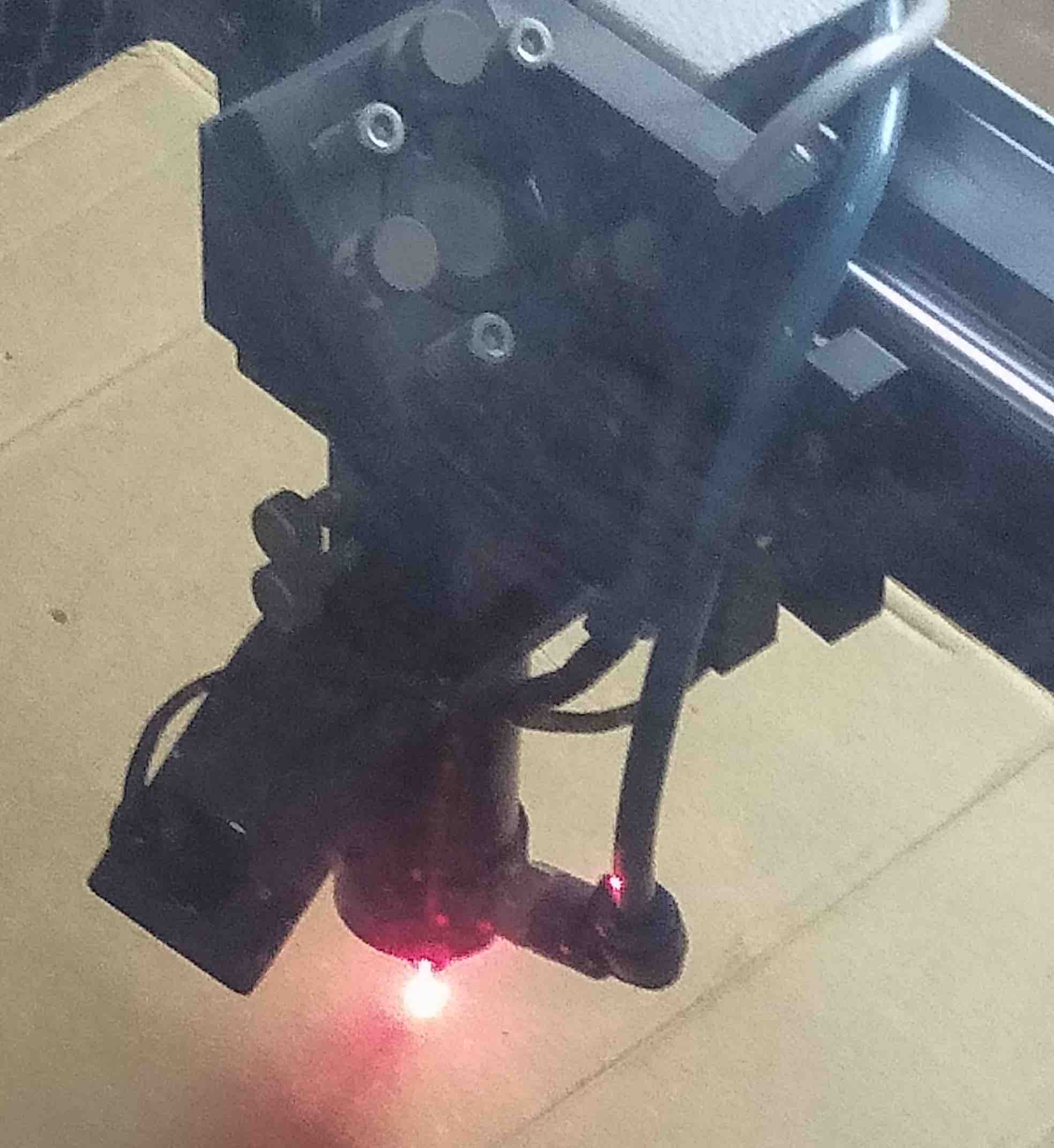
- Set the focus, by pressing Z/U button on the controller–> highlight ‘Z-axis’ option and move the bed up/down using left/right arrow keys. Adjust the Z-axis in a way that the two red dots perfectly coincide with each other to form one single red dot.
- Set the origin, using up/down and left/right arrow keys on the controller and press ‘origin’ button.
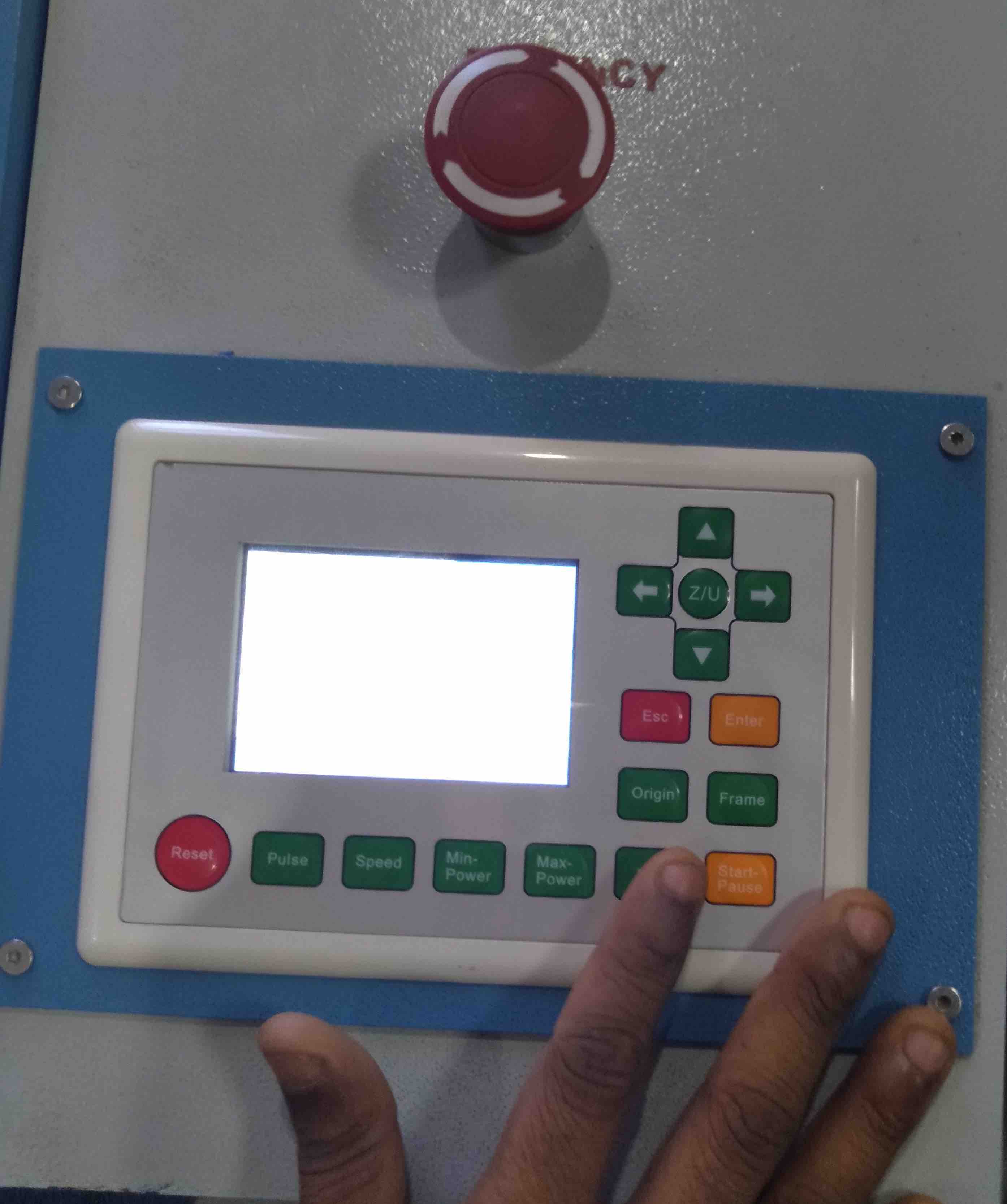
- Turn on the laser and start cutting.
Tests
Materials tested
- Acrylic(2mm)
- Cardboard(2 and 3mm)
- MDF(2mm)
Speed and power test
- For cutting/etching, the most important thing to focus on is cutting speed and laser power.
- Generally, cutting is done at slow speed and high power. For etching high speed and low power is used.
- We tried to cut/etch cardboard at various speed and power combinations.
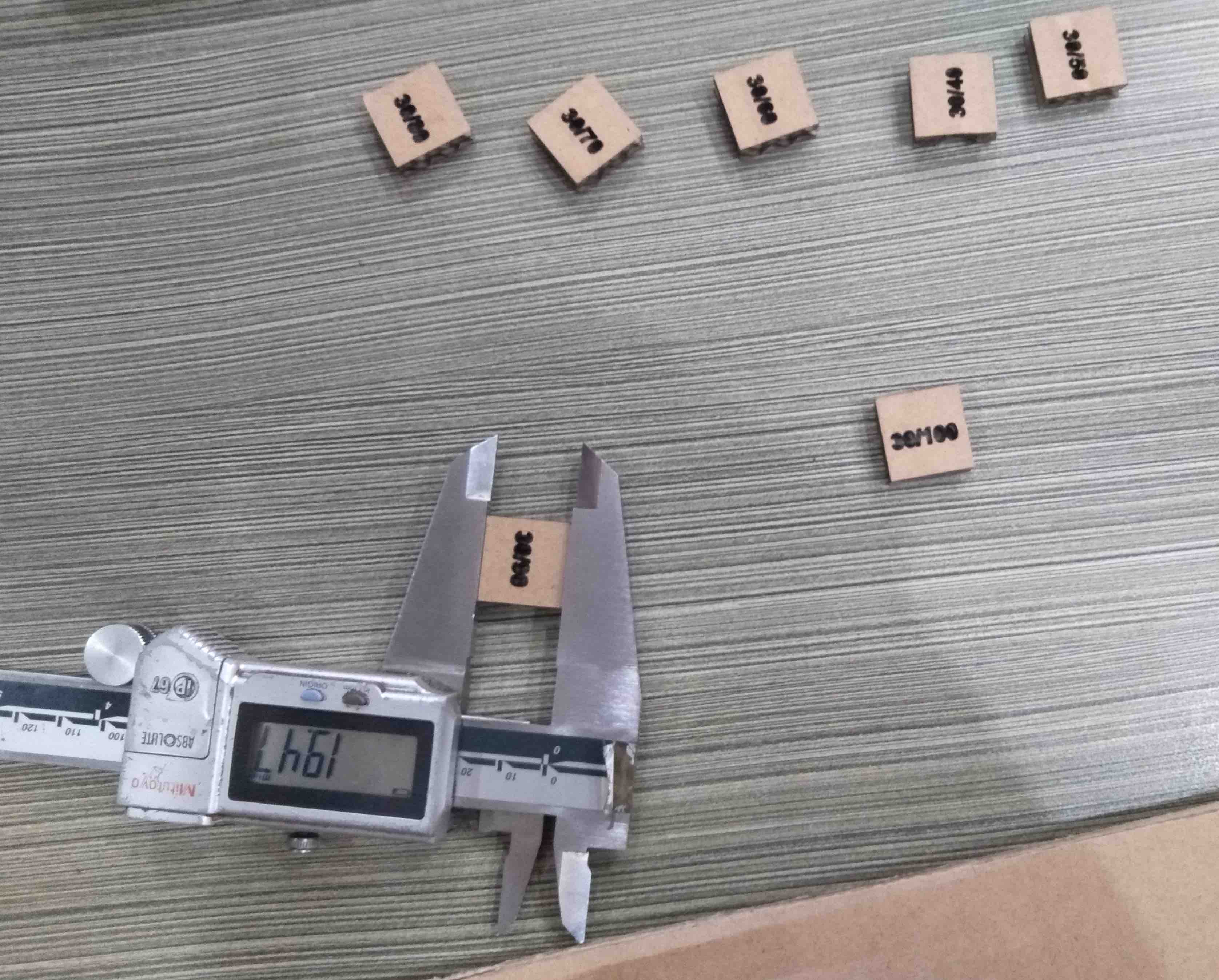
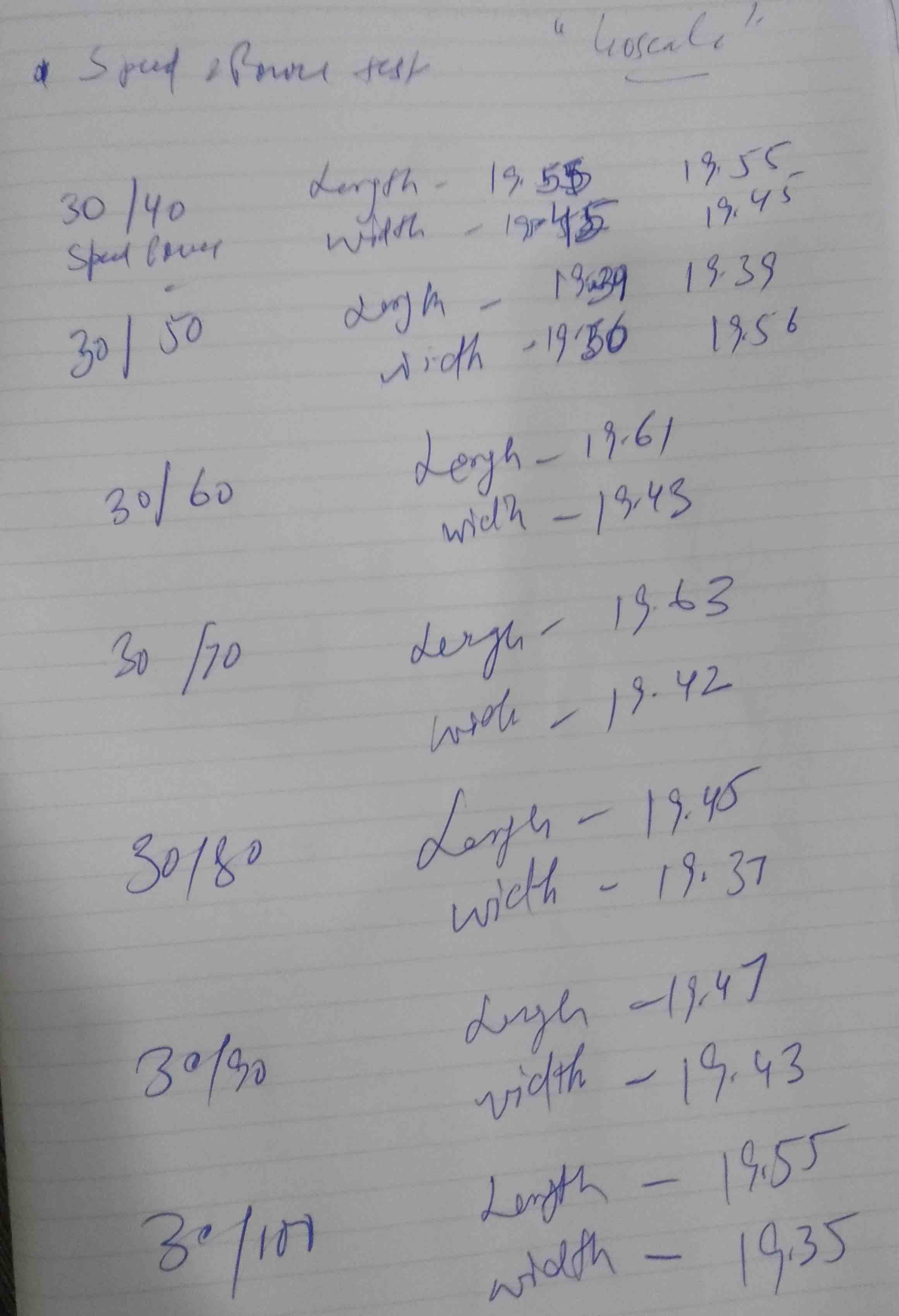
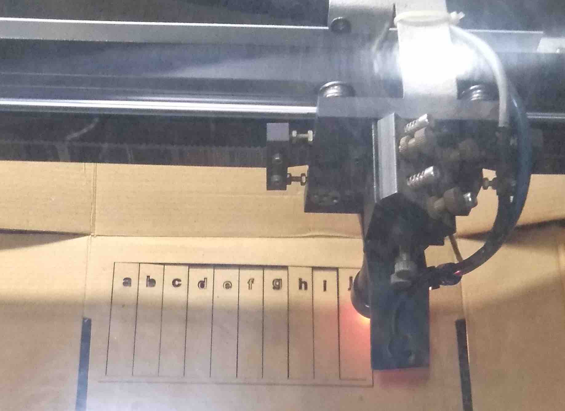
Cutting test
- We cut out a grid of squares with each square cut at varying speed (30 to 300 mm/sec) and power (10 to 100 percent) ranges.
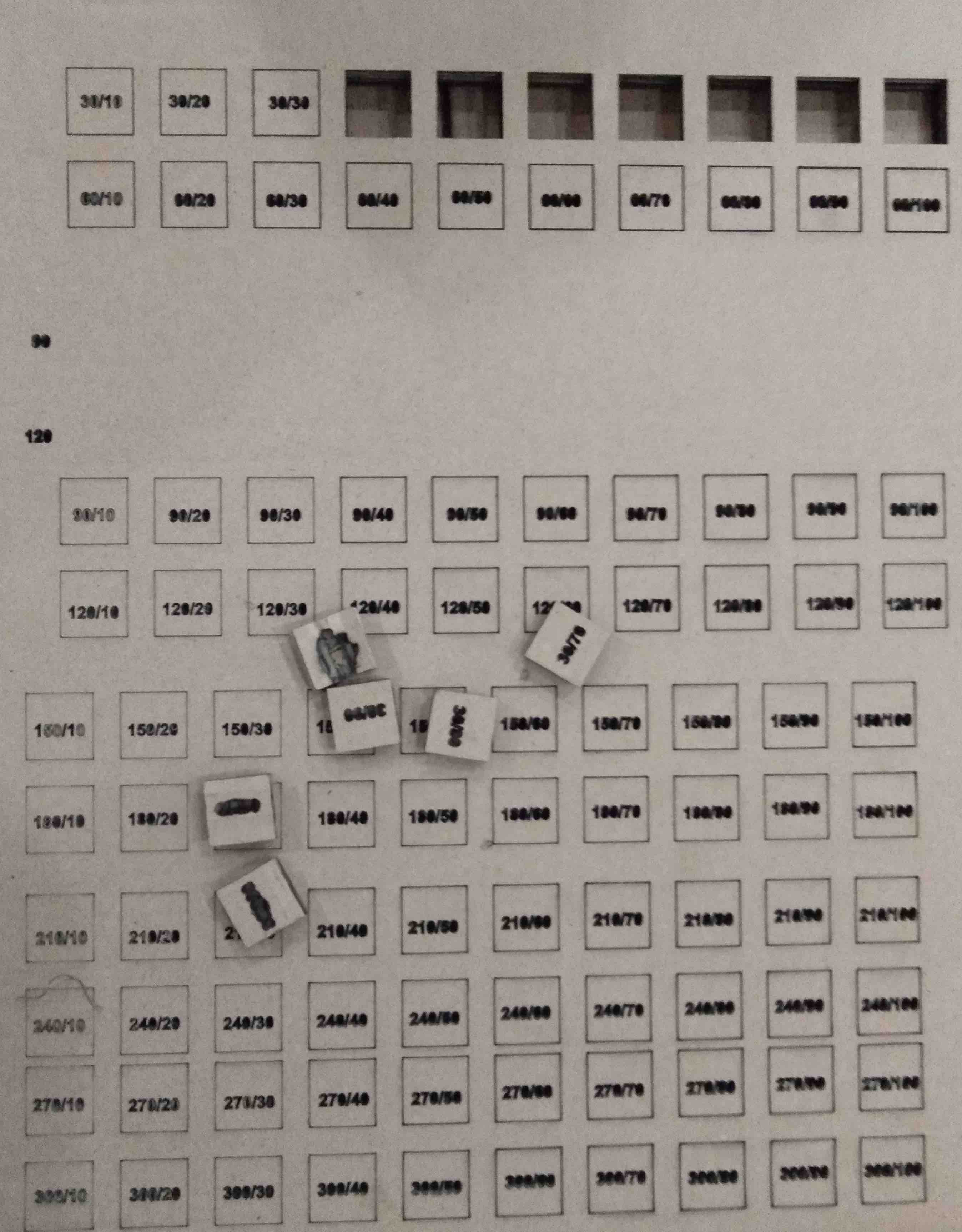
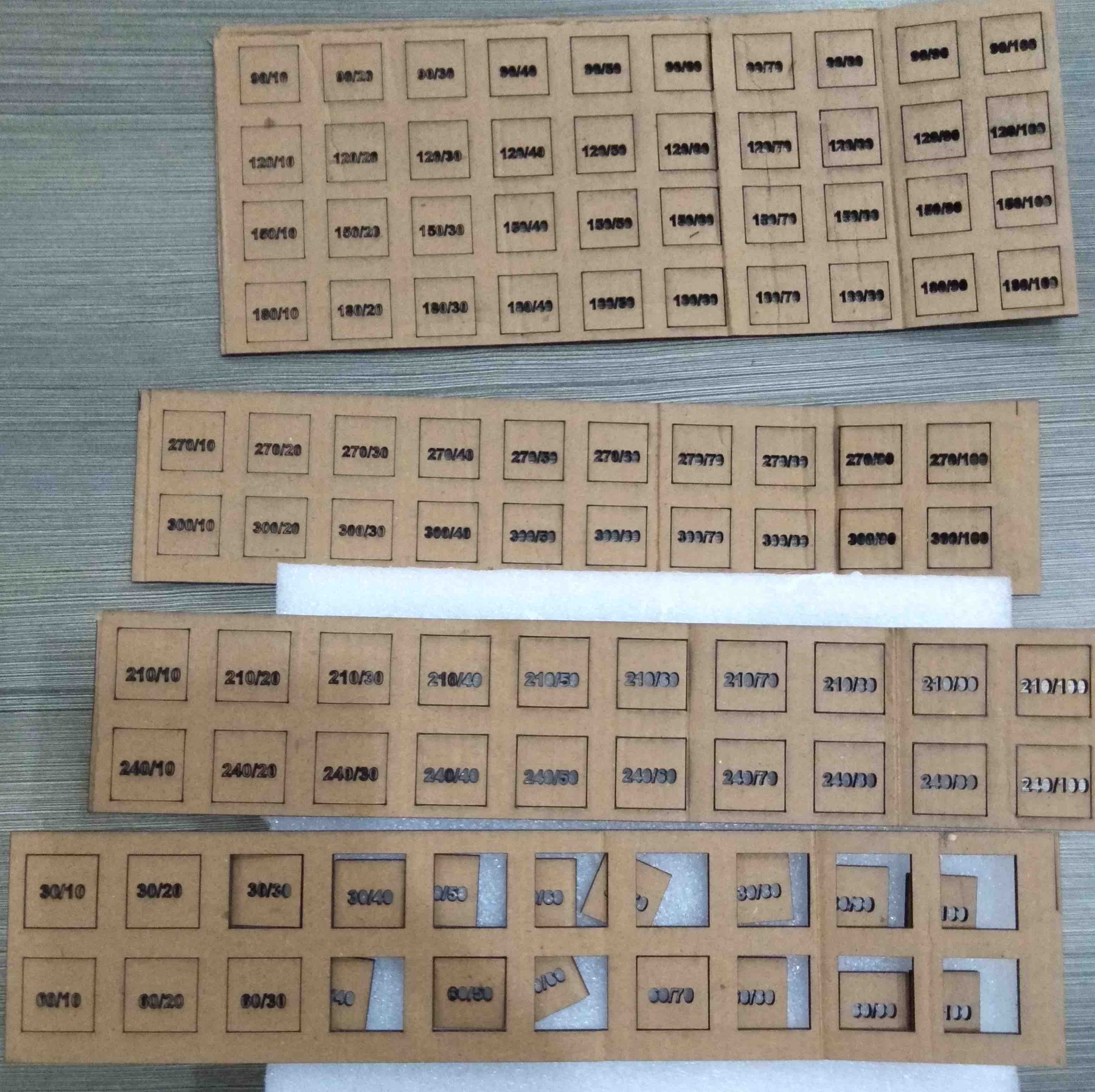
- The 2mm cardboard was cut at a speed of 30mm/sec and 30% laser power.
- We wanted to etch the numbers but forgot to change the layer for etching.
- Also, we didn’t get the exact dimension which we set in the design. So it’s important to set offset the dimensions according to the kerf.
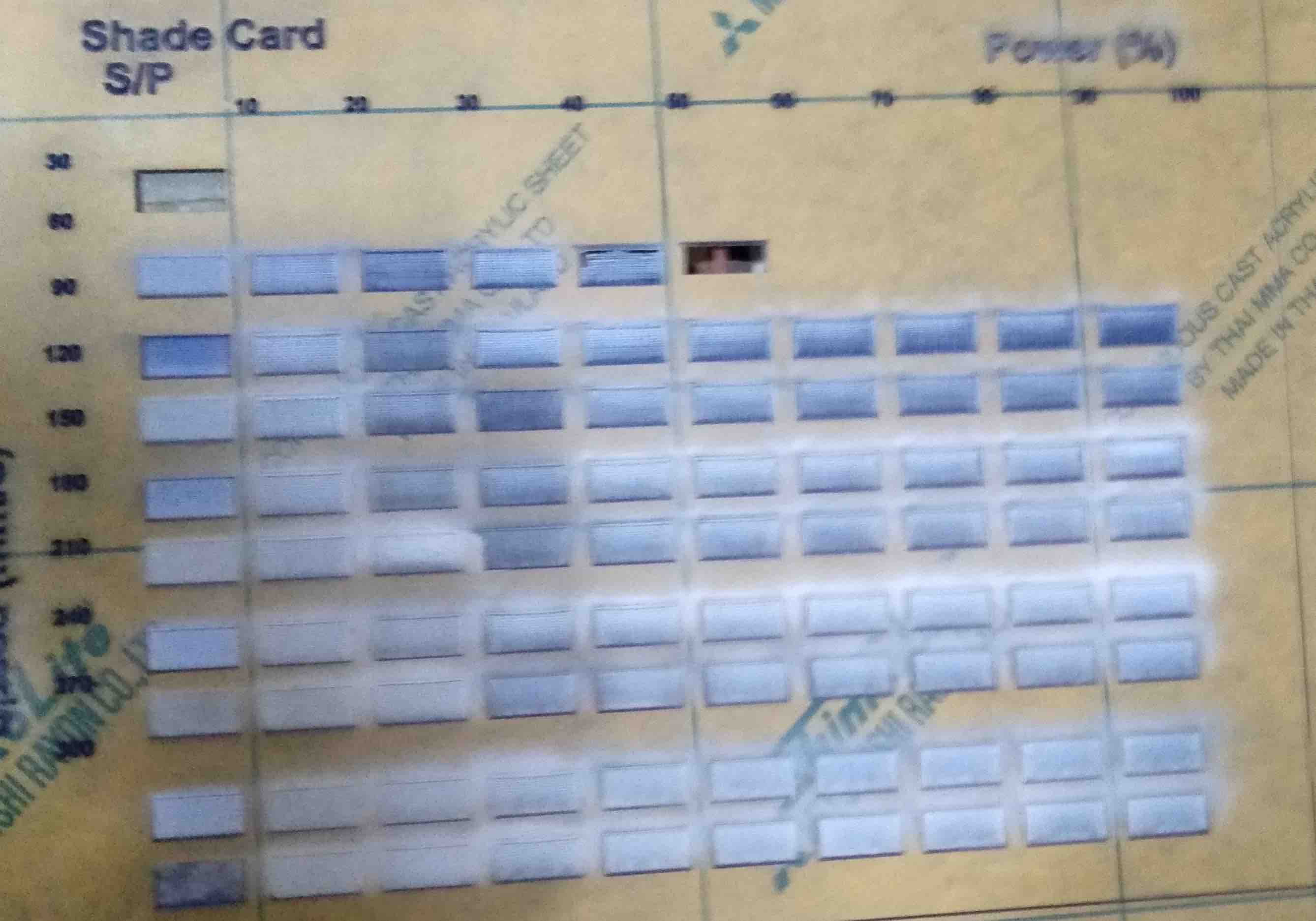
Etching test
- We again created a matrix of rectangles to check various settings for etching.
- This test was performed to check the depth of engraving on acrylic.
Comb test
- This test is important to calculate the slot width for proper press-fit of the components.
- This time we tested on MDF of 2mm thickness.
- we created a comb with different slot size and try to fit it with the material through which we made it.
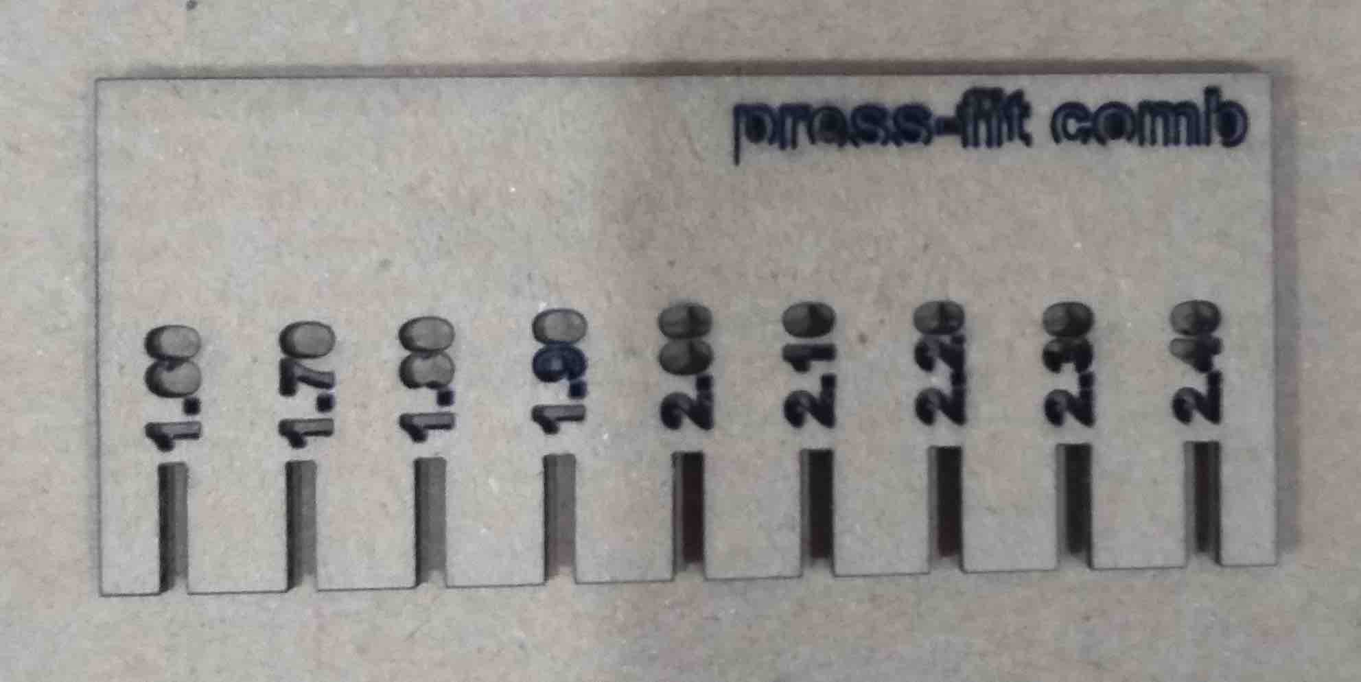
We found that for the MDF of thickness 2 mm we had a good fit for 1.8 mm slot in the comb.
Kerf test
In the laser cutting machine, the materials cut by the heat generated by the laser beam. It means laser burns away some portion of the material, though it is not too much but it matters when you want precise cutting dimensions like for press fit. It ranges from 0.08-1mm depending on the material and cutting settings.
For Measuring the kerf, we made 10 cuts within a rectangle and the shifted all the cuts to one side, then measured the gap, and then divided the gap by 10.
On measuring, we found that we lost 3mm of the materials. so, the kerf in our case is 3mm/10 = 0.03mm.
Press-fit kit
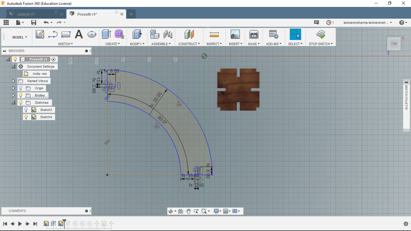
For designing this kit, I used Fusion360, which we learned/practiced in the previous week.
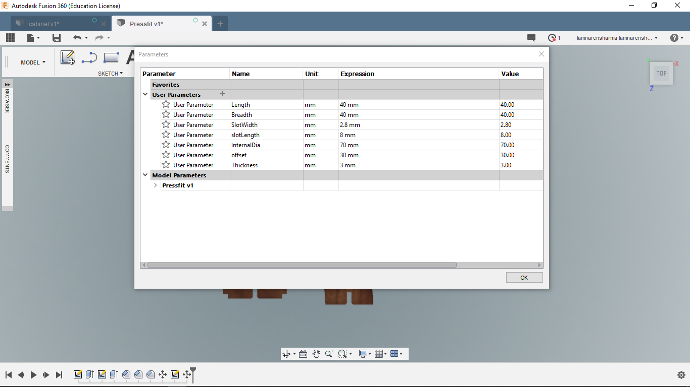
Designing steps
- Set parameters.
- Draw connectors sketch using rectangle and line tools.
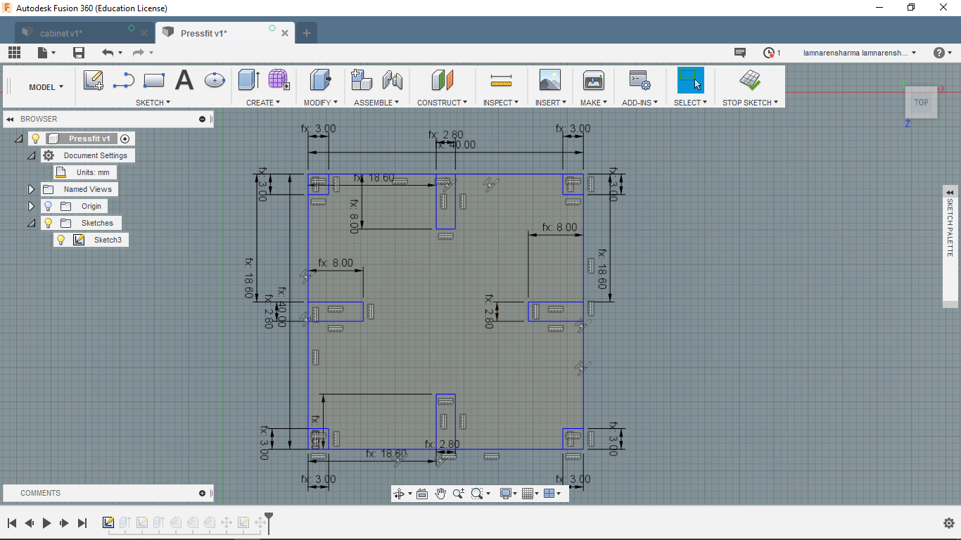
- Extrude to the thickness of the material.
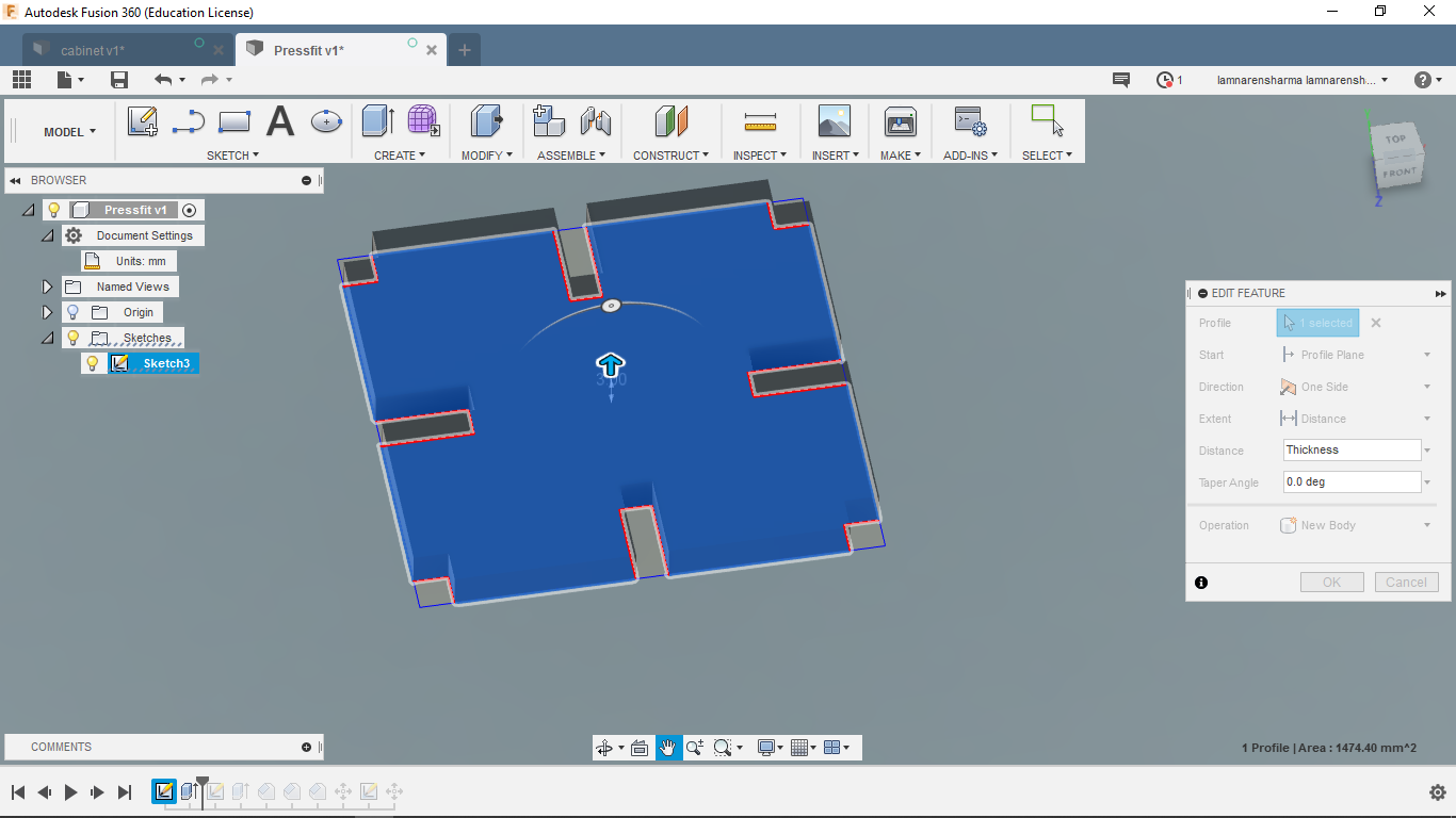
- Again, Draw a sketch of the main part. For this, I selected arc and line tools. Then, extrude it.
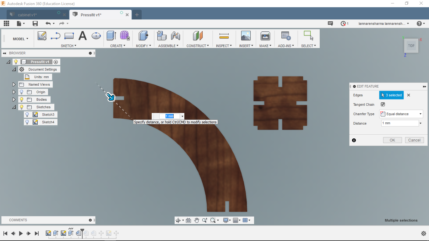
- Chamfer the corners of the slots at insertion points.
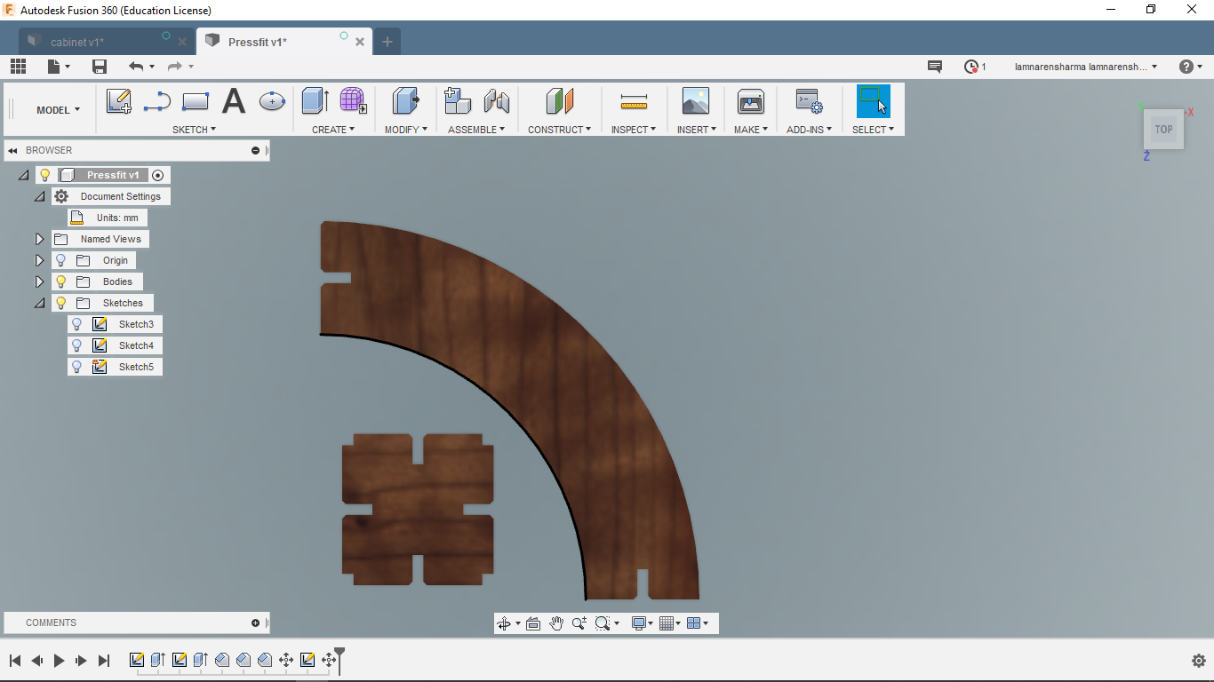
- Right click on the sketch and save as dxf.
Click here to downlod the 3D model of press-fit construction kit.
Click here to download vector file of the press-fit constrution kit.
Laser cutting
- Download RD works software for setting speed, power and cutting modes.
- Import you dxf files in the RD works.
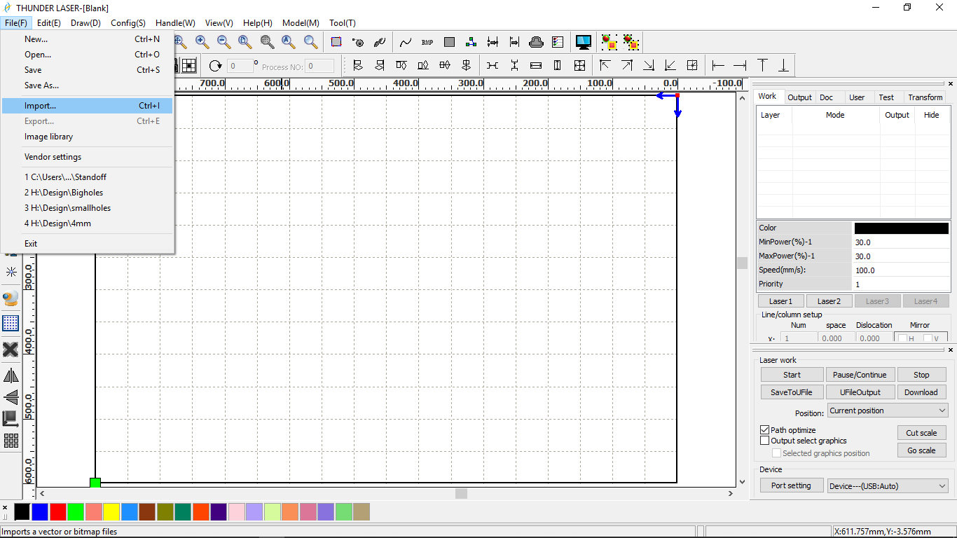
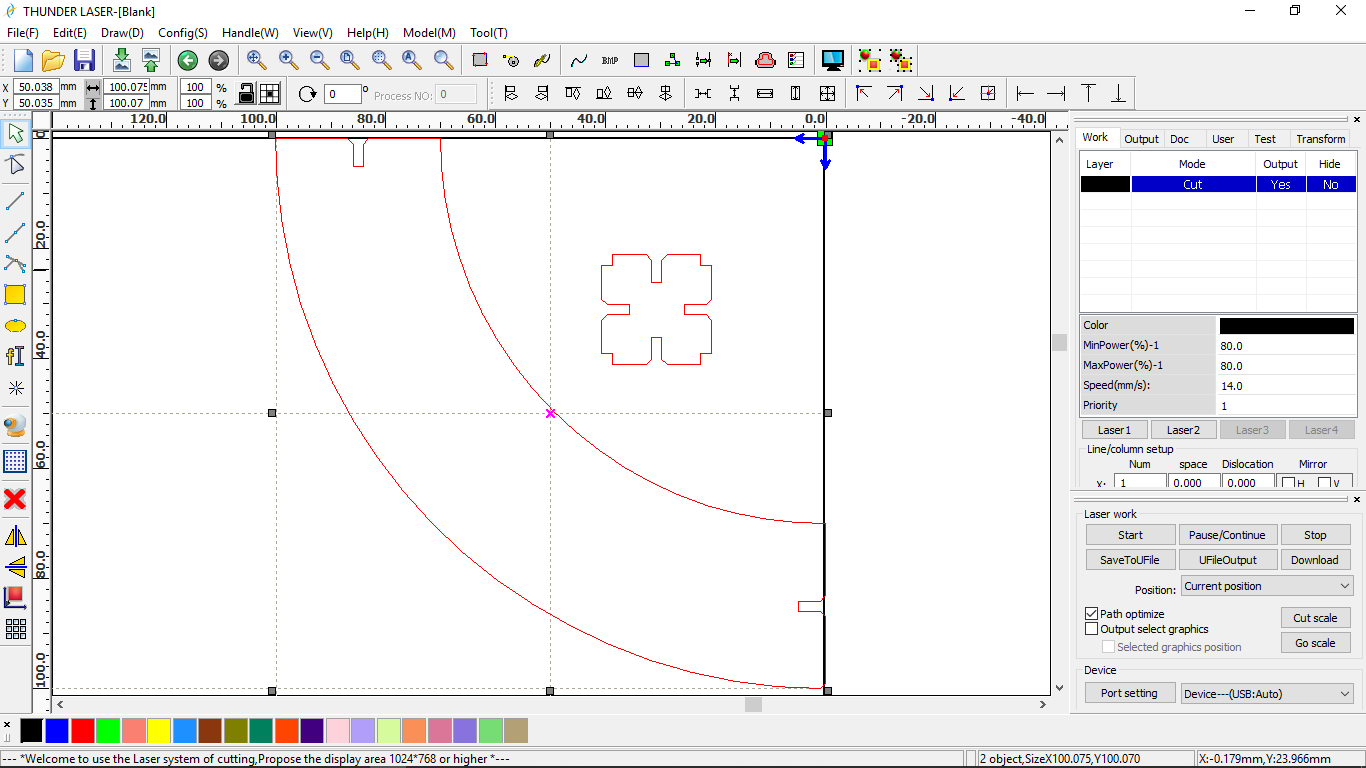
- Copy the required no. of parts and align them to minimize the waste.
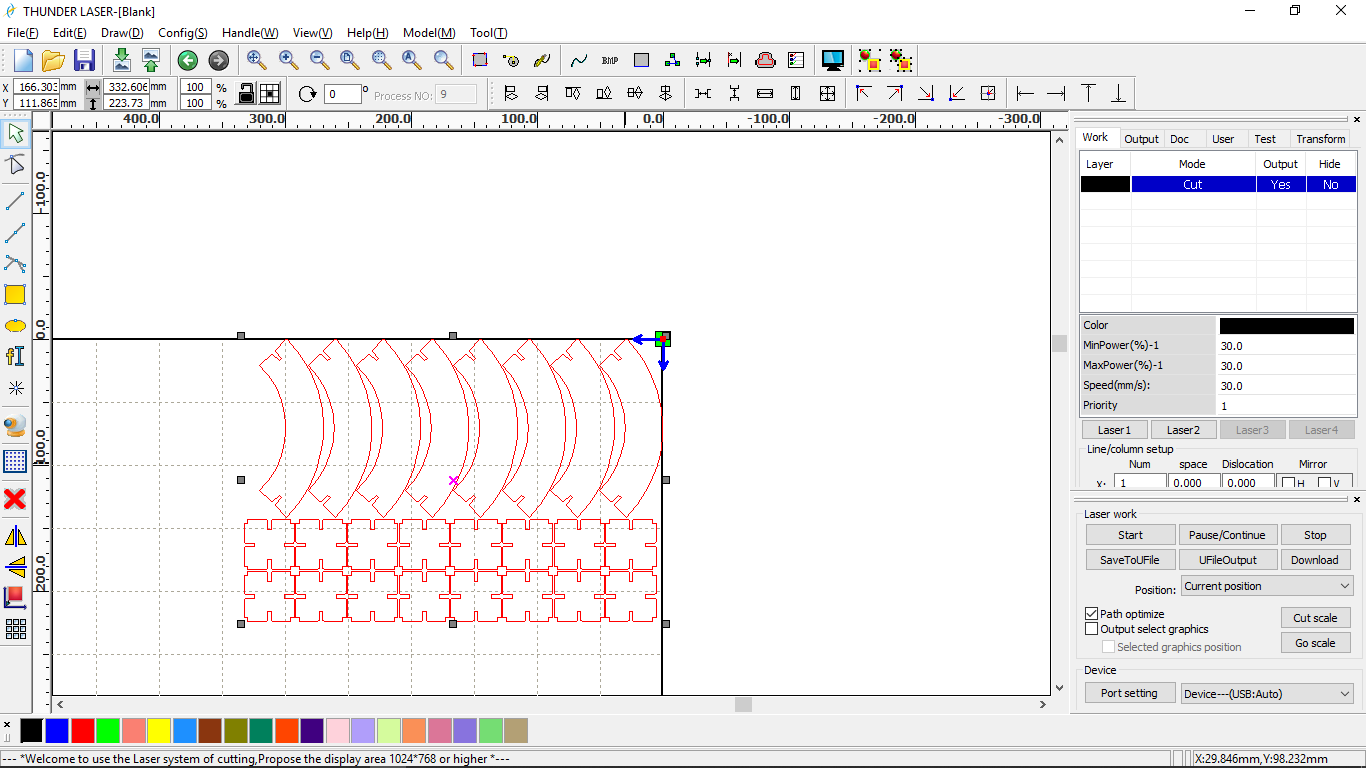
- Open layer settings, and feed the settings. I used 30mm/sec speed and 30% laser power for cutting the 3mm cardboard. Select cut as the processing mode.
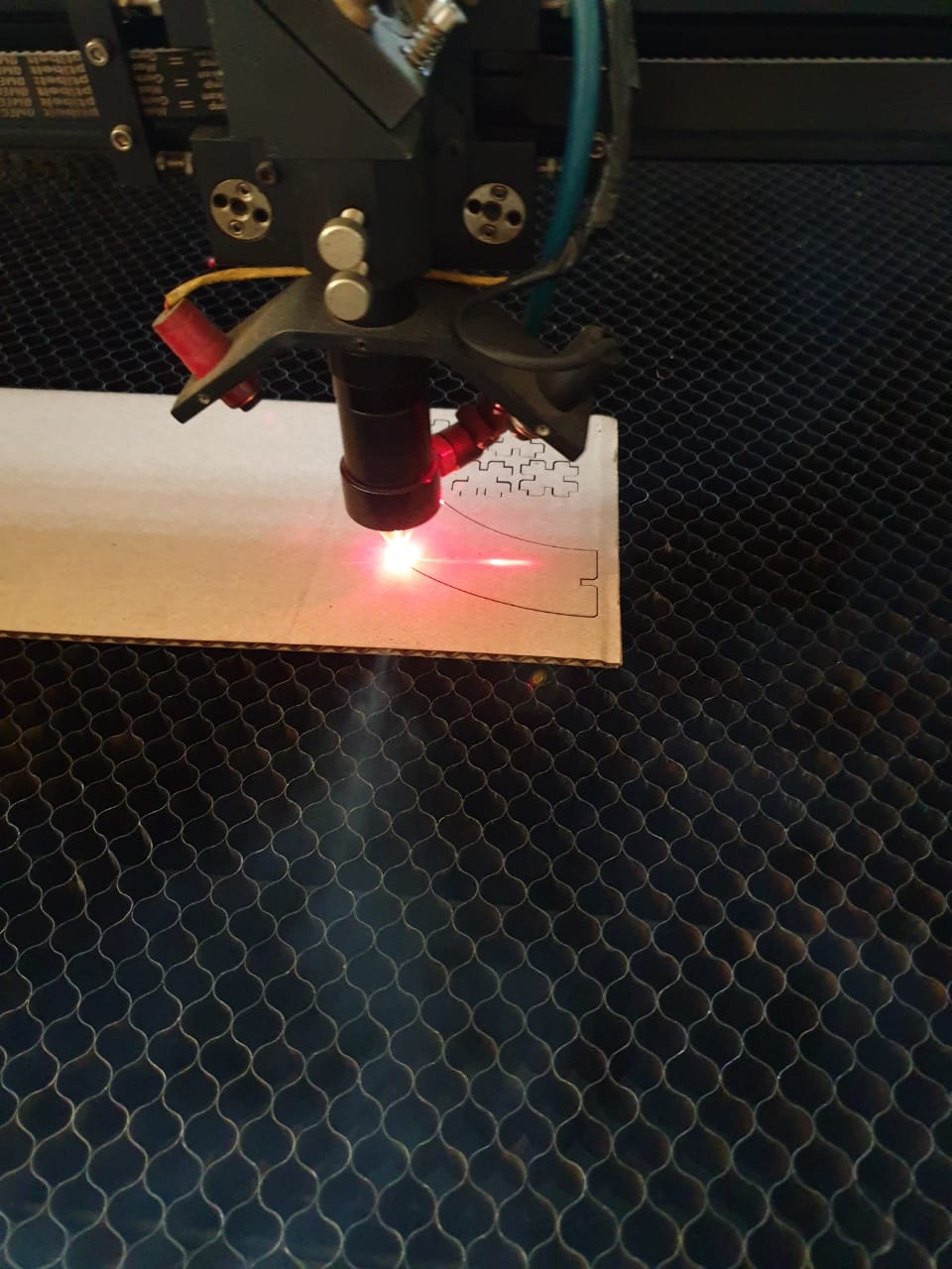
- Connect the machine to the laptop using the USB wire.
- Set the origin.
- Check the cutting parameter by clicking “Go scale” option.
- Click on “Start”
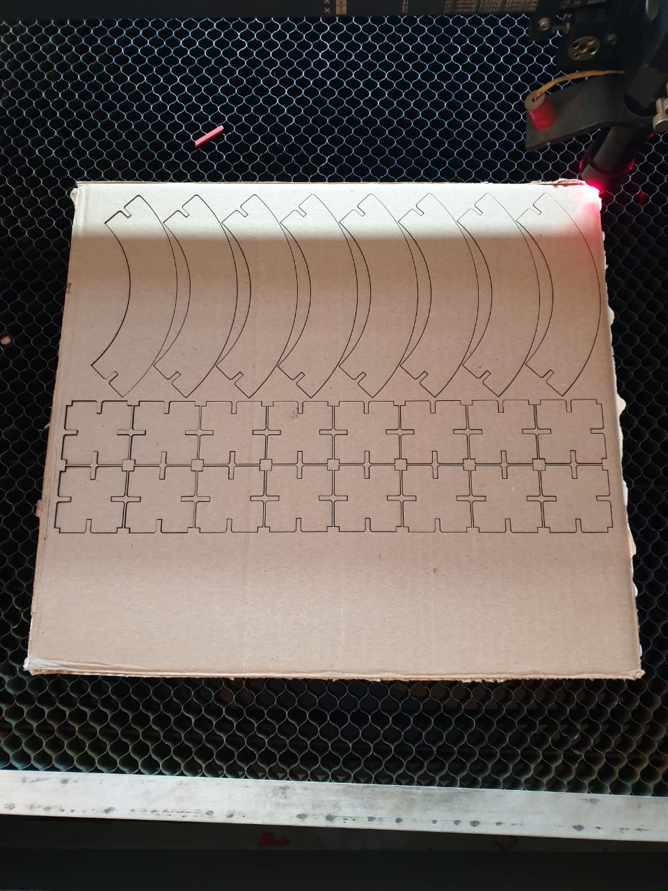
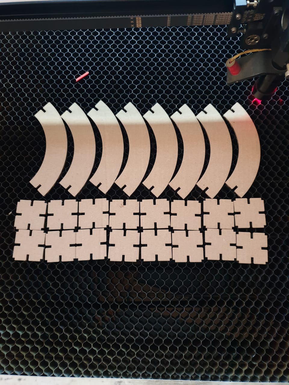
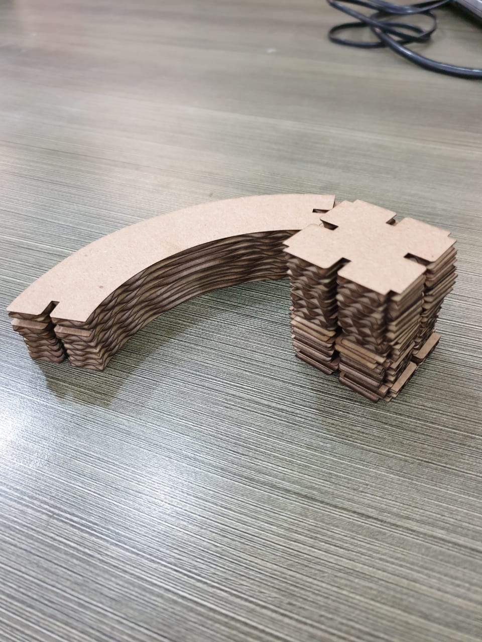
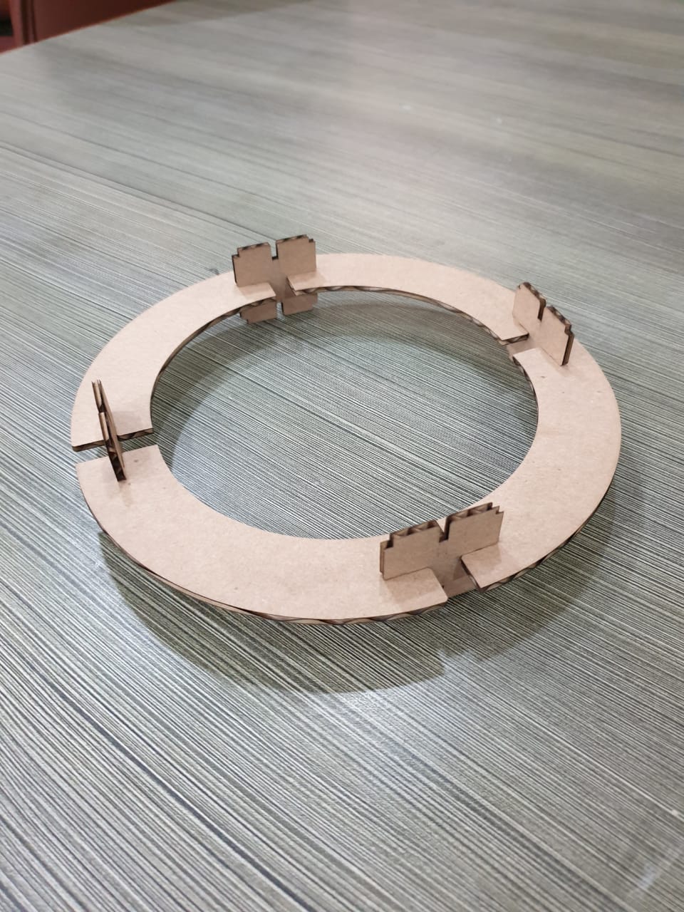
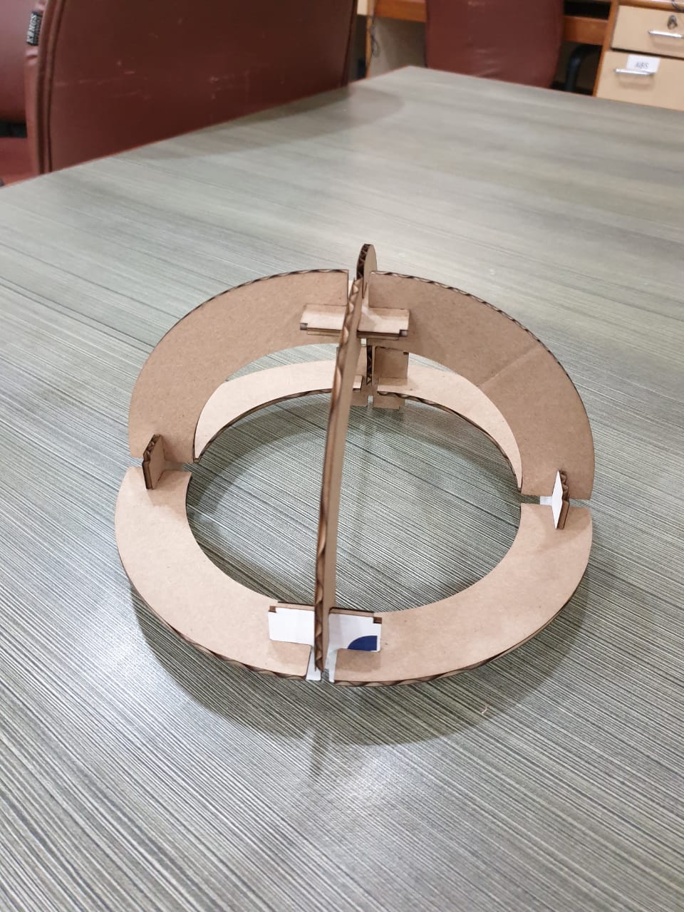
Assembly
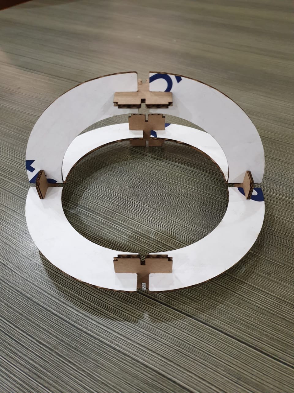
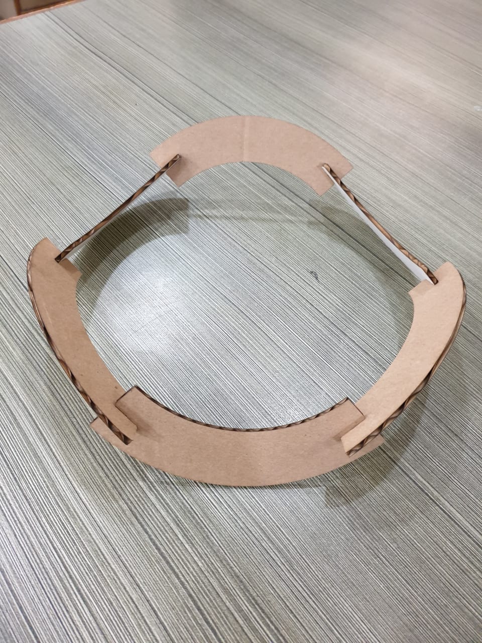
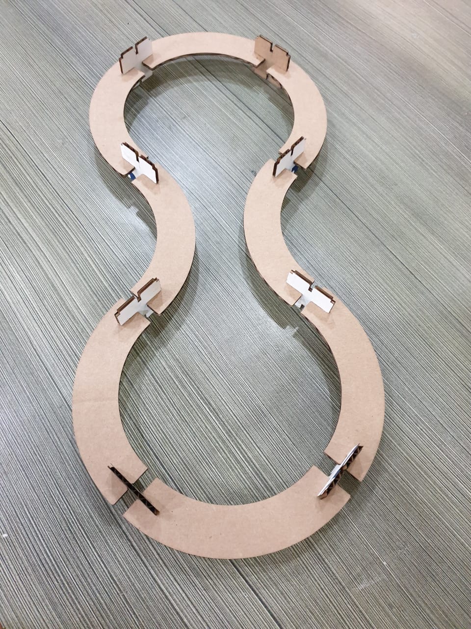
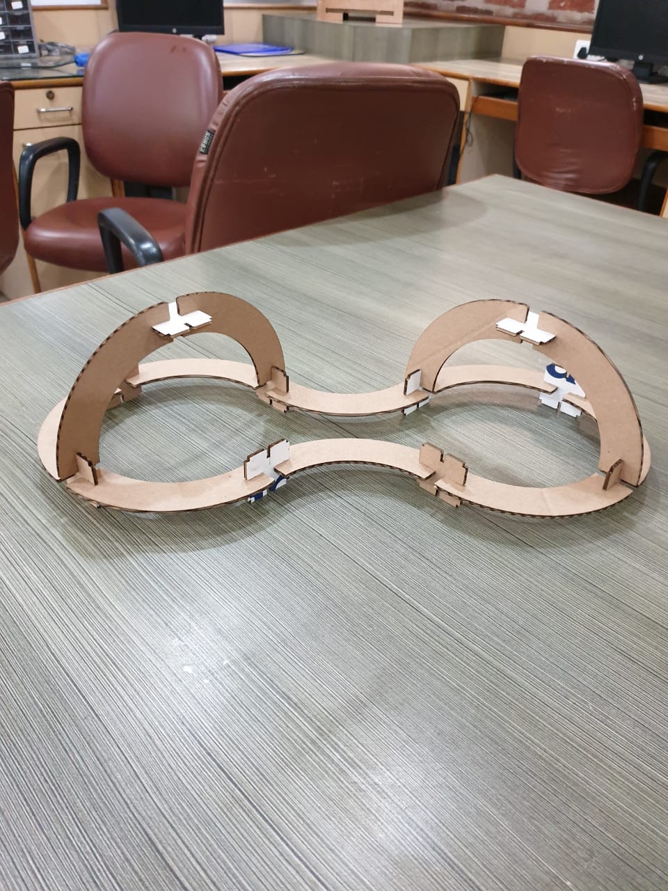
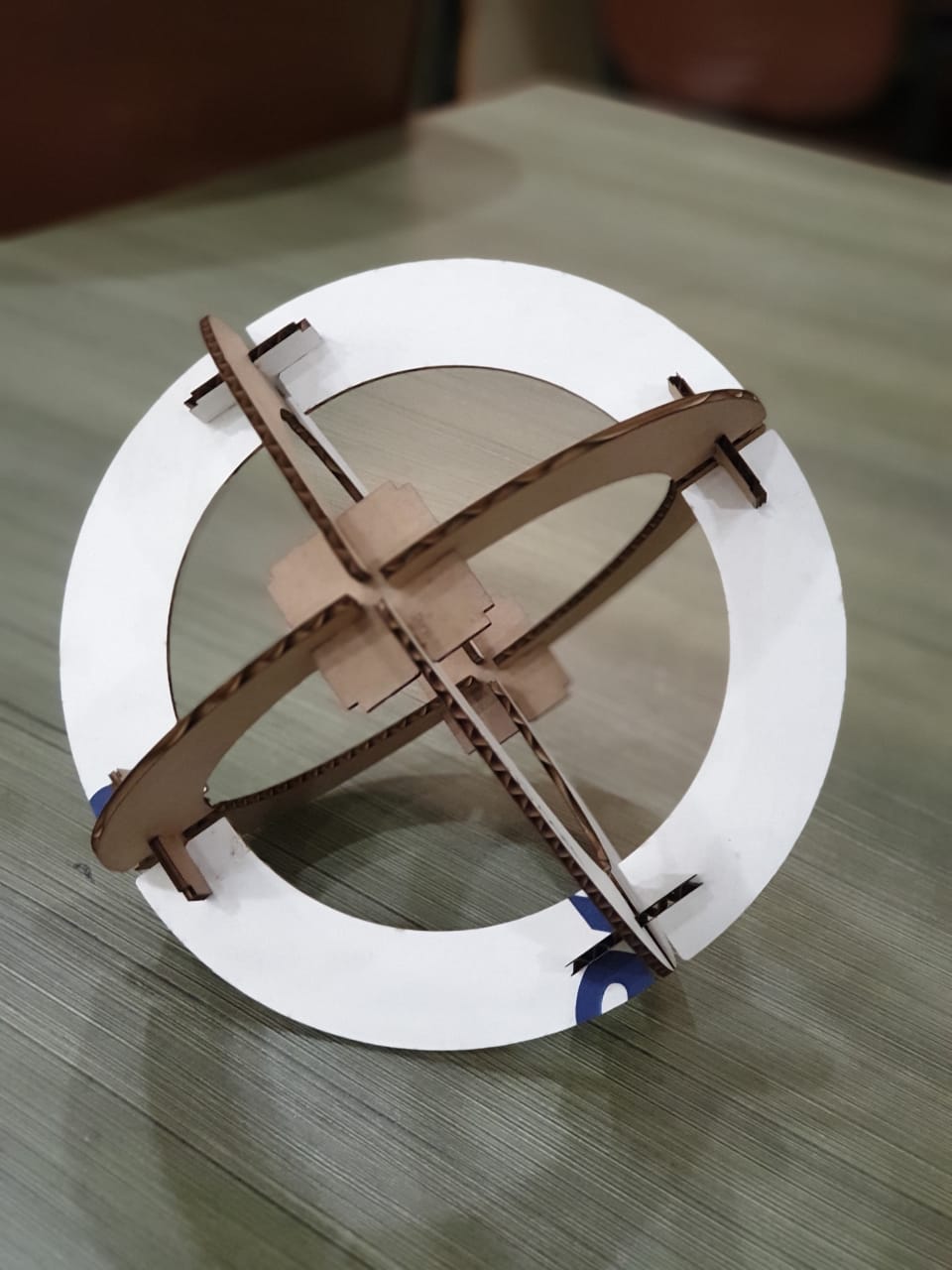
Vinyl cutting
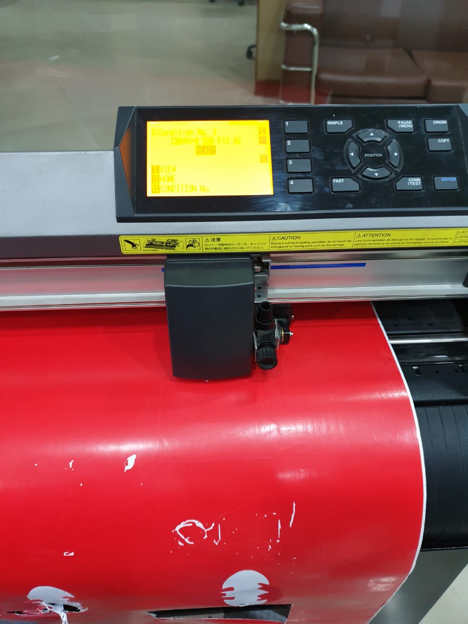
In our lab, we have Graphtec CE6000 vinyl cutter.
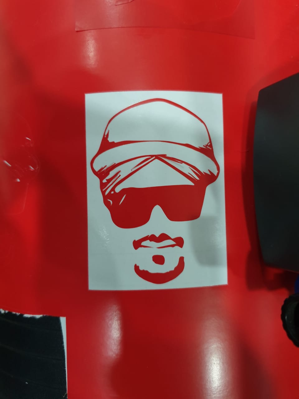
For vinyl cutting, I processed and cut my own image.
vectorizing own image
For this, I used CorelDRAW software.
steps
- Open the image and convert it into grayscale. Play with different settings like contrast, brightness, sharpness, etc to get the perfect effect.
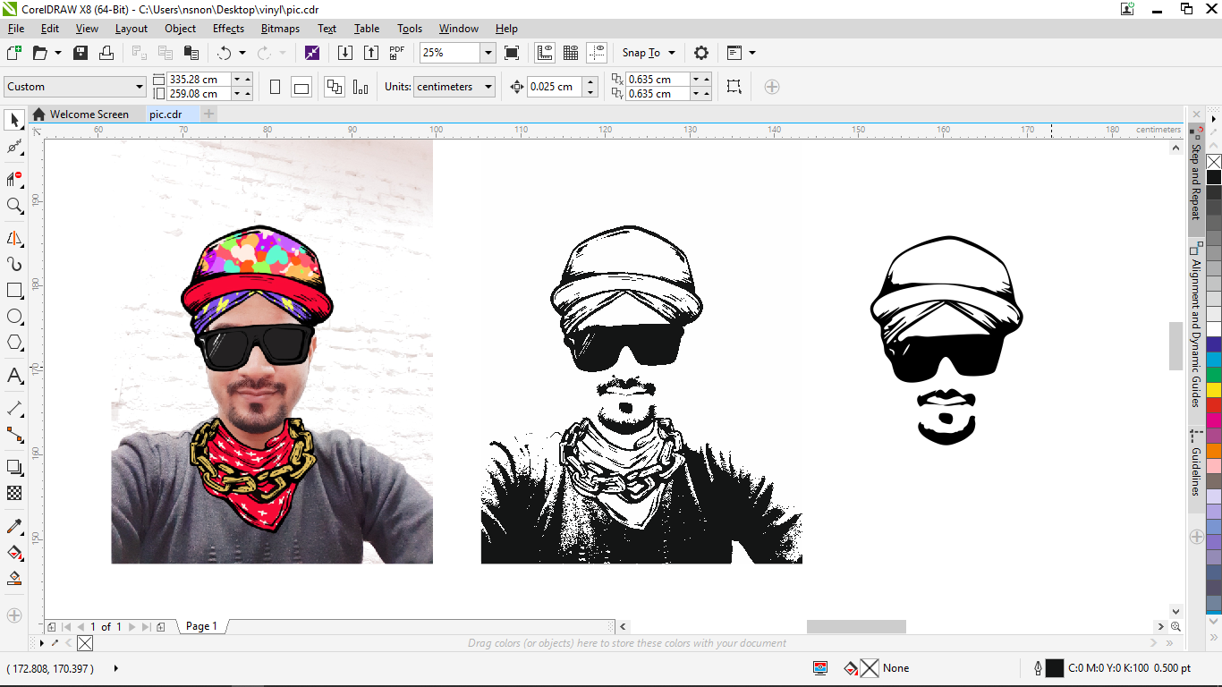
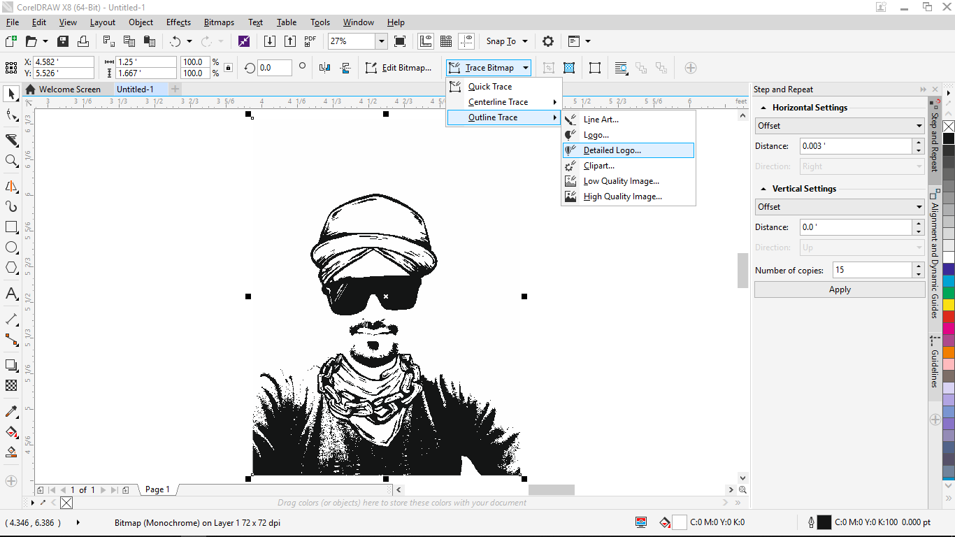
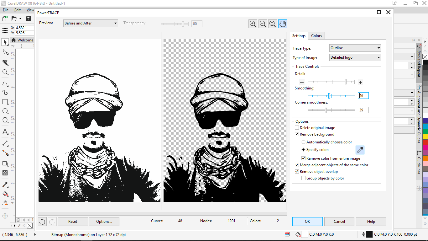
- Trace the bitmap image to convert it into the vector.( Trace Bitmap –> Outline trace –> Detailed logo). Here also, you can try different tracing options to get good results.

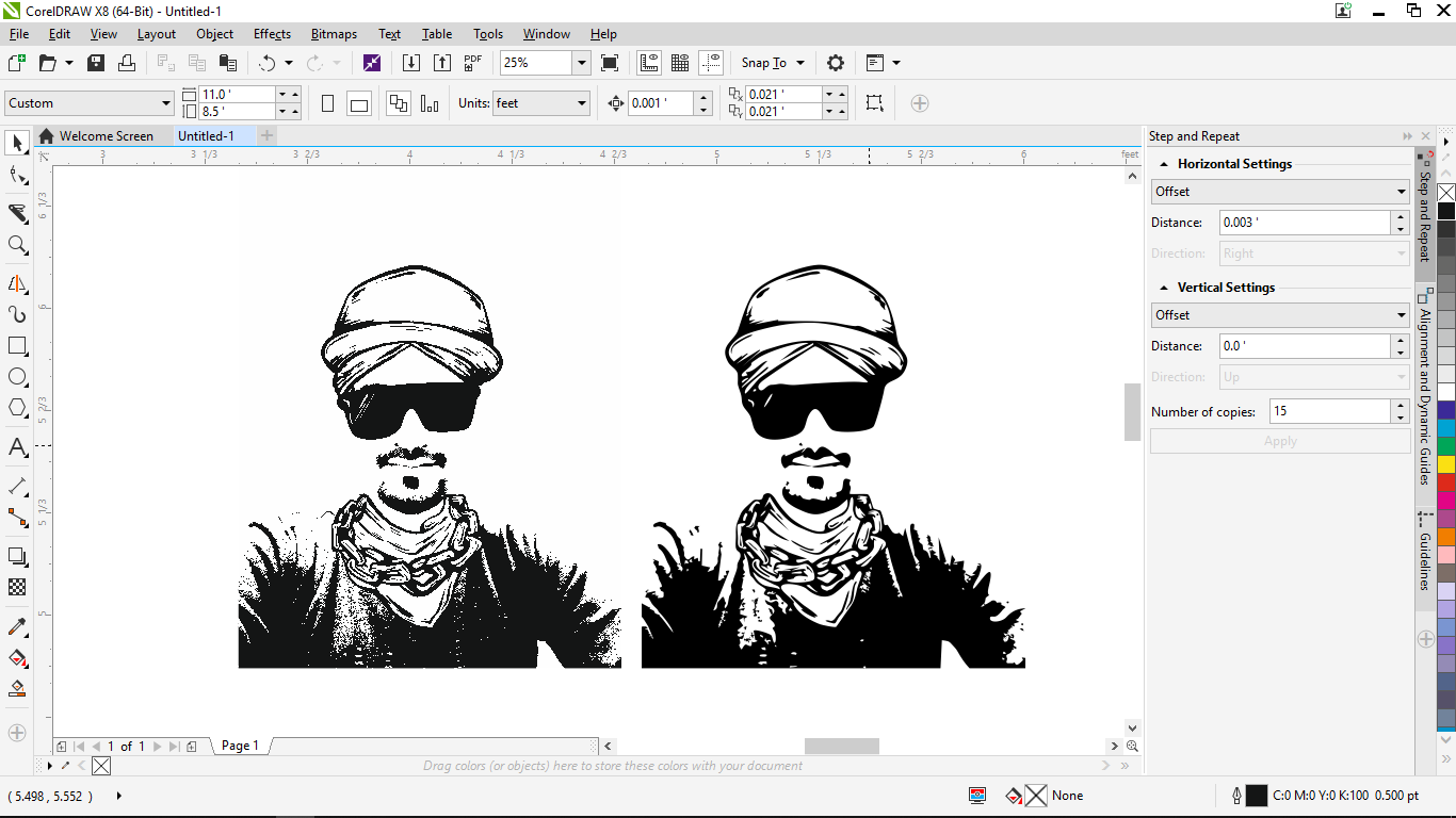
- I just wanted the face so I trimmed other parts.
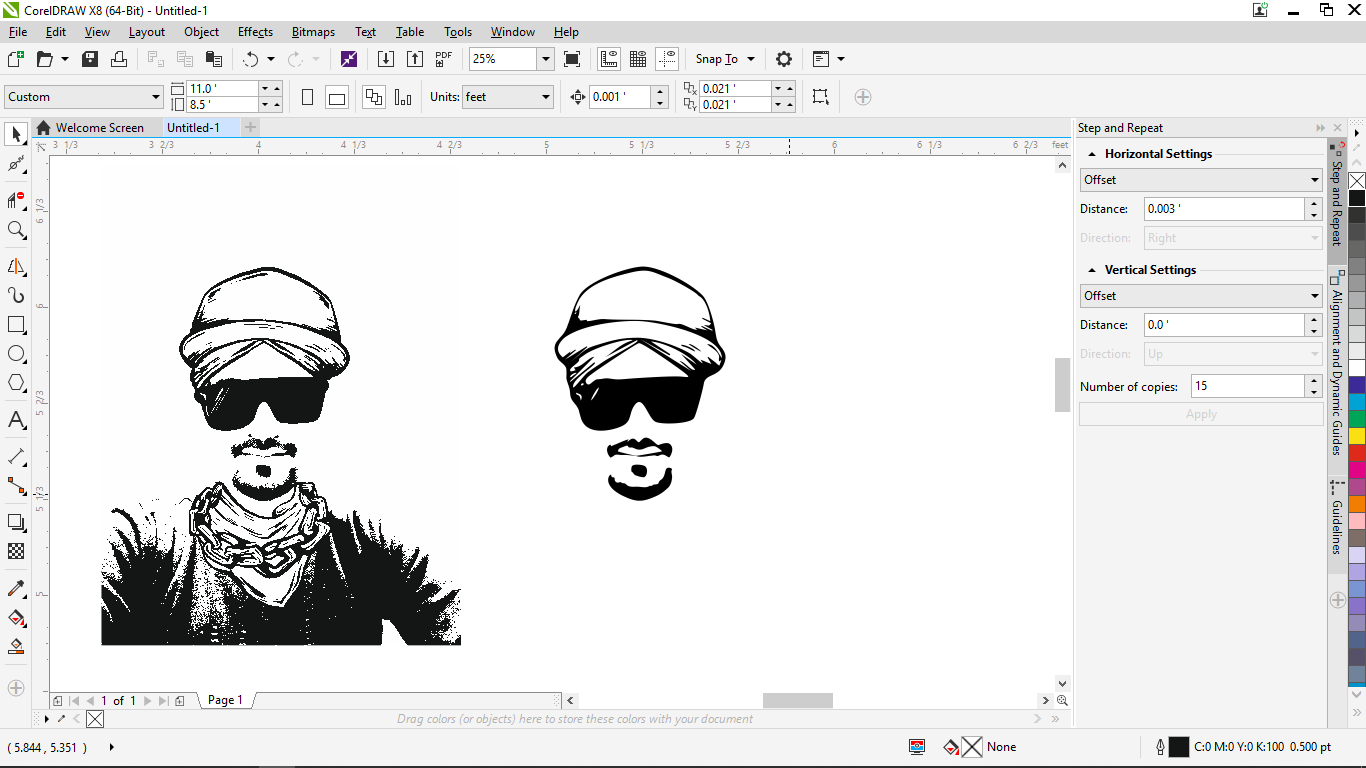
- Save it as a .dxf file.
Download the dxf file.
Graphtec studio
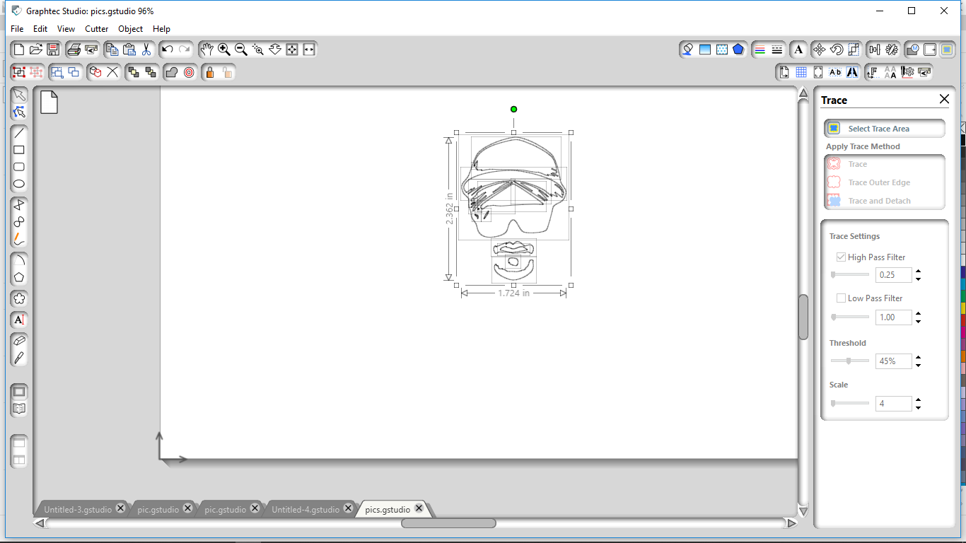
For operation Graphtec vinyl cutter, download the software Graphtec studio.
- Open the dxf file in the software.
- Select the trace area. then, trace the edges. Tracing setting which worked for me was- High pass filter- 0.25, uncheck low pass filter, threshold- 45% and scale- 4.
- Open the trace window. Here, set the cutting speed, acceleration, and cut force. I tried to cut at various speed but my design has very sharp corners so I finally reduced the speed to 1cm/sec and acceleration to 1. Cutting force is the force that blade applied on the vinyl while cutting. If it’s too much then with vinyl, the paper on the back would also cut.
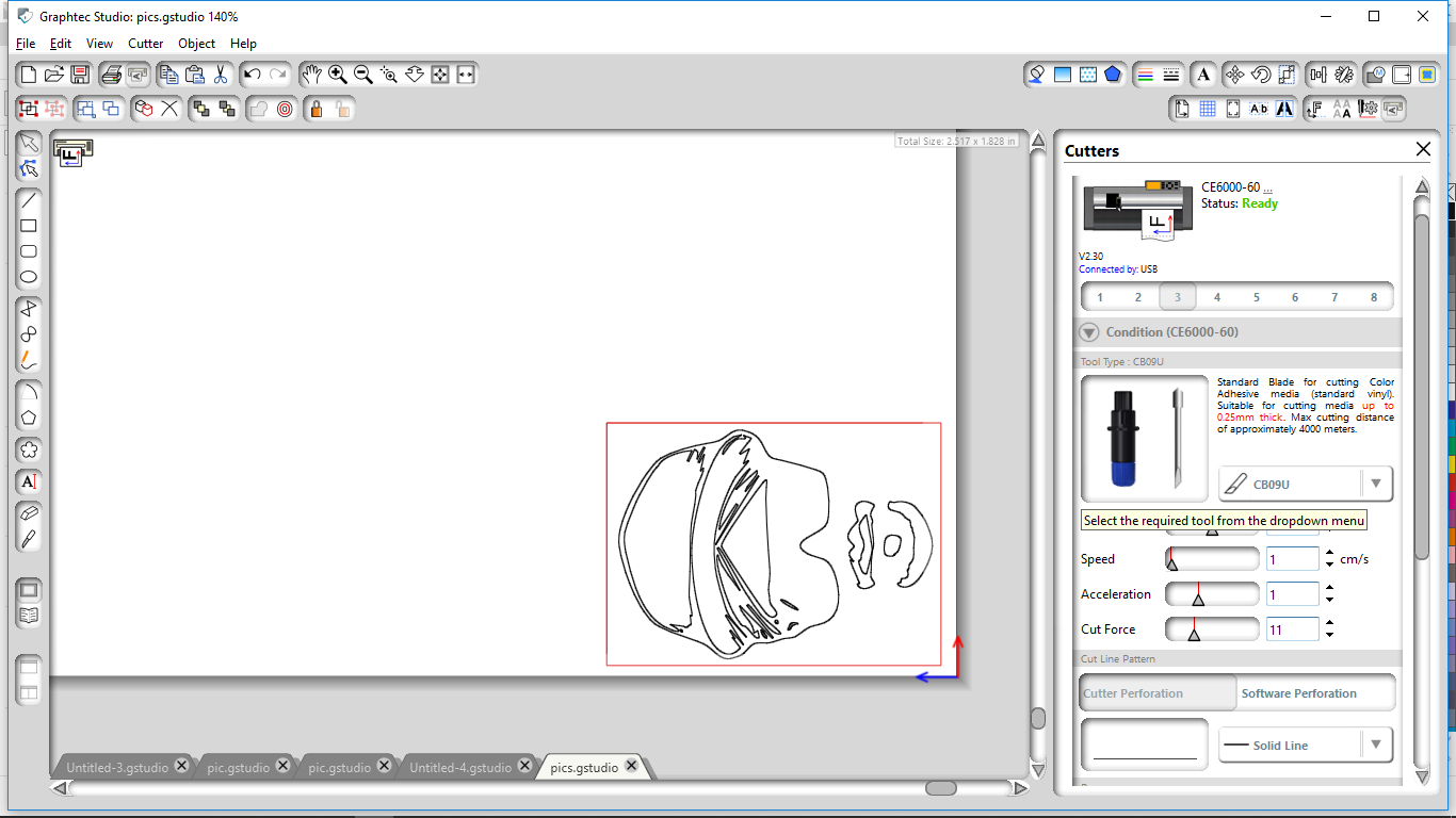
Processed file in Vinyl cutter
sending file to Graphtec for cutting
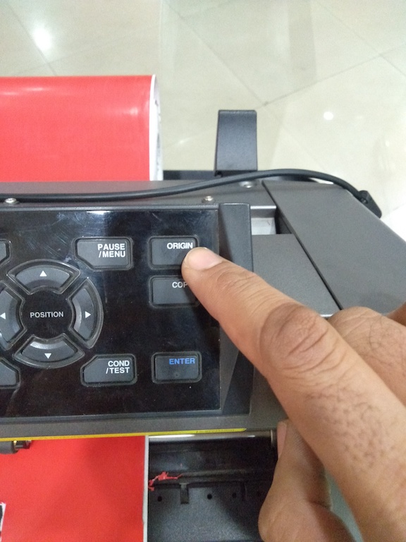
- Set the position of the blade from where you want to start cutting using four arrow keys on the machine.
- Set the origin.
- send the processed file for cutting by clicking “send to cutter” tab in the Graphtec studio window.
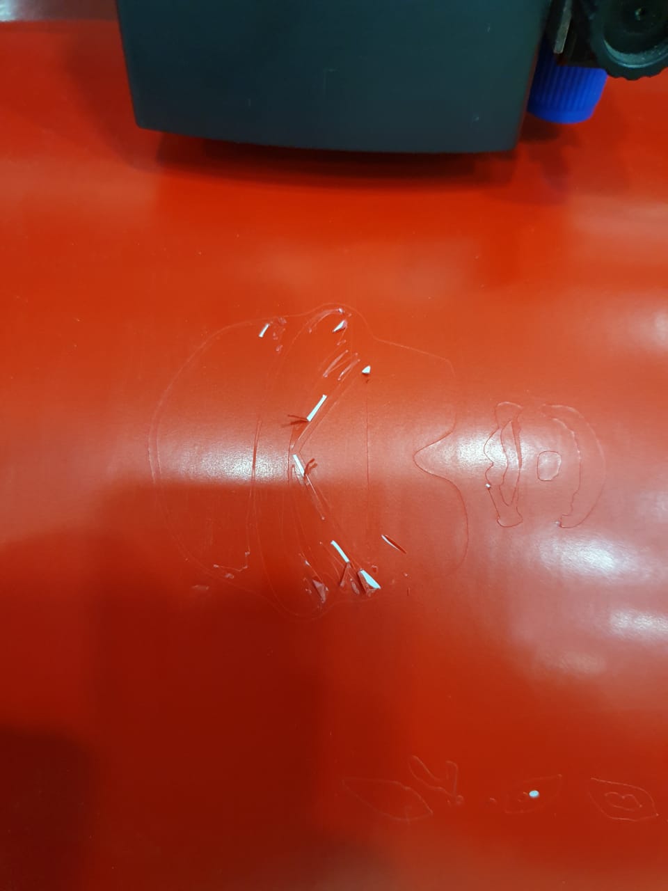
- Once, the cutting completes, remove the waste vinyl using a knife or any sharp object.
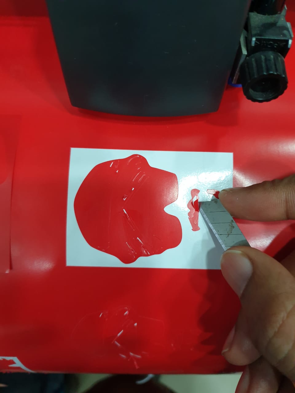
-
My perfect vinyl cut :)
-
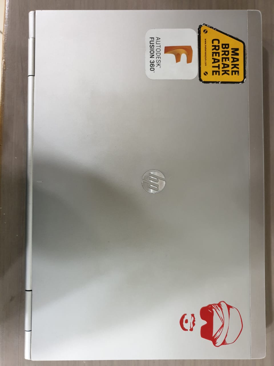
I pasted it on my laptop. Use transfer tape for this purpose.
Learning outcomes
- I learned how to use a laser cutter. Importance of speed and power combination for different modes. I got to know about the kerf so that which is to keep in mind while designing.
- I used Graphtec first time. It was a little tricky to cut the sharp corners. But ultimately I able to did it by playing with speed and acceleration settings.
- Learned about the importance of parametric designs.
- I enjoyed assembling press fit kit. It was amazing and the same as we used to play with legos in childhood.

This work is licensed under a Creative Commons Attribution-NonCommercial-ShareAlike 4.0 International License.