Machine
In this week I am going to design my machine; I work alone so I have had to work hard and with much organitation. The machine I've designed is a compressor tester: the structure of it and the information about it are visibile in this site where I've taken inspiration. The main mechanic structure of this system is the rack and pinion: about this I' ve search in this site[https://github.com/fellesverkstedet/fabricatable-machines/tree/master/chamferrail ] how it work so I've started to design (and print) the rack and pinion and from these I've build the whole structure. Before of all I have tried to build the rack and pinion separately and then I have tried to simulate the working of the system:
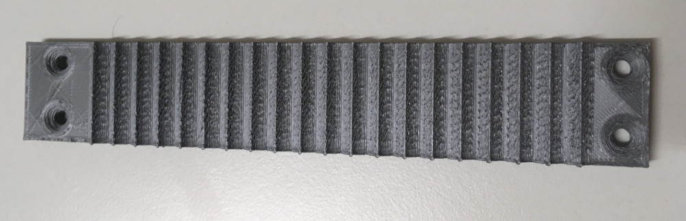
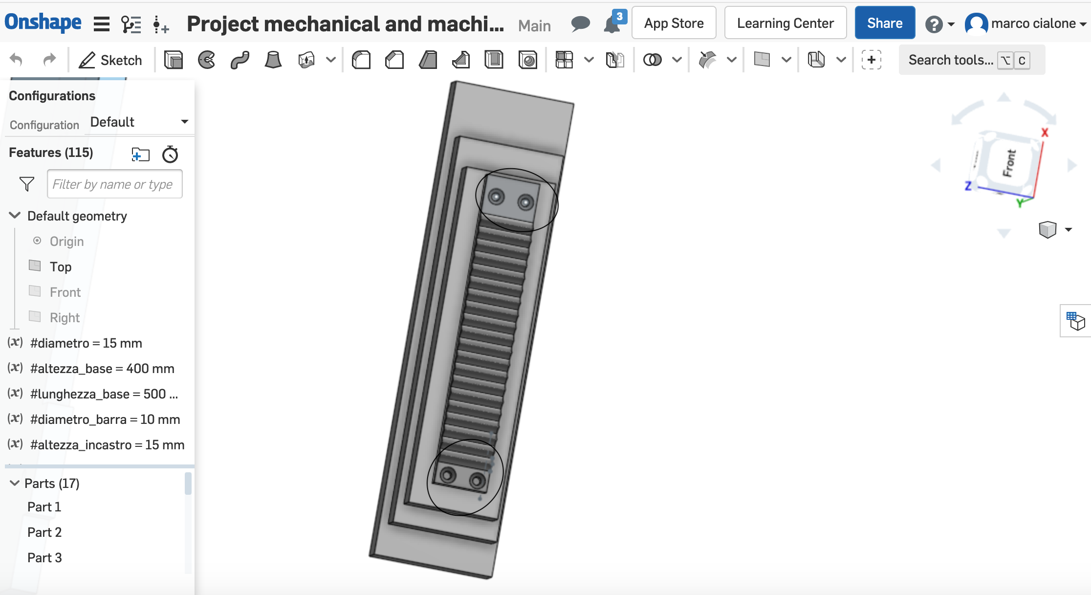 in the base of the rack I've done 4 holes for the screws because I am going to put it on 3 block of wood to have it lifted up because the pinion has to slide on a bar
the pinion structure is the complementary of the rack :
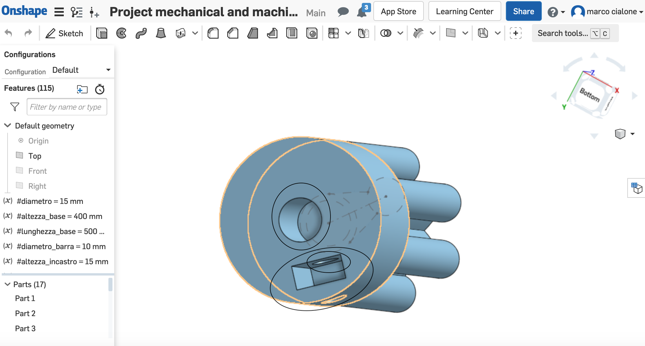
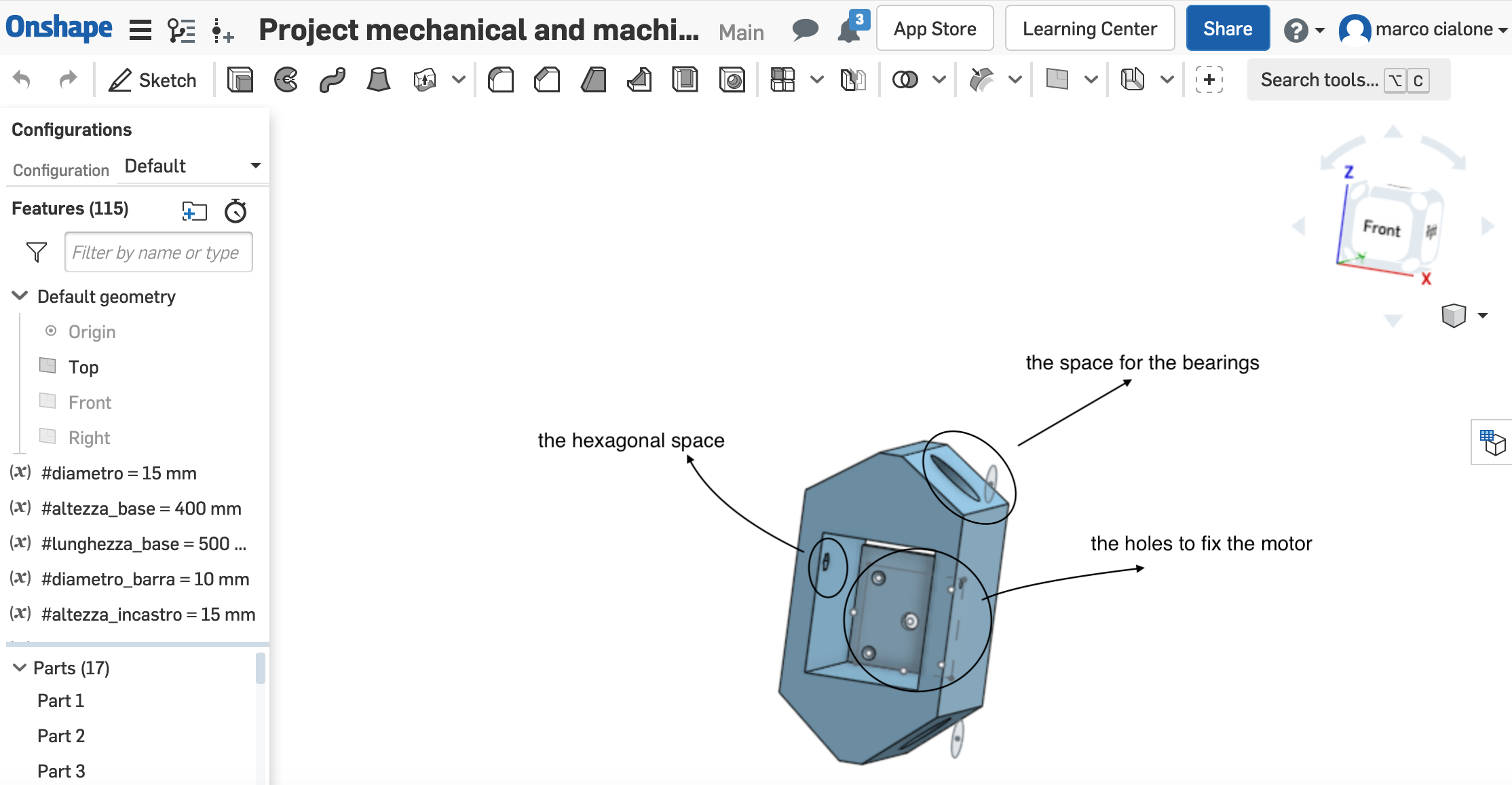
we also can see the circular and rectangular holes: in the circular one I have to put the spindle of the motor and from the rectangular one I am going to put the hexagonal junction of the screws in order to stop the pinion around the spindle.
In my system the rack is fixed and my pinion linked to the motor flows through the "sled". In this sled I have done a place where I've put the motor and I have fixed it with 2 screws . I've also than a space for the screws of the compressor block. And finally I have done up and done two slot for the linear bearings (so the bar )
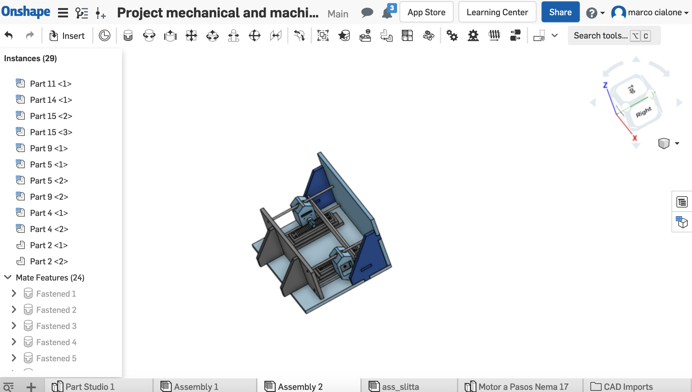
In the assembly of the project I've simulated the machine joining every component : in this way I have the certainty that the system component are perfectly joinable.
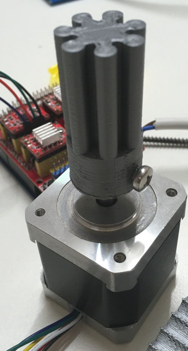
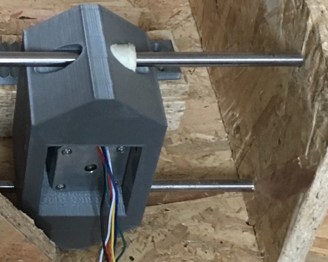
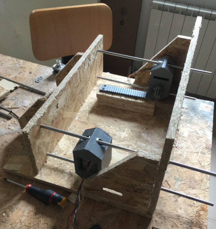
So at the end when I have finished the design I have printed every componenet and I have assemblied it.
In the hardware point of view I've had to do the wiring of the motor: I've linked the wire in our correct position with this scheme:
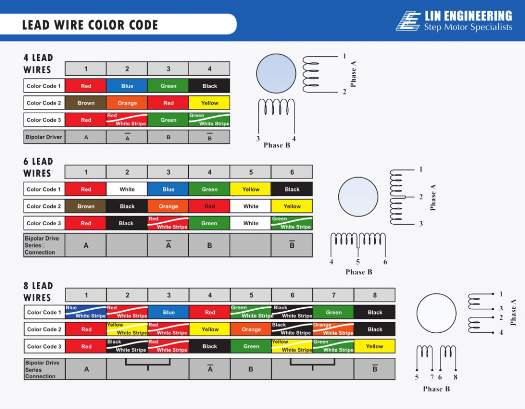
and seeing this tutorial and others: I linked the arduino's 5v to my computer and I power the cnc shels with a 12v power supply.
The software used in this scope is grbl; to launch it I have had to do some step:
- I' ve dowloaded the Grlb source code on github(https://github.com/grbl/grbl) (download zip)
- then we need to launch arduino IDE
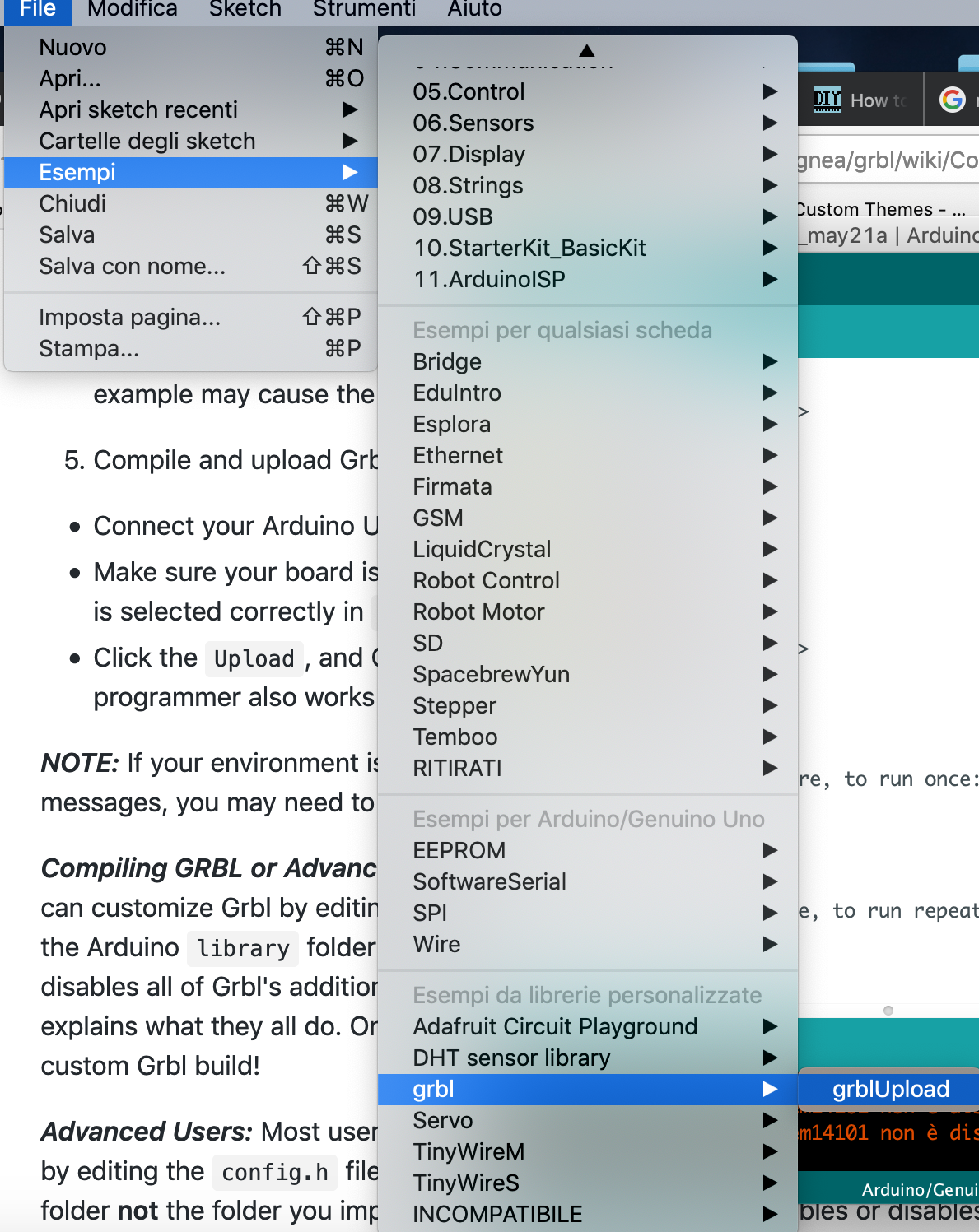
- include librery(grbl) adding the zip file
- so It is now visible in the library list (in provided by third parties)
- now we launch the example code of the library Grbl and launch the gcode in the plot serial
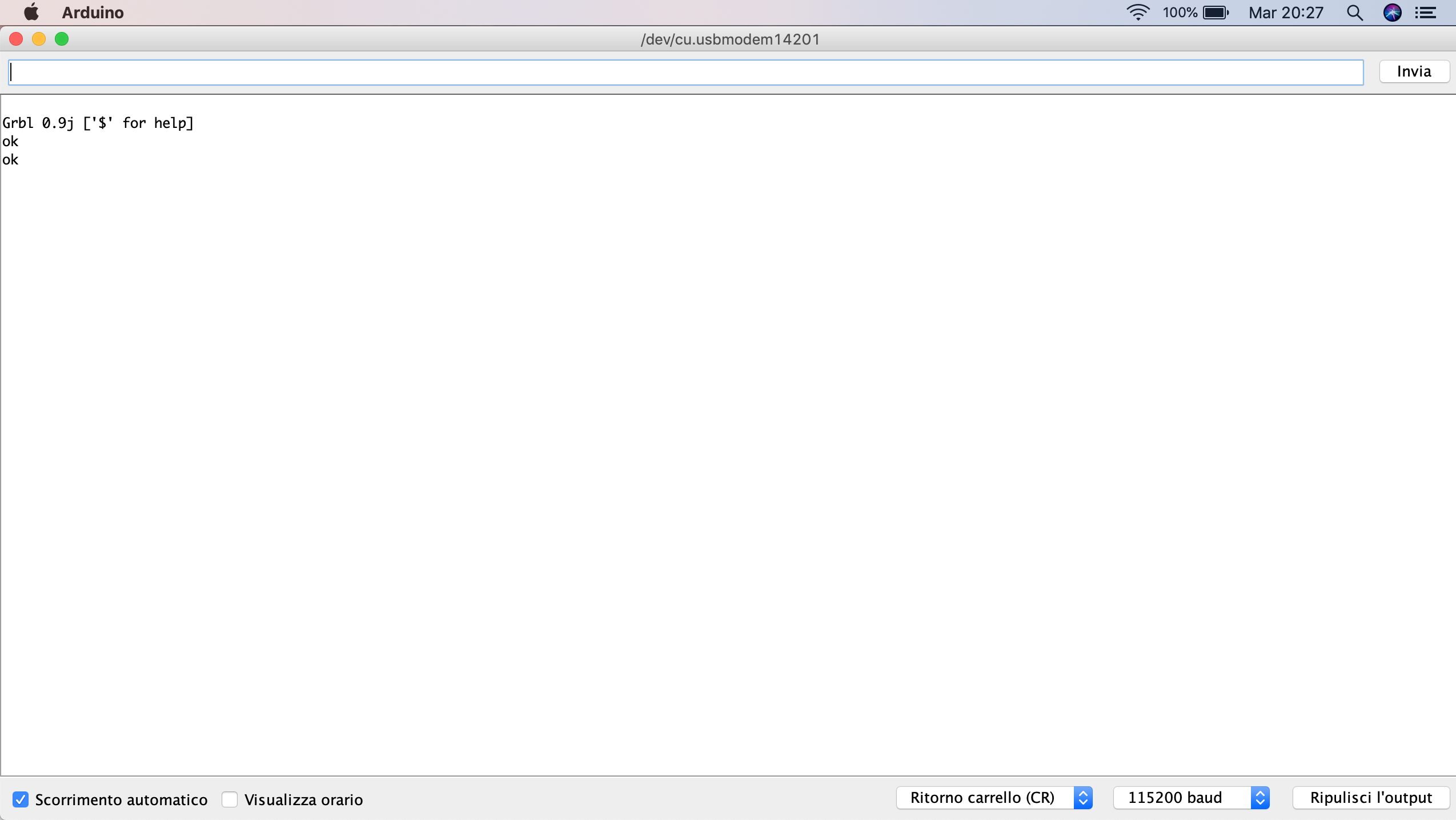
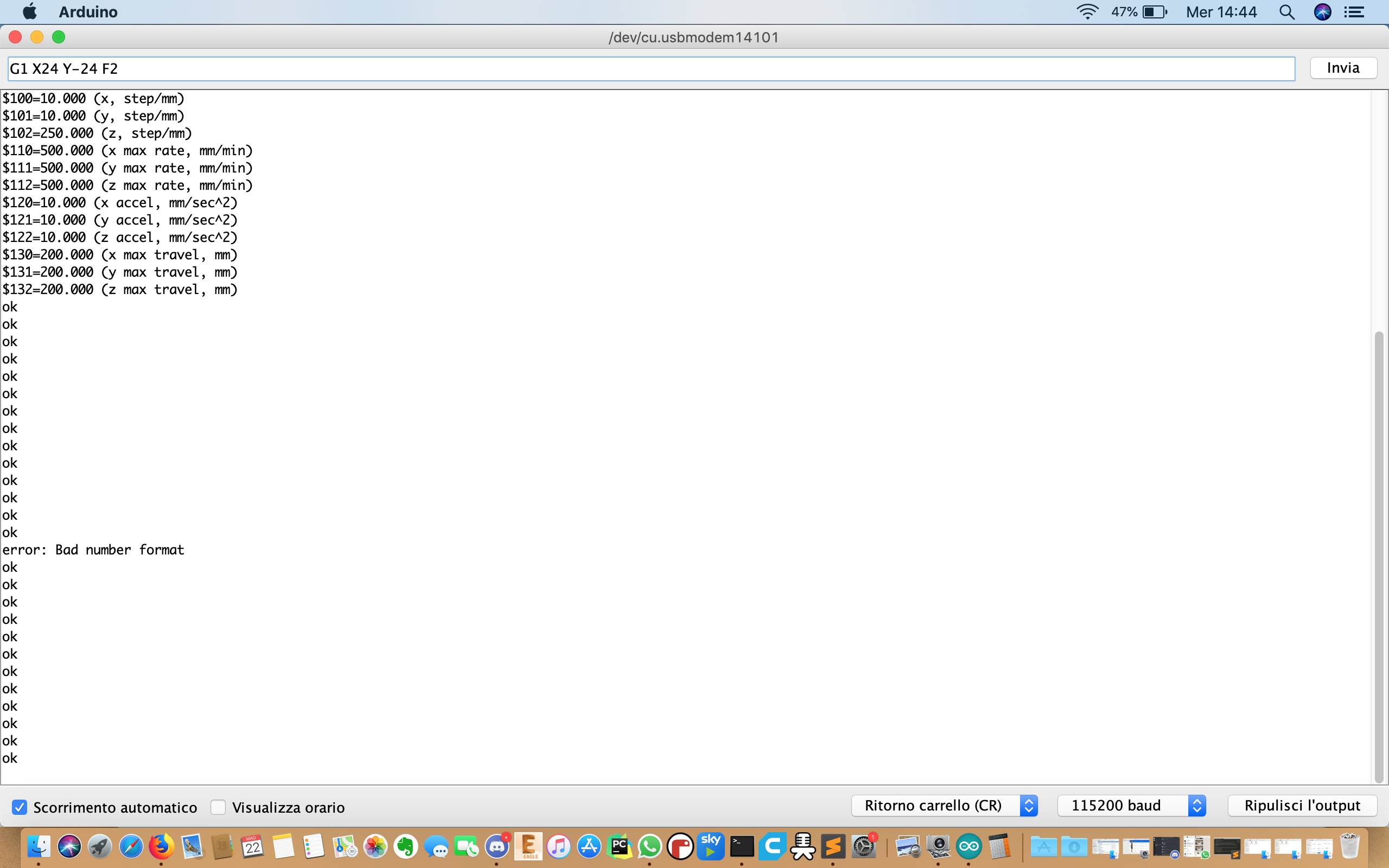
When I've load the sketch I am going to see this screen in the serial port.
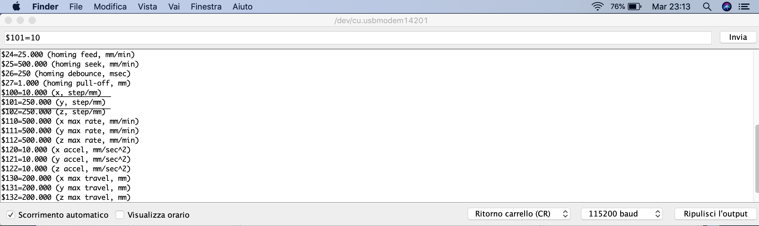
I see some tutorials to give information about the code instruction:
- an important instruction is the changing of the setting of the step/mm: in my case I use a small value of this because I don't need more "resolution" in the movement of my pinon: I select:
$$100=10 ( (x,step/mm) )
I have done this for the other motor too (y axis) ,
$$101=10
- I also set with the command:
G91
the relative position value of the movement: in this way I select each time how much is my movement lenght.
I've used two motor to have more power because the rack and pinion system needed to grip: this motor are put in specular position so the positive direction for one is the negative one for the other(they aren't moving different axis). In this tutorial I see the command to move them togheter :
G1 X-24 Y24 F10
- The
F10command is about the feed rate: I don't need a great feedrate because in this way the rack and pinion system don't work weel (the motor could be lose this phases)
- the rack and pinion system work well:
video from Marco Cialone on Vimeo.
To see my machine working go to this link