Input devices
Assignement individual
measure something: add a sensor to a microcontroller board that you have designed and read it
Group assignement
probe an input device's analog levels and digital signals
Assignement work
For this week, I take the oppurtunity to do an other board bigger than the hello_board one where I can expose some pin for different sensor. It could be useful for the work of my final project too and to improve my ability with soldering and with Eagle programm. So I have redone all the step ,doing in the week of electronic production and design ,to create a board. In fact I have done:
- the design of the schematic in eagle
- the design of the board
- I export the png of my board
- I edit this png to create the toolpath read by the roland milling machine
The modification of my png with GIMP
when I have exported my png from eagle I have a file which show me the track and component of my board but is not suitable for the creation of my toolpath because for it, i need three separeted file of my trace, outline and my case also the holes file.
so I edit my png in that way:
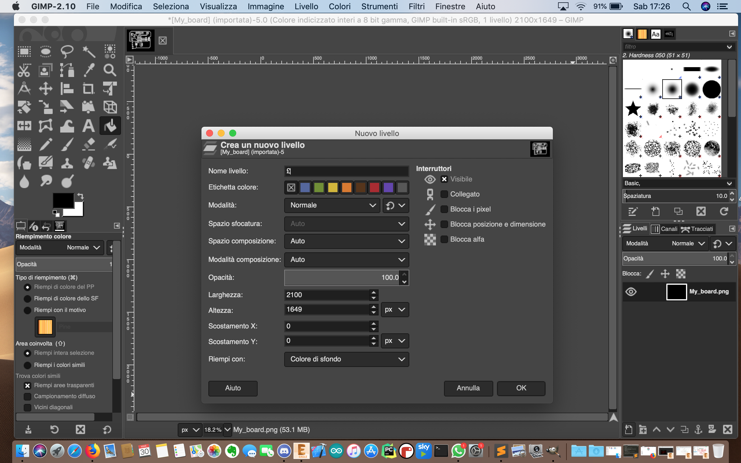
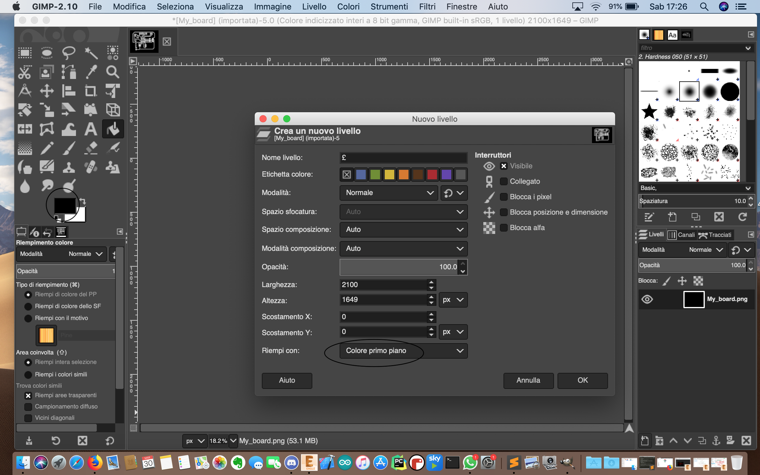
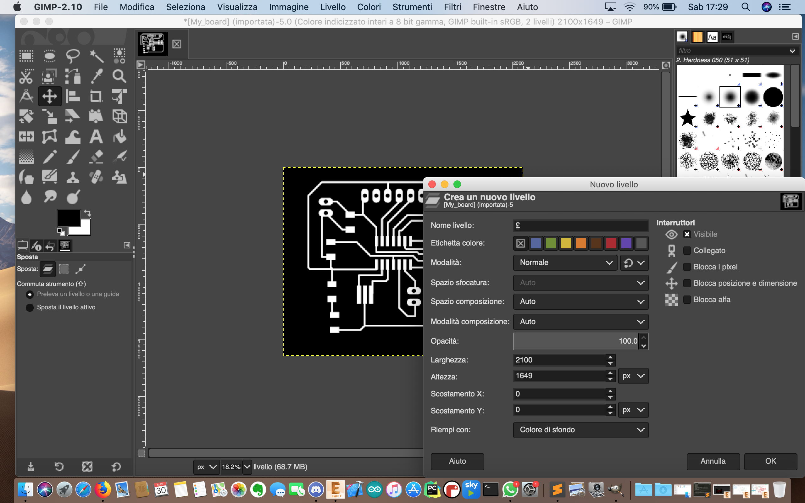
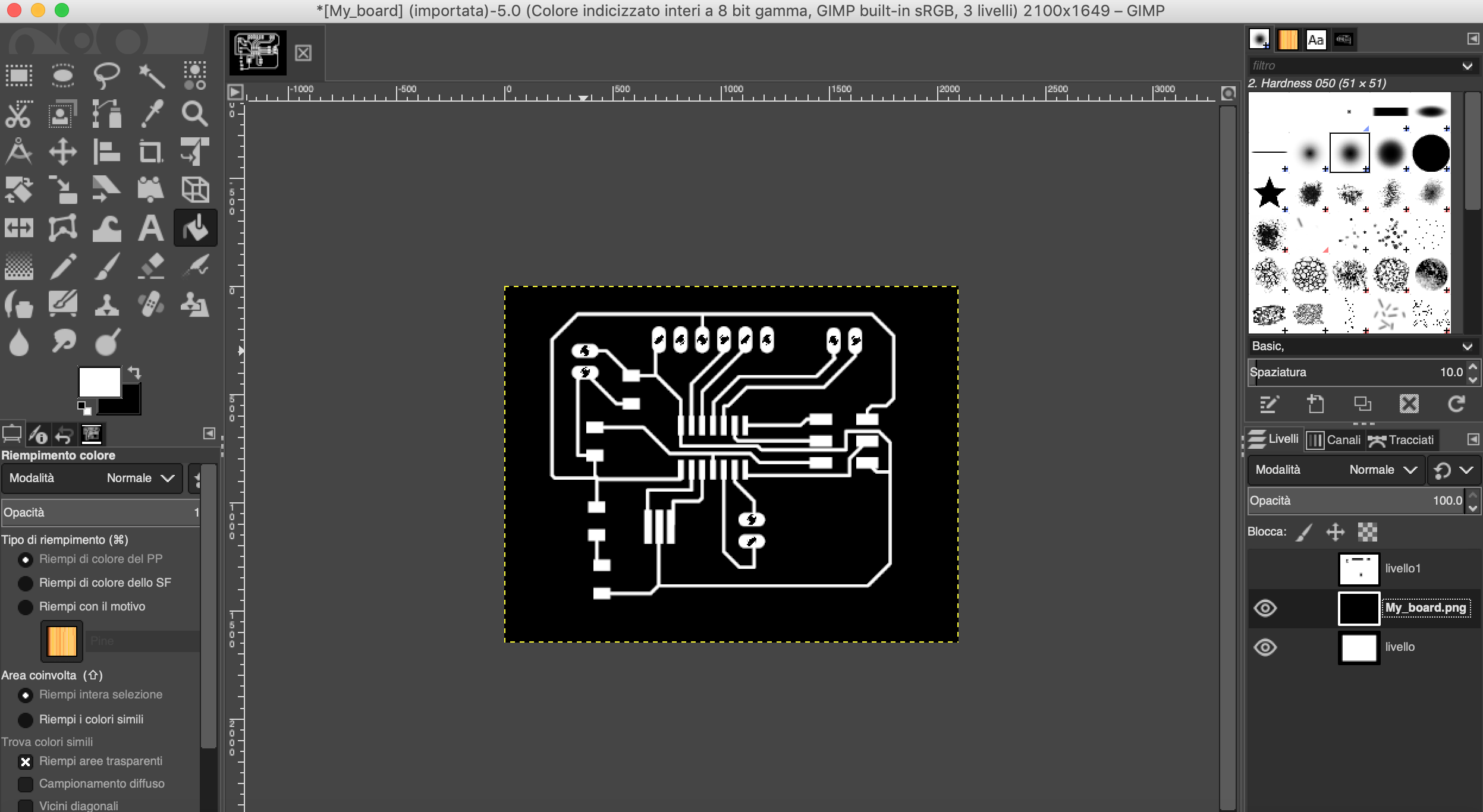
I export my png file in gimp and I create an other level on gimp:
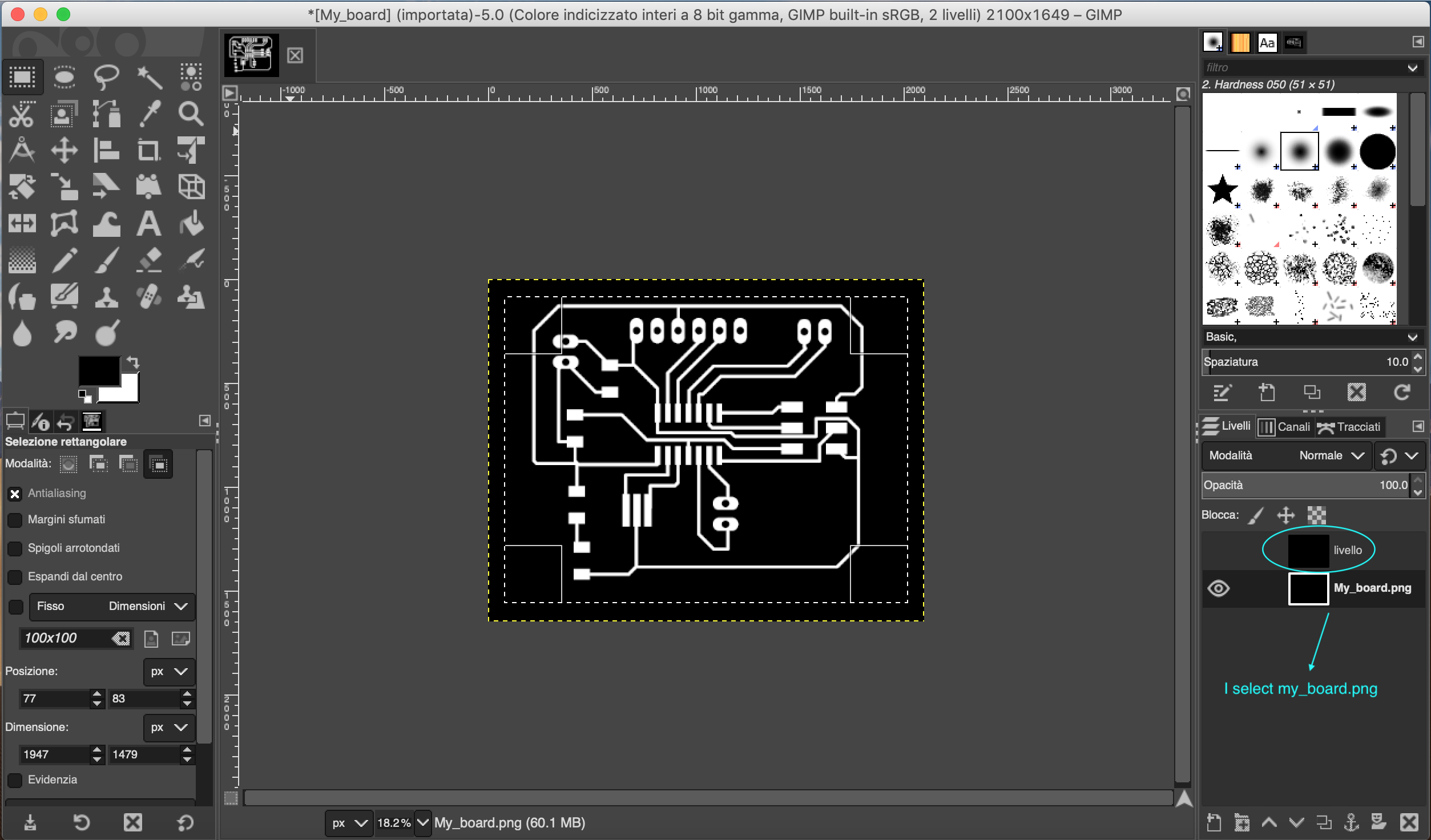
I set this new level at the top of the hierarchy and I select the my board.png
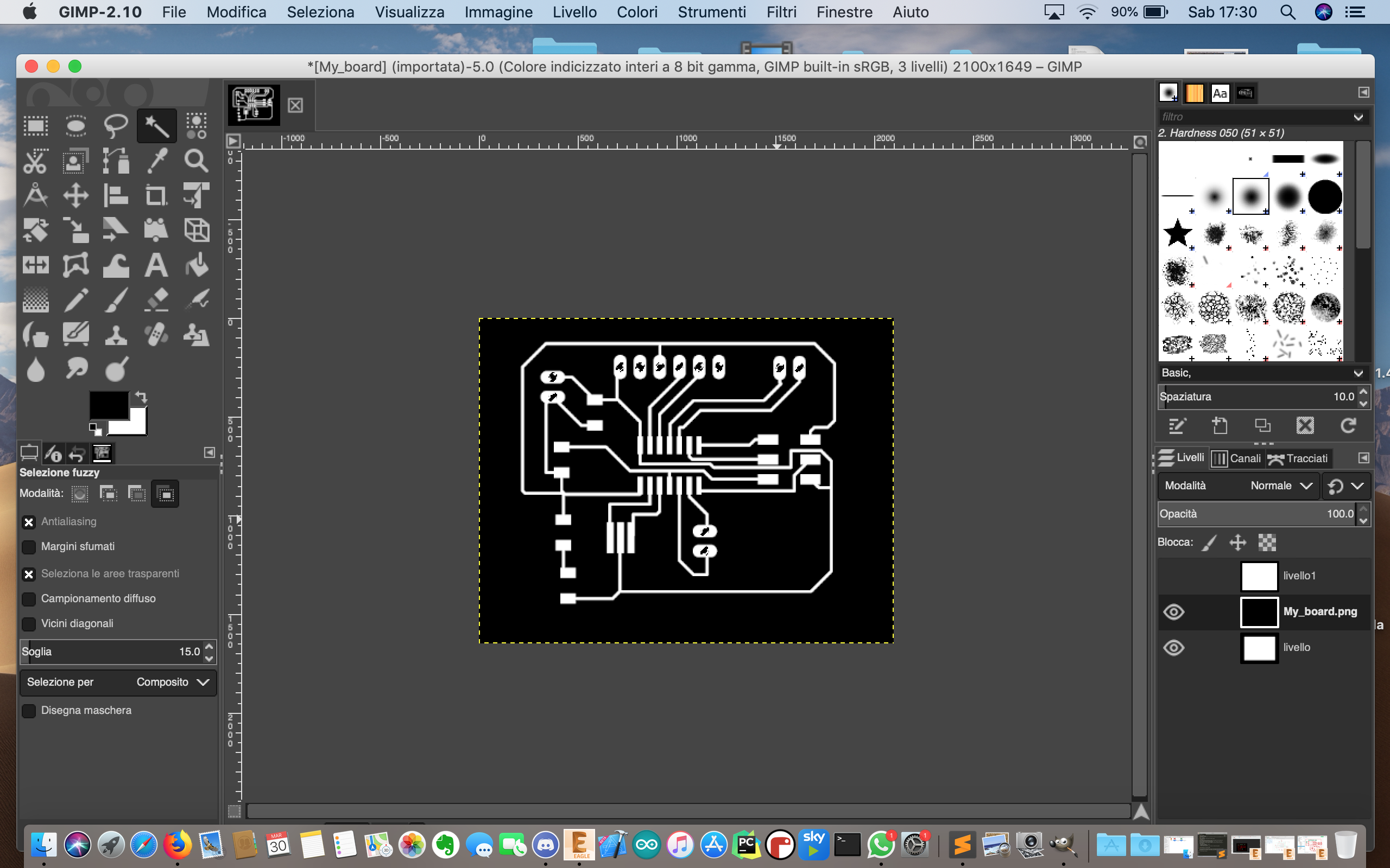
so I do a selection in the my board.png
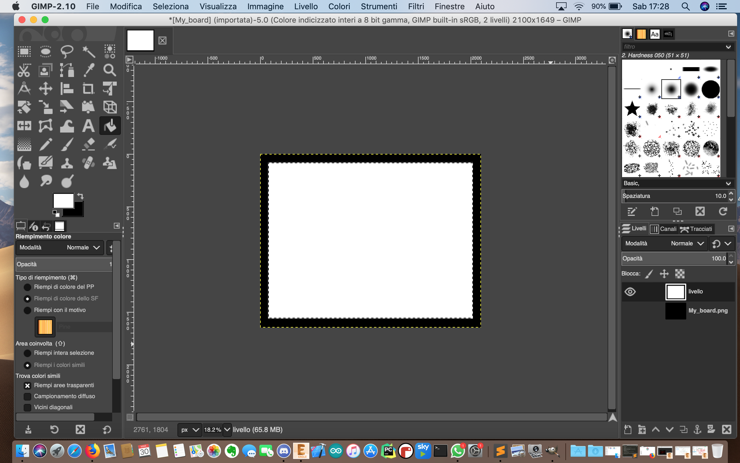
and then I have gone in my level at the top of the hierarchy and I have filled my selection with the white colour
then I have created the last level when I am going to draw the holes:
in order to do this I do the selection of the holes in my board png and I use this selection to fill it in the last level:
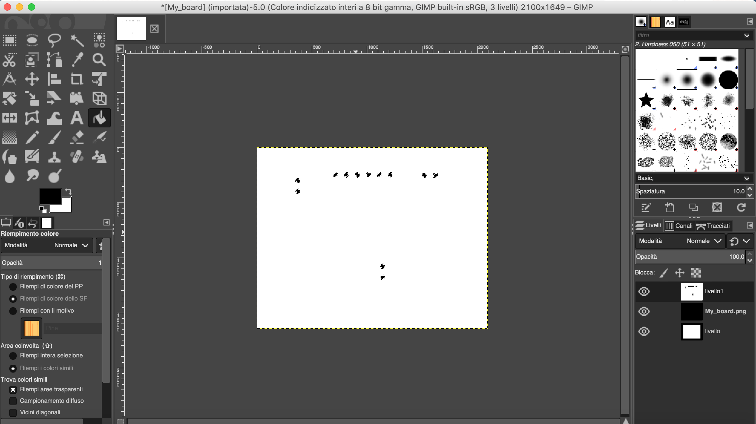
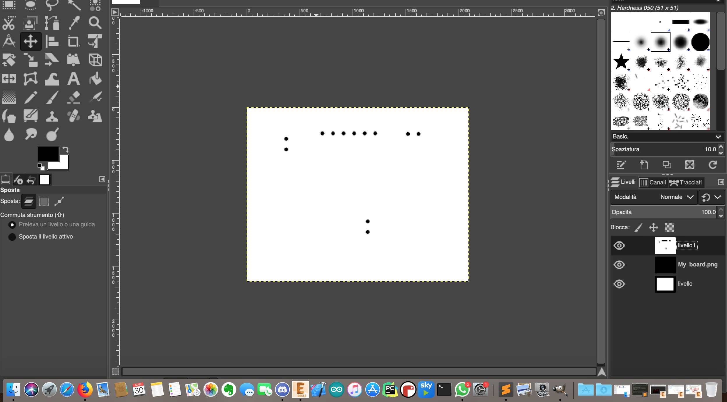
I also fill the holes with the colour white
at the end I export this 3 file .png that I am going to useit in order to do of my toolpaths
and now I can do my toolpath as I have done in the week of electroniic design
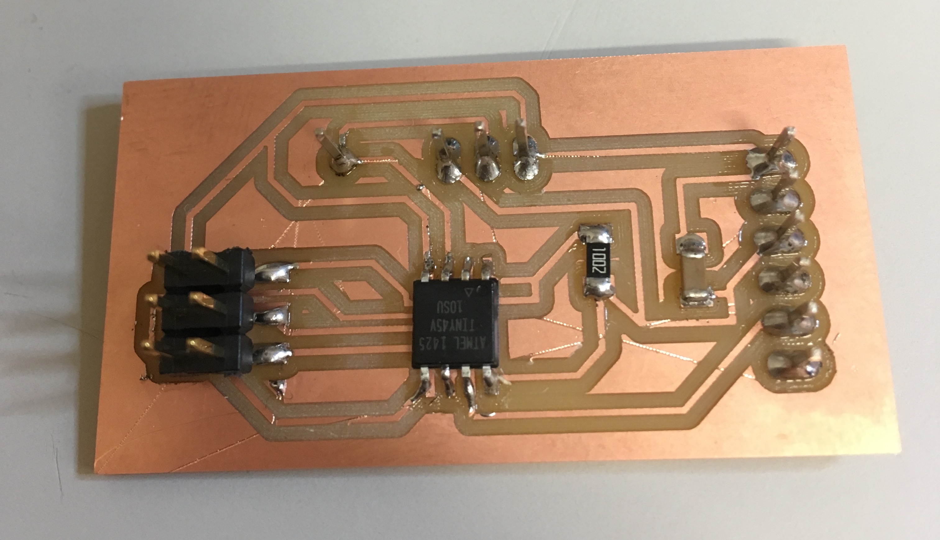
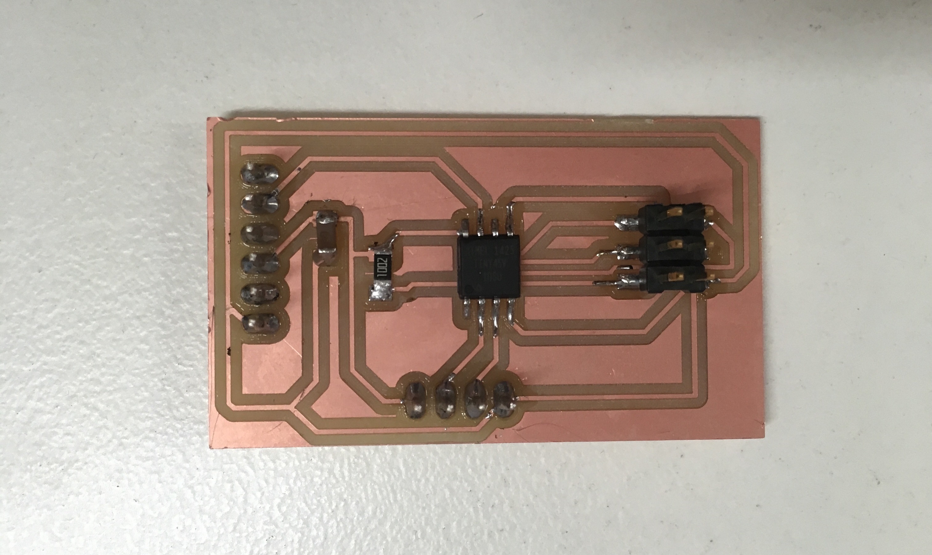
The boars of Pyroelectric sensor
I want to create this sensor in order to use it for my final project:
this sensor could be usefull to know if the olives in my machine are put on the grid.
in fact it is a sensor which controll a movement of a thing.
I've designed the board in this way because it has a simple unraveling; I've decided to expose the pin of the out of the sensor.
error of my board creation
I have two main error doing my board: - eagle file - soldering error
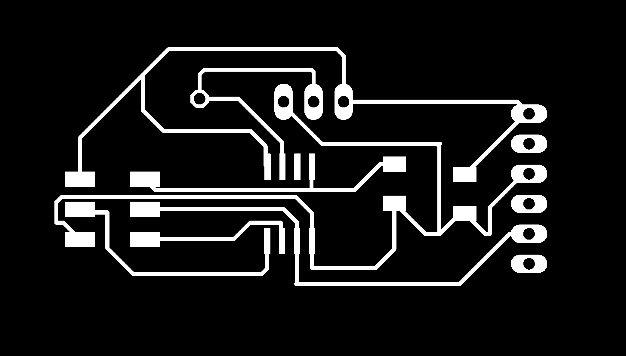
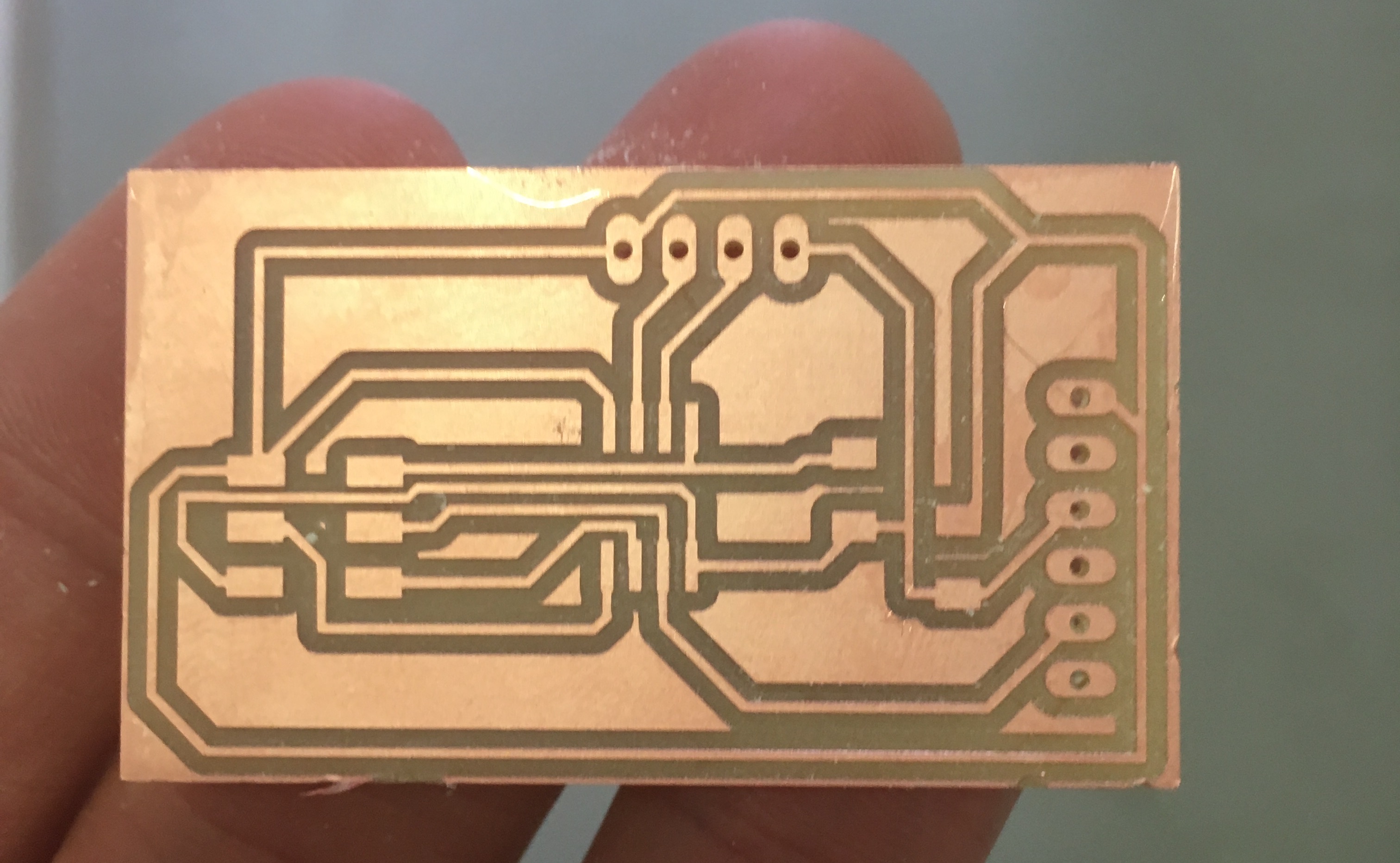
my error is about the setting of the DRC clearence that I have maintain with the default setting and not with 17mil:
so the eagle check didn't advise about the error but when I have milled with my milling machine the trace of my board are milled badly. this is the png exported from eagle:
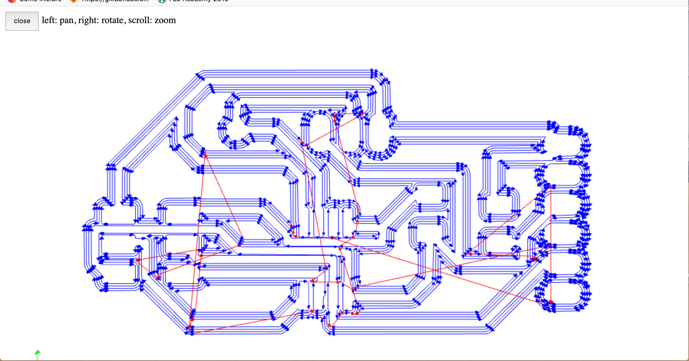
In the second board that I have milled I set the correct setting in DRC and I have this toolpath correct
but unfortunately I have used a dual layer board so when I have soldered the header of the fdti I have link the vcc in each exposed pin of it.
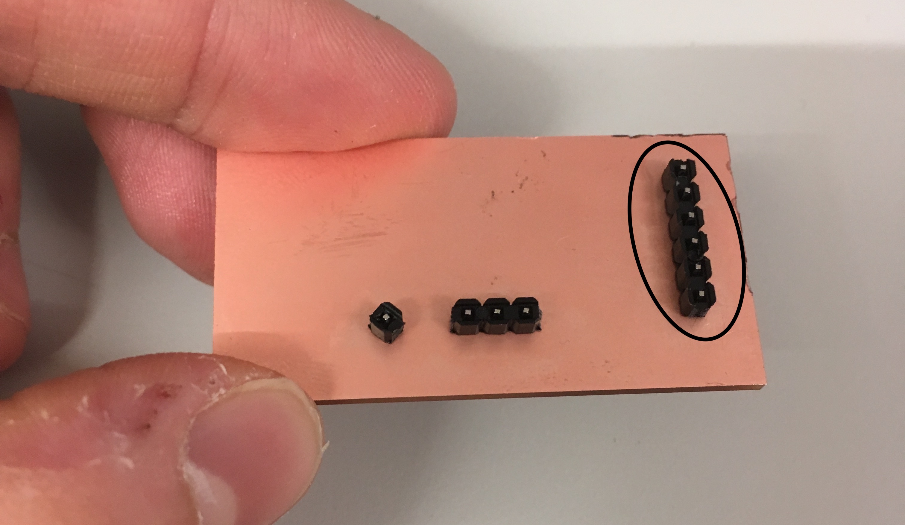
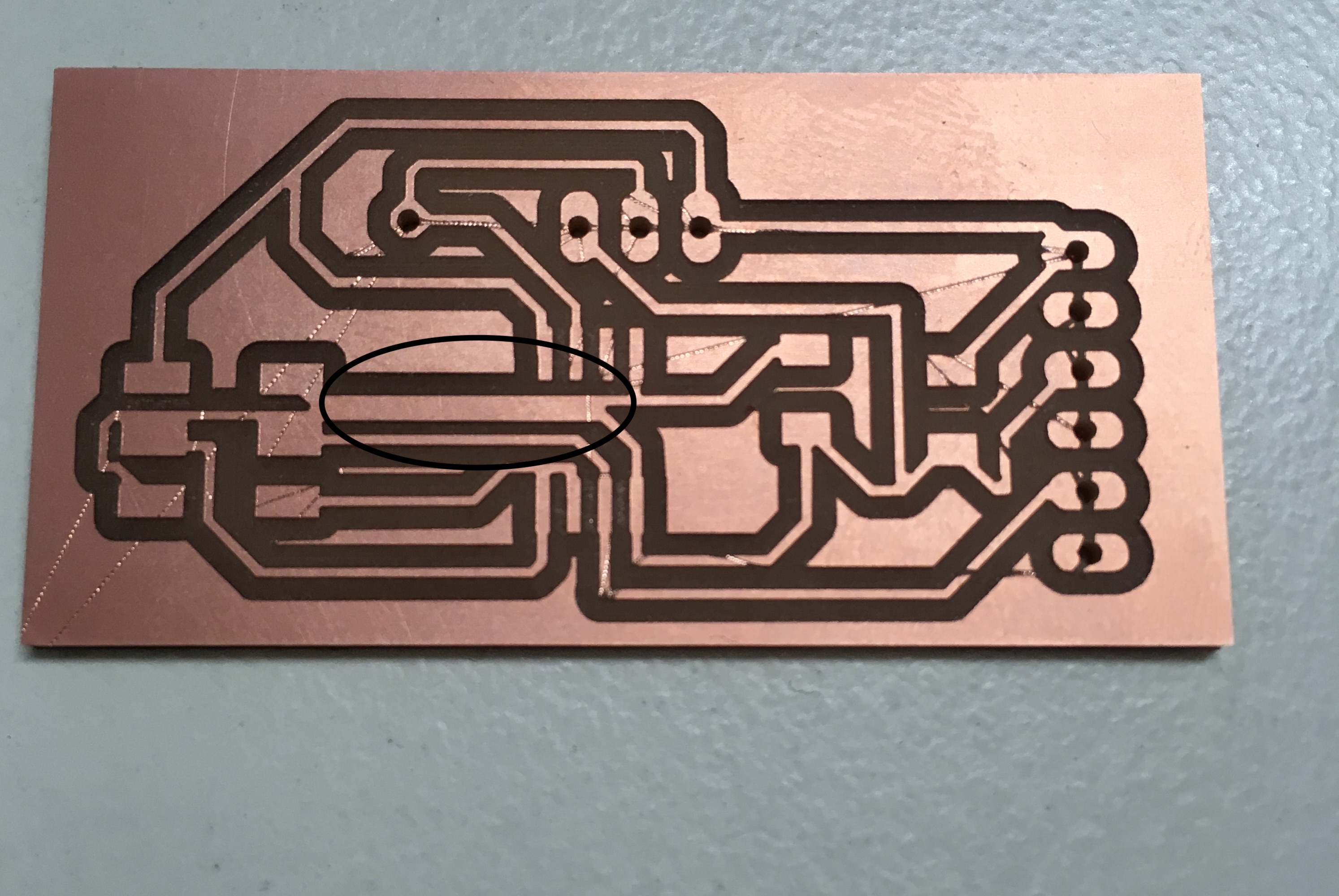
So I have milled with a single layer board and I haven't had this problem:
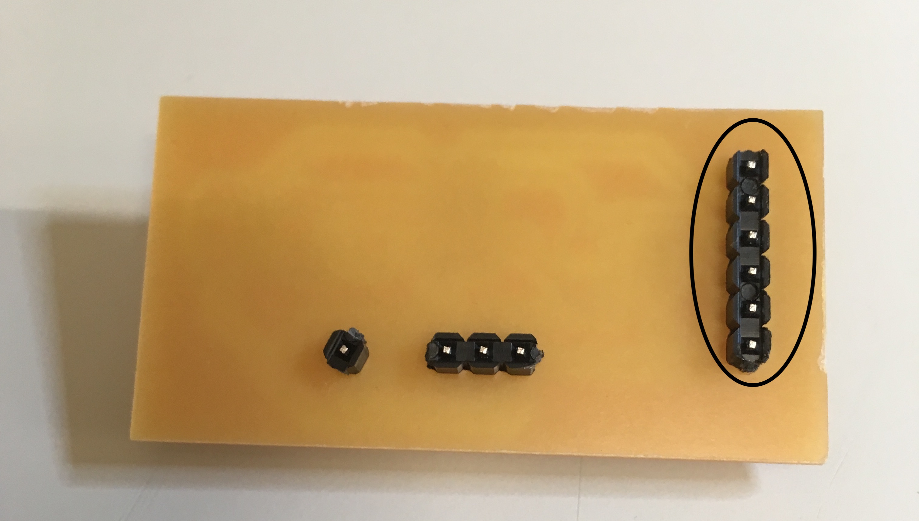 but I have set the jog height in the toolpath in 0 and not with the default value 2 so the tip of the machine has scratchied my trace removing the copper strate.
So the process of flashing my board isn't good and I' ve decided to put in stand by this board and do another sensor board
but I have set the jog height in the toolpath in 0 and not with the default value 2 so the tip of the machine has scratchied my trace removing the copper strate.
So the process of flashing my board isn't good and I' ve decided to put in stand by this board and do another sensor board
Sensor sonar
Another sensor useful for my final project is the sonar: the board is similar to the pyroelectrical one but the sensor sonar has 4 pin linked to the board: the design of this board is similar than the pyroelectric one.
the revision of python file
I use the code similar to neil' one but I have had to correct some line of the code cause I have the new version of python and the code that I have used is programmed in a older version of it
from tkinter import *
instead of
from Tkinter import *
I also have done an error beacuse I try to launch the python file with the code used in electronic design week
python file.py <name_serial port> <baudrate>
but to launch it in this case I have to write only the name file.py and the serialport without the baudrate:
writing the code in this way I launch the sensor and read the value of it in the serial interface:
IMG_5896 from Marco Cialone on Vimeo.
Probing my sensor pin signal
Considering that in the design of the board of the pyroeletrical sensor I've exposed the pin linked to the pin out of the sensors I have decided to redo this board :
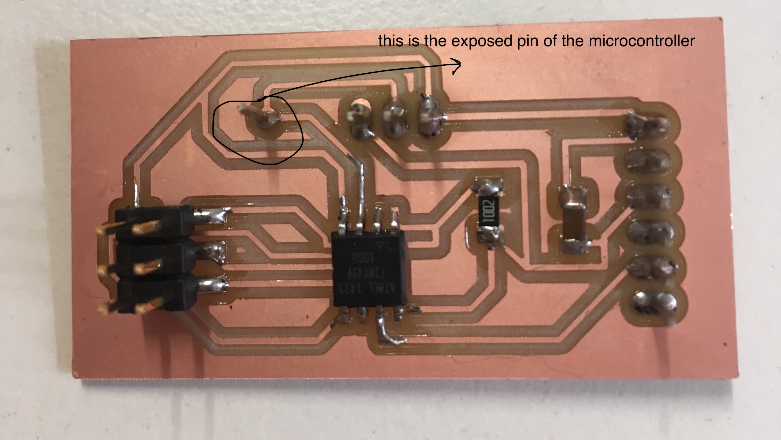 :
so I have probed this pin and the output visibile in the oscilloscope is the yellow line:
:
so I have probed this pin and the output visibile in the oscilloscope is the yellow line:
IMG_6170 from Marco Cialone on Vimeo.