Project Development
Questions about final project
What does it do?
My final Project is a machine which removes the leaves from the olives or something that has the leaves
Who’s done what beforehand?
In the web there are some example of this machine but they working is different: they haven't a sensor which activates the fan motor when we put the olives from the top od the machine.
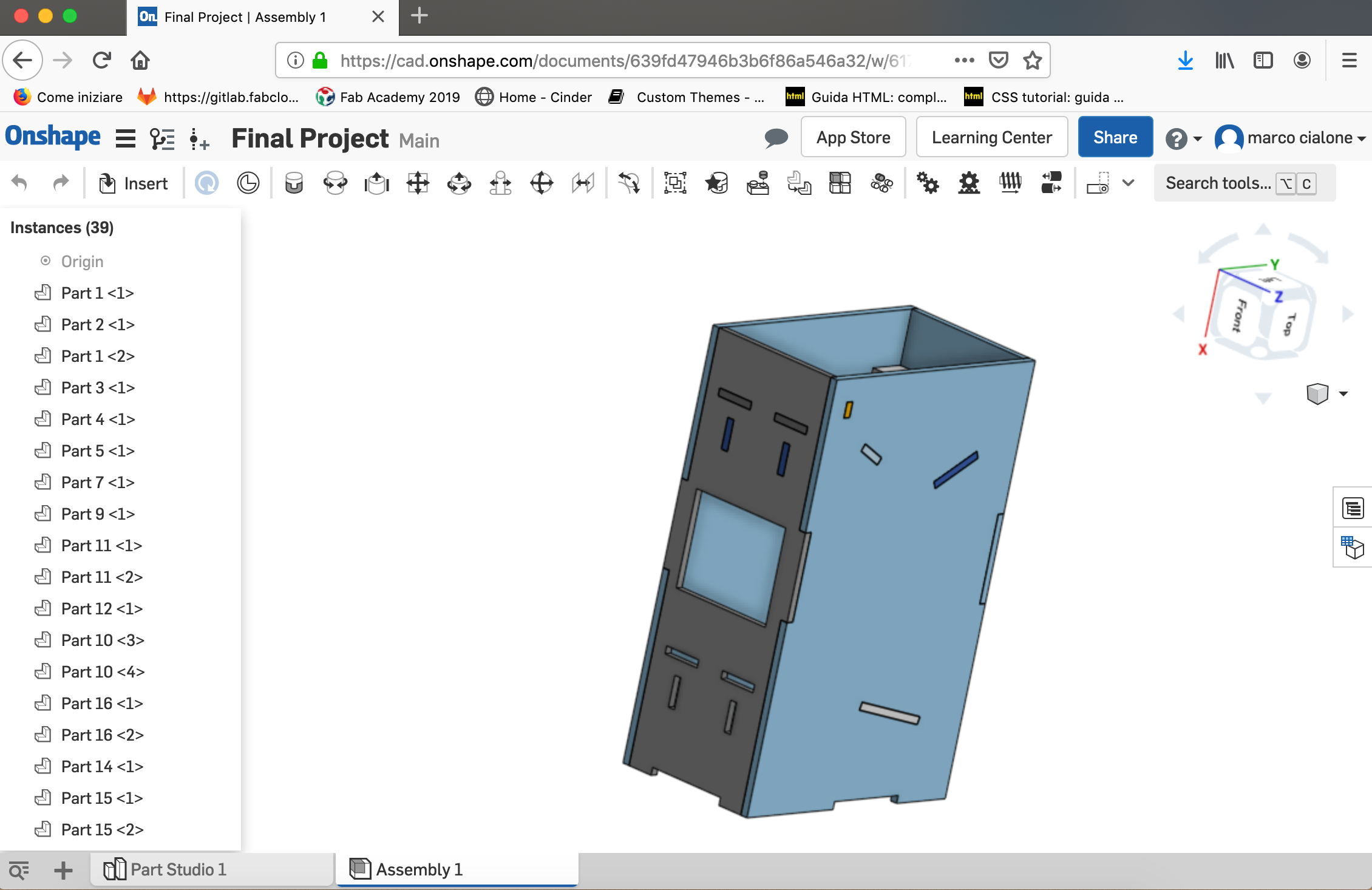
What did you design?
I've designed the structure of the machine and the internal bar done with the shopbot,the fan,the support for the fan and board, and at the end the box which contain the electronics components done with the laser cutter
What materials and components were used?
I've used the wood for the structure of the machine and the PLA material for the 3D printing.
Where did they come from?
Our fab lab has bought from the web and the shop if the city.
How much did they cost?
I have done the BOM (for the whole final project):
| component | quantity | vendor | price |
|---|---|---|---|
| 3d printing material | x5 | my work | 15$ |
| OSB table | x2 | website | 30$ |
| pcb board | x1 | website | |
| electronic component | website | 3$ | |
| sonar sensor | x1 | website | 2$ |
| lcd display | x1 | website | 3$ |
| load cell | x1 | website | |
| motor dc | x1 | website | 15.95$ |
What parts and systems were made?
Hardware: the wiring of the input and output device (in my case a sensor and a display) Software: I have to controll the state of my motor: when I put the olives the fan must turn in order to remove the leaves
What processes were used?
the schedule included in mt project are this:
- CAD and 3D printing
- Computer controlled machine
- electronic design
- embeeded programming
- input device
- output device
What questions were answered?
When I have the idea of this project I think that could be hard to link the wire in a box of the machine.
How was it evaluated?
my project could be evaluated like a prototype and if it will work I am going to add more function in it.
What are the implications?
I want to do an interface for the future in order to could see the state of the motor, and the emergency stop
presentation png
click here to see the image bigger
CAD and 3D printing
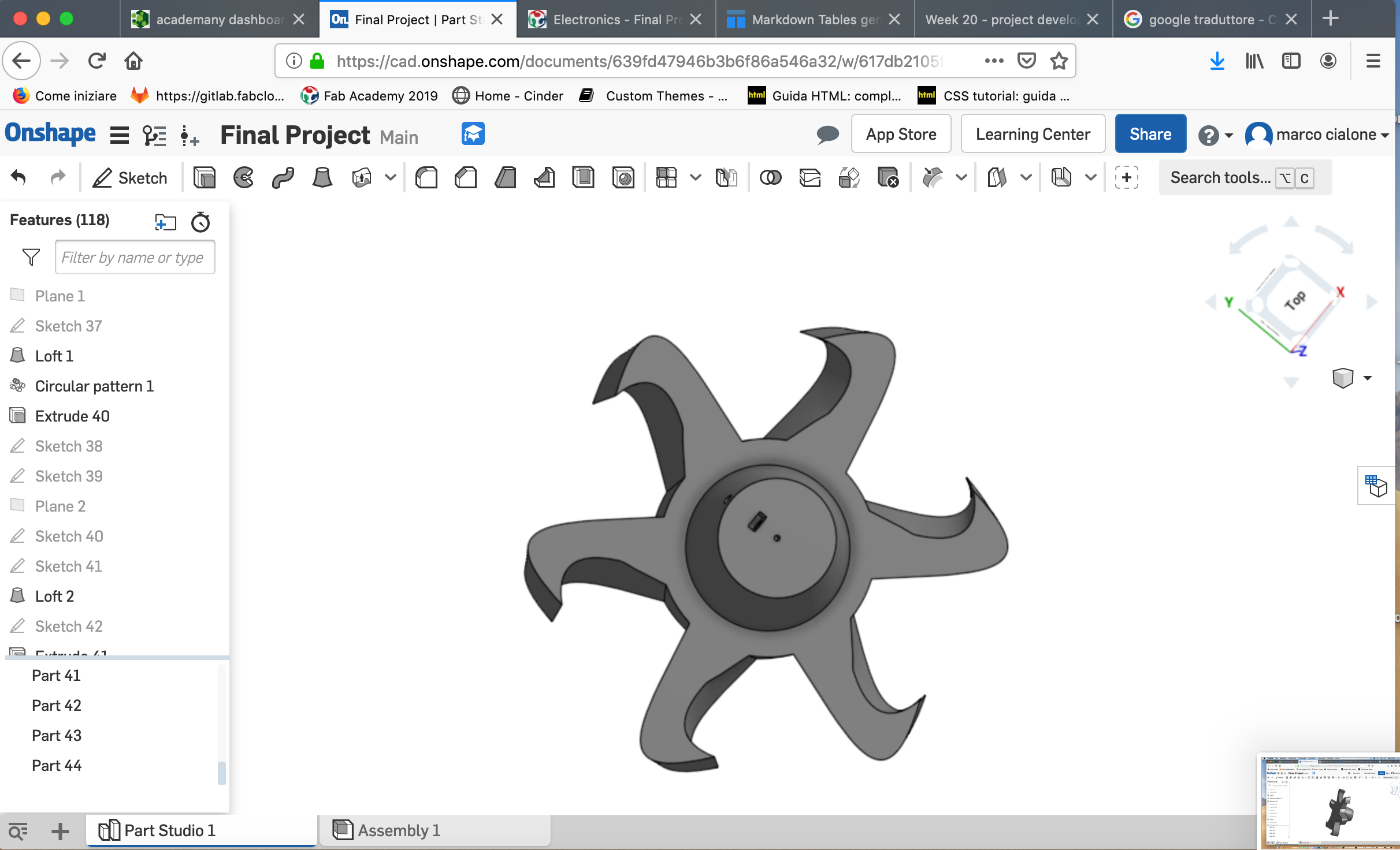
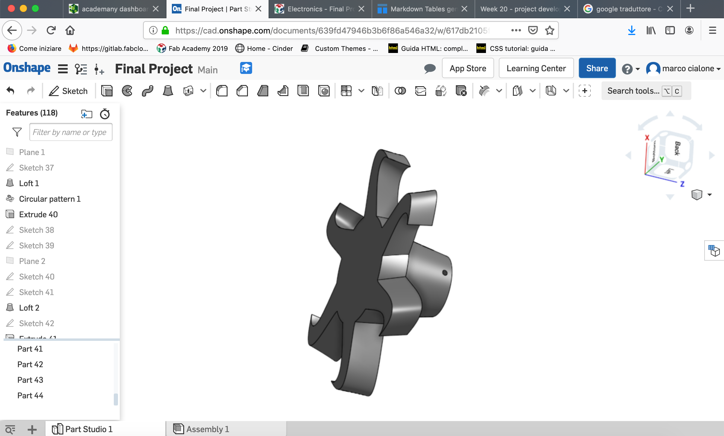
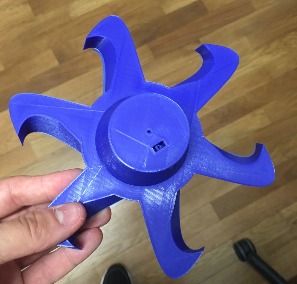
In my project there is a dc motor which makes it turn a fan: fortunately I've already tried to design it in the week of 3D printing but then I've modified it because before I haven't done the space to put the pin motor:
the model is visible here:
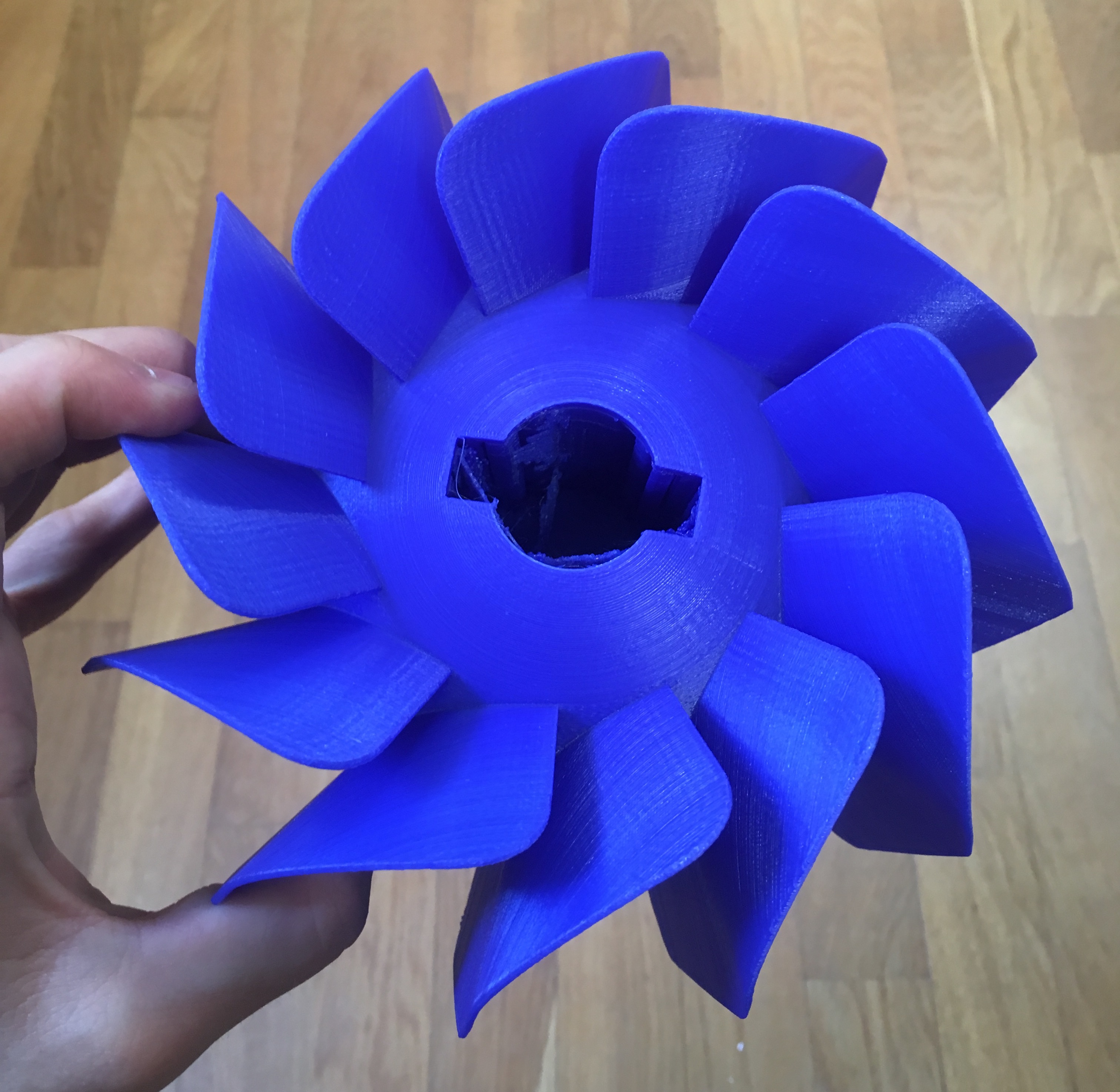
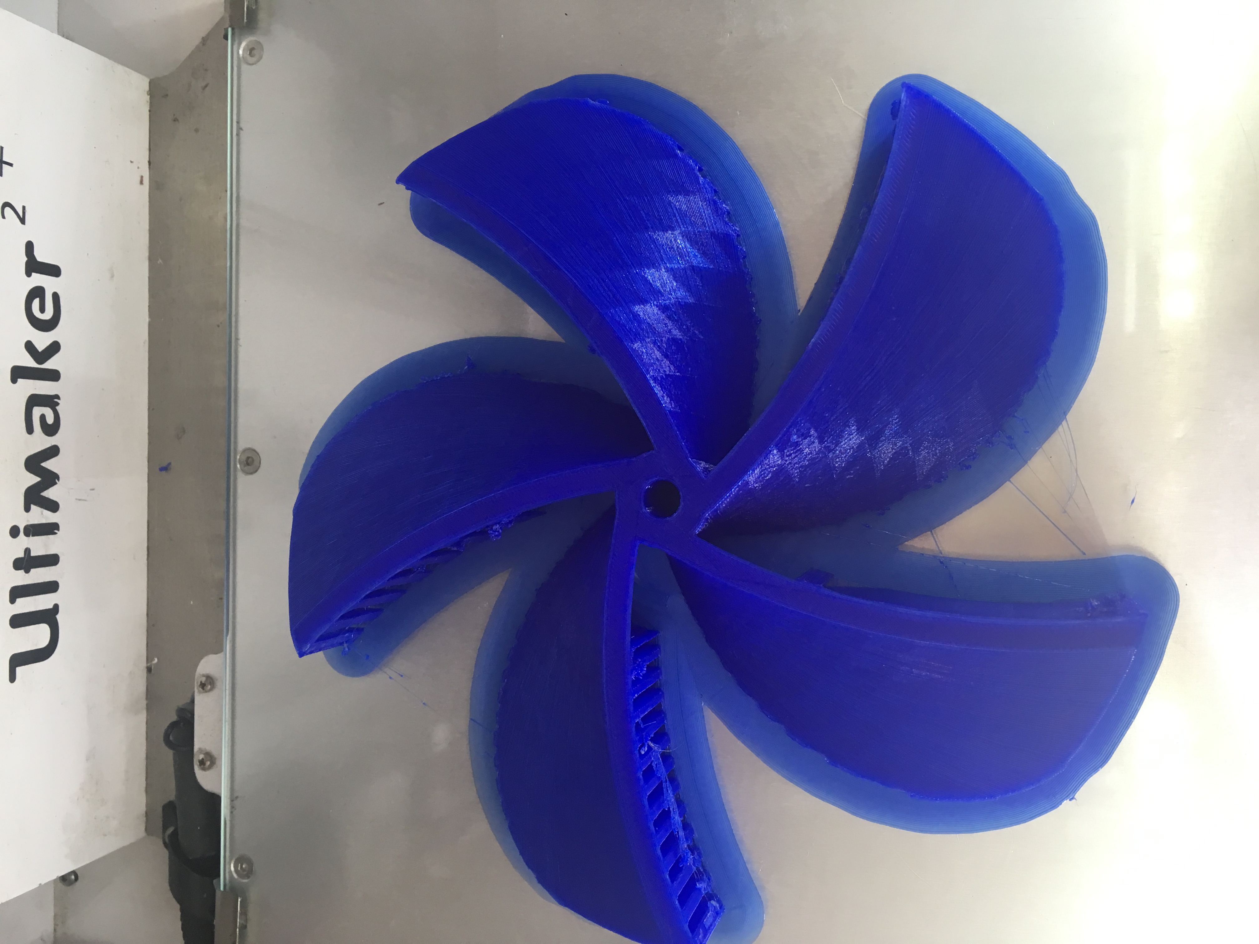
this fan is not good for the use that I am going to do: to solve this problem I've printed a fan designed in openscad (can you see it in the week of CAD):
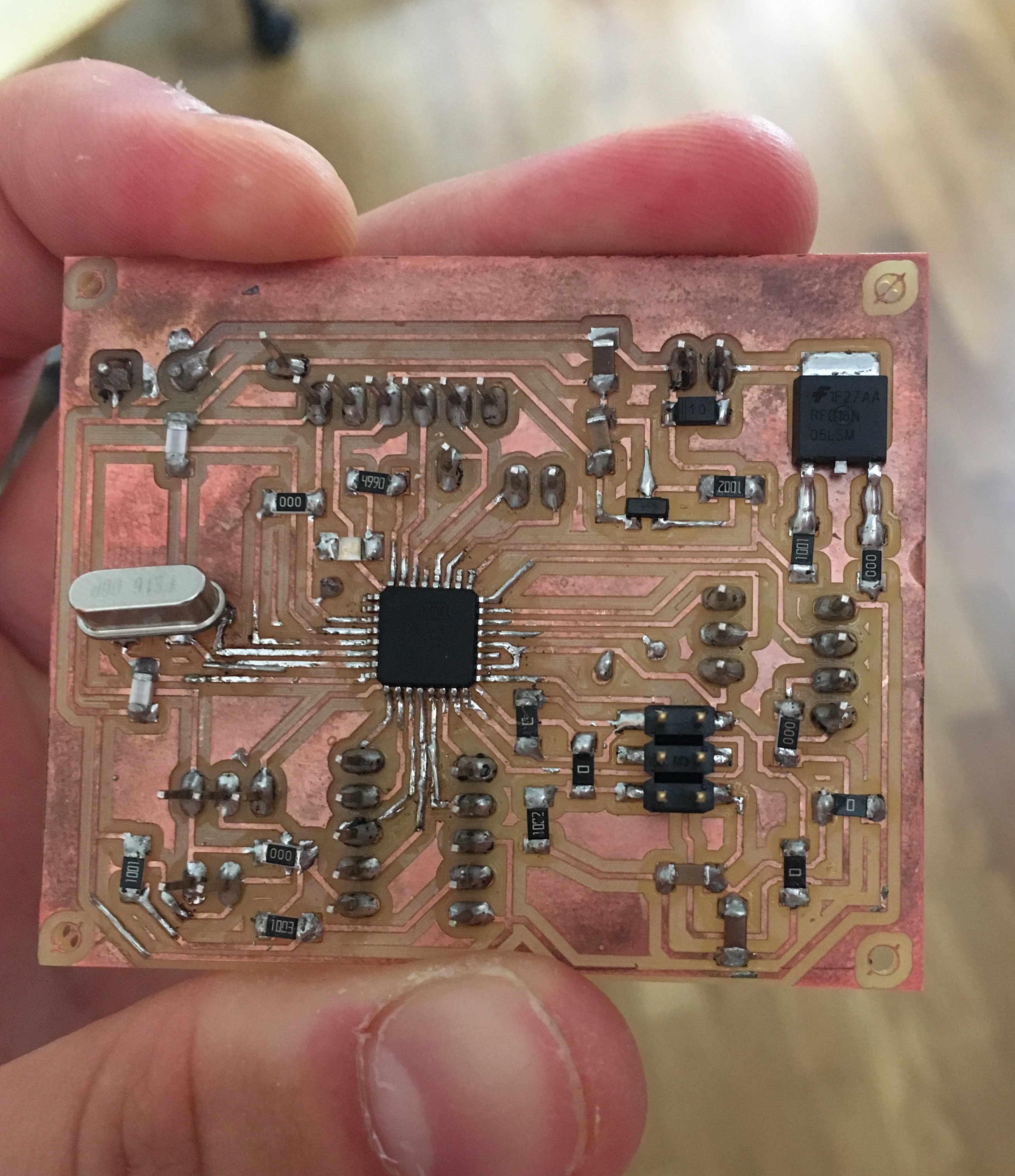
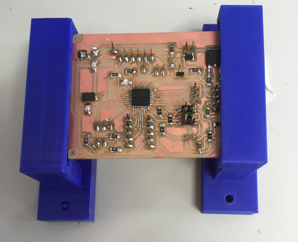
Electronic production for my final
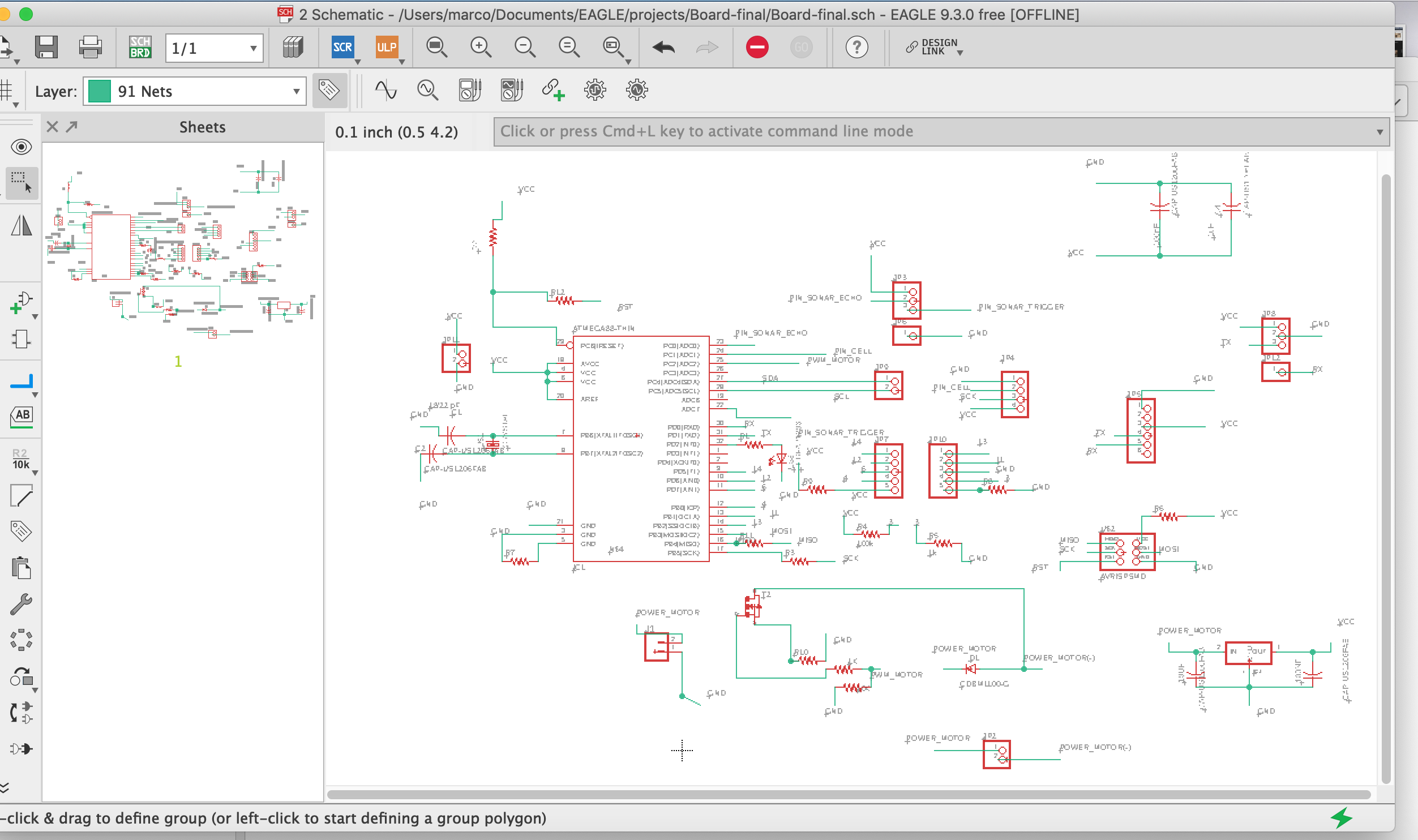
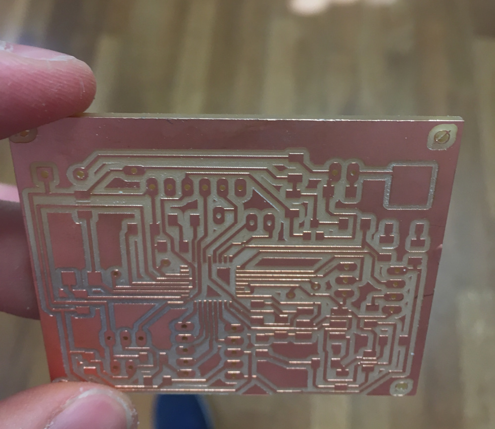
the day before the presentation I have only designed the board for my project but not milled it : I have simulate my schematic with an arduino and the wire linked to a breadboard.
the schematic and the board are this:
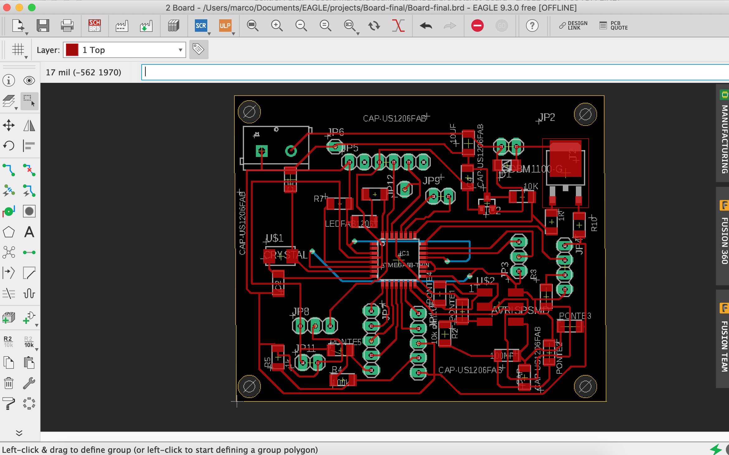
the Bill of Material:
| component | value | library |
|---|---|---|
| R1 | 1k | fab library |
| R2 | 100k | fab library |
| R3 | 10k | fab library |
| Cristal | 16 Mhz | crystal |
| Capacitor1 | 18/22 pF | fab library |
| Capacitor2 | 1uF | fab library |
| Capacitor3 | 100nF | fab library |
| voltage regulator | 12v to 5v | fab library |
| led | fab library | |
| ATmega328P | fab library(ATMEGA88-THIN package) | |
| transistor npn | fab library | |
| pin header | ... | pinhead |
| my board | ... | ... |
embeeded programming and final working
the programm that I have done, should read ,by a sensor, the distance between the two side : in that way if the distance detected is less that this fix distance (so the olives are coming into the machine) the motor turn on in order to throw the leaf out; my programm also write on a display the state of the motor.
// ---------------------------------------------------------------------------
// Example NewPing library sketch that does a ping about 20 times per second.
// ---------------------------------------------------------------------------

#include <NewPing.h>
#include <LiquidCrystal.h>
// initialize the library by associating any needed LCD interface pin
// with the arduino pin number it is connected to
const int rs = 7, en = 8, d4=9, d5 = 10, d6 = 11, d7 = 12;
LiquidCrystal lcd(rs, en, d4, d5, d6, d7);
#define TRIGGER_PIN  A1  // Arduino pin tied to trigger pin on the ultrasonic sensor.
#define ECHO_PIN     A0  // Arduino pin tied to echo pin on the ultrasonic sensor.
#define MAX_DISTANCE 200 // Maximum distance we want to ping for (in centimeters). Maximum sensor distance is rated at 400-500cm.
#define pin_motor 6
NewPing sonar(TRIGGER_PIN, ECHO_PIN, MAX_DISTANCE); // NewPing setup of pins and maximum distance.
int valore_sonar ;
int i;
int stato_precedente;

void setup() {
Serial.begin(115200);// Open serial monitor at 115200 baud to see ping results.
lcd.begin(16, 2);
lcd.setCursor(0, 0);
pinMode(pin_motor,OUTPUT);
analogWrite(pin_motor,0);
}
void loop() {
delay(200);                     // Wait 50ms between pings (about 20 pings/sec). 29ms should be the shortest delay between pings.
sonar.ping_cm();

if(sonar.ping_cm()<40 && stato_precedente==0){

Serial.print(sonar.ping_cm()); // Send ping, get distance in cm and print result (0 = outside set distance range)
Serial.println("cm");
Serial.println("motore:on");
lcd.setCursor(0, 0);
delay(50);
lcd.print("motore:on");


for(i=0;i<145;i++){
analogWrite(pin_motor,i);
delay(15);
}
analogWrite(pin_motor,145);
stato_precedente=145;
delay(1000);
}
else if (sonar.ping_cm()<40 && stato_precedente==145){
Serial.print(sonar.ping_cm()); // Send ping, get distance in cm and print result (0 = outside set distance range)
Serial.println("cm");
Serial.println("motore: on");
lcd.setCursor(0, 0);
delay(100);
lcd.print("motore:on ");

analogWrite(pin_motor,145);
delay(1000);
}

else if(sonar.ping_cm()>=40 && stato_precedente==0){

Serial.print(sonar.ping_cm()); // Send ping, get distance in cm and print result (0 = outside set distance range)
Serial.println("cm");
Serial.println("motore:off");
lcd.setCursor(0, 0);
delay(100);
lcd.print("motore:off ");
analogWrite(pin_motor,0);
stato_precedente=0;

}
else if(sonar.ping_cm()>=40 && stato_precedente==145){

Serial.print(sonar.ping_cm()); // Send ping, get distance in cm and print result (0 = outside set distance range)
Serial.println("cm");
Serial.println("motore:off");
lcd.setCursor(0, 0);
delay(100);
lcd.print("motore:off ");
for(i=145;i>0;i--){
analogWrite(pin_motor,i);
delay(15);
}
analogWrite(pin_motor,0);
stato_precedente=0;
}
}
Laser cutter
with the laser cutter I've done the electronics cover:
Shopbot work
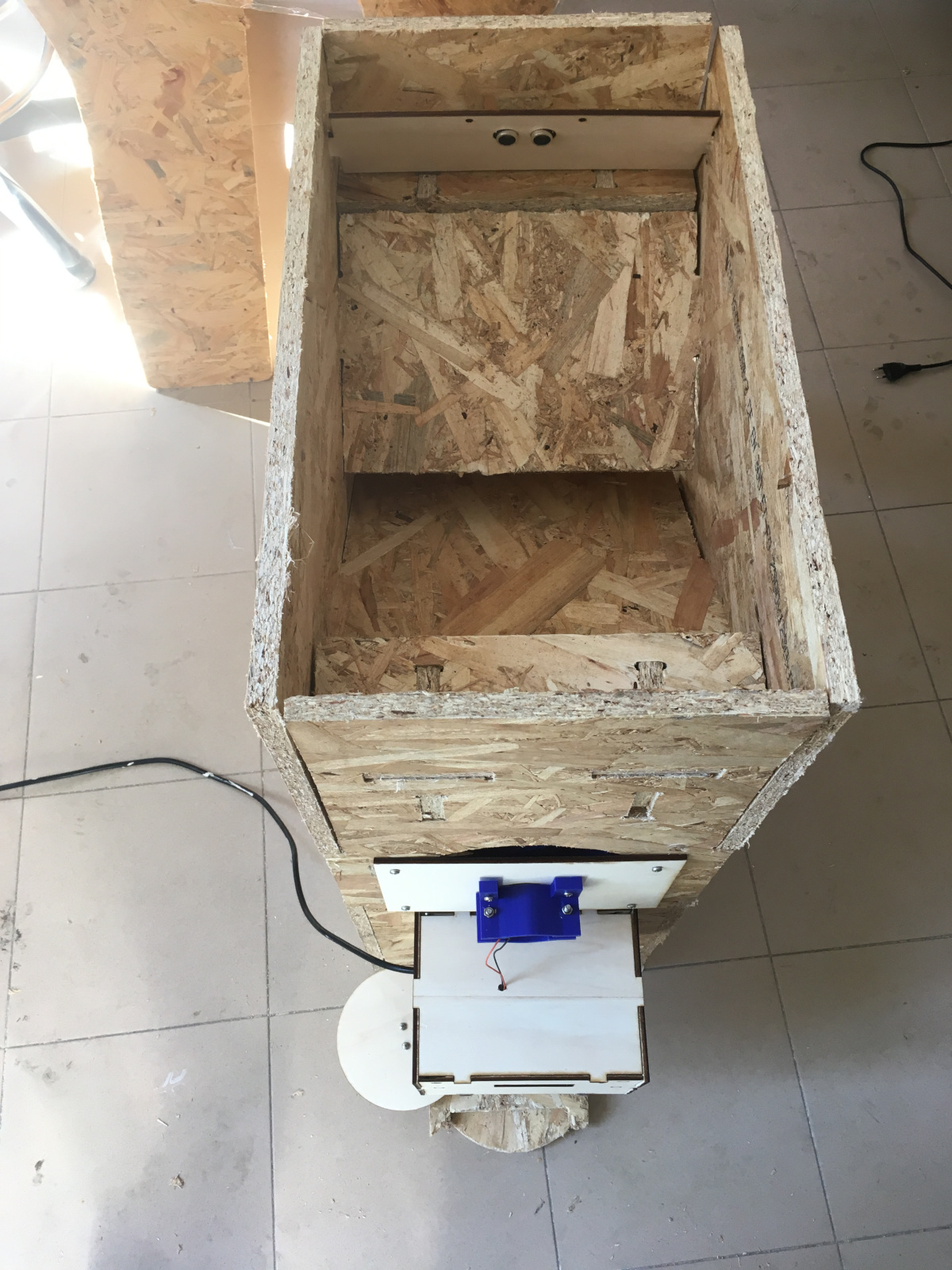
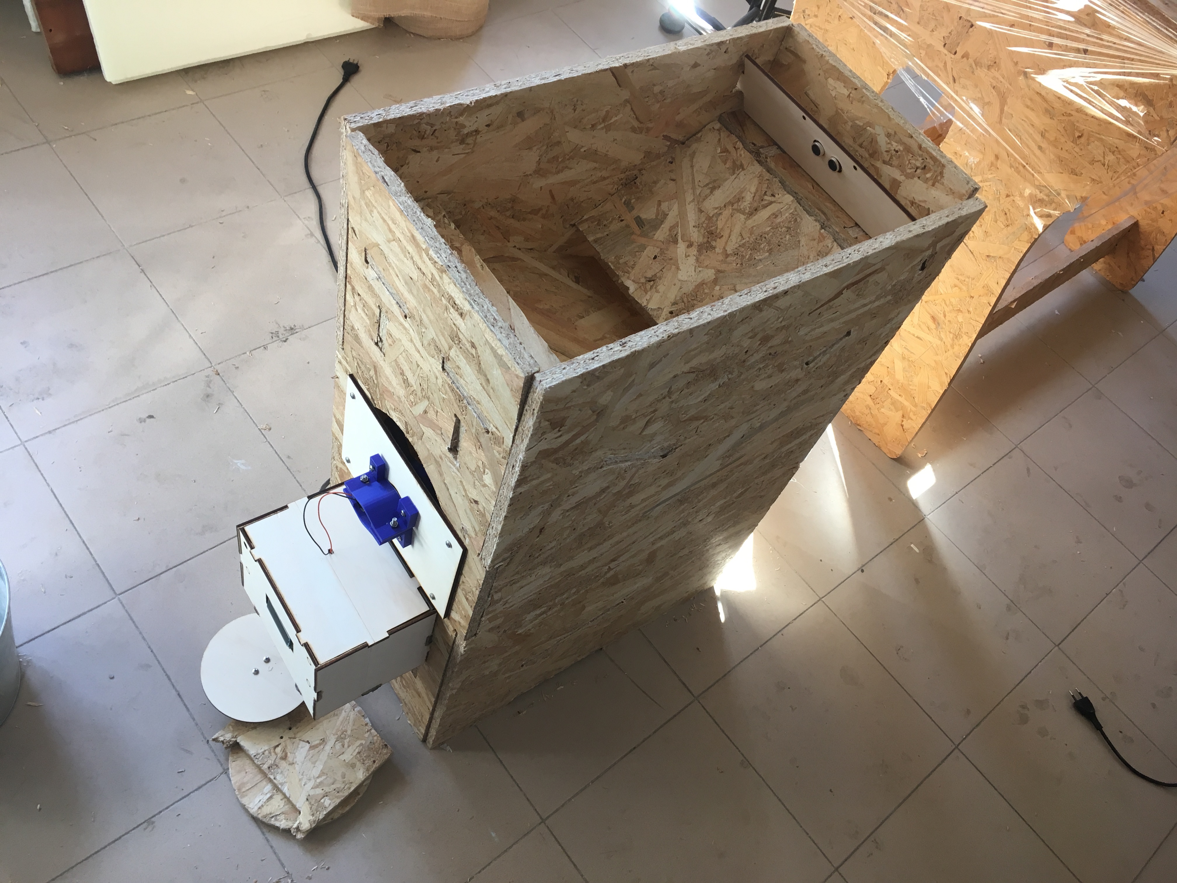
With the shopbot I've done the whole structure of the machine (the external part and the internal bar where the olives slip on):
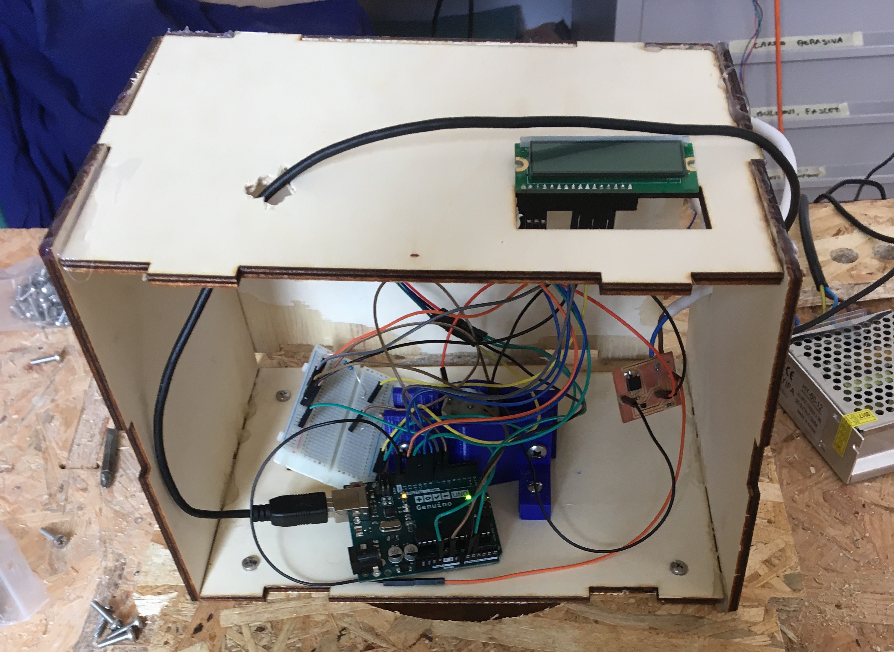
main problem of the system
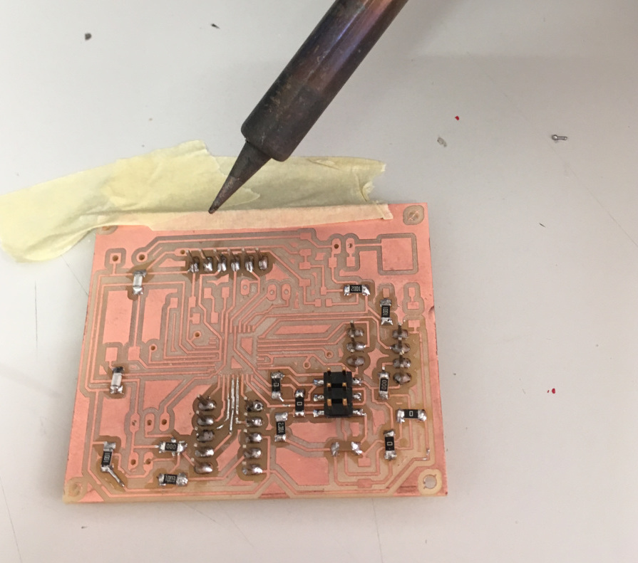
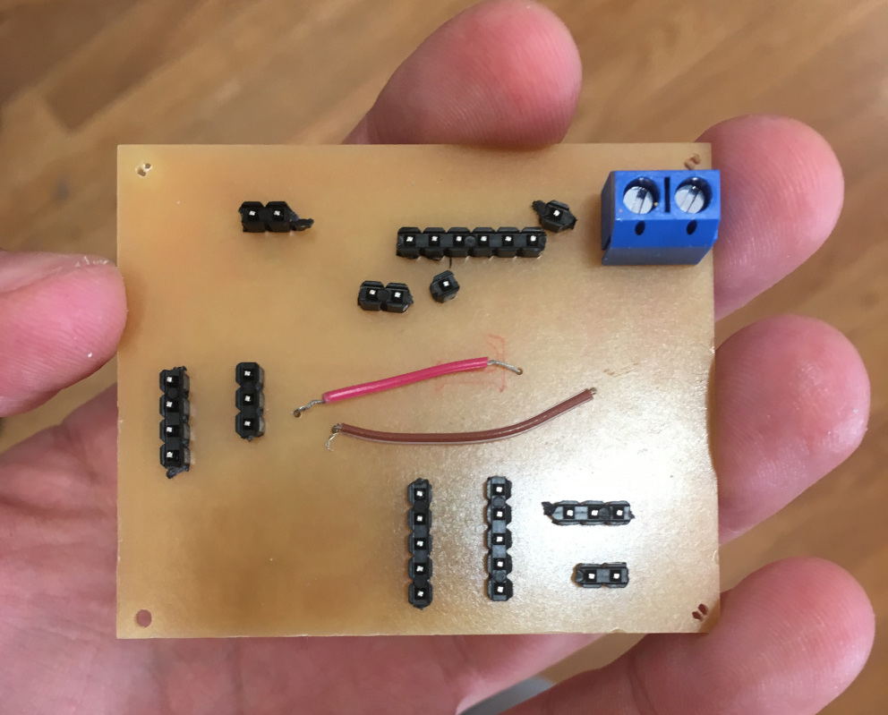
Unfortunatly when I've fixed all the component an do the whole strucutre It didn't work because some linking (maybe those of the breadboard) are disconnected: so the problem was about the package of the electronic linking and the unfixed microcontroller:
so I've decided to re-do the box of the elctronics in a different way and the support of the board that I am going to mill. But though the board have worked ,the machine wouldn't work anyway because I haven't done a good support for the fan: so I've decided to redone it too..
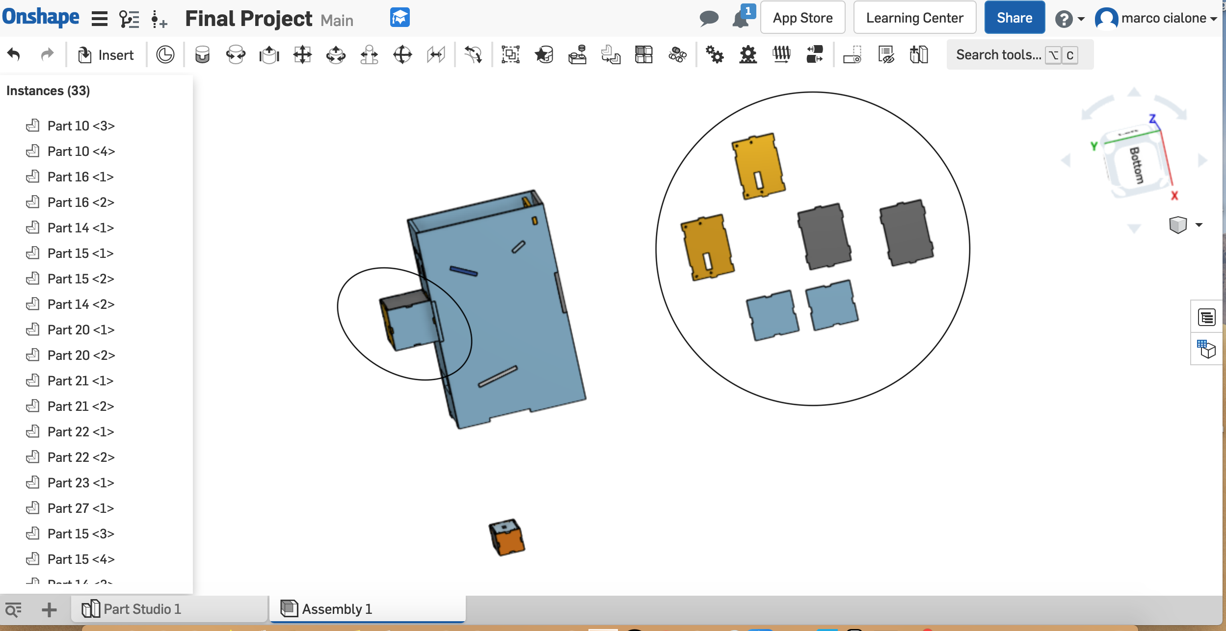
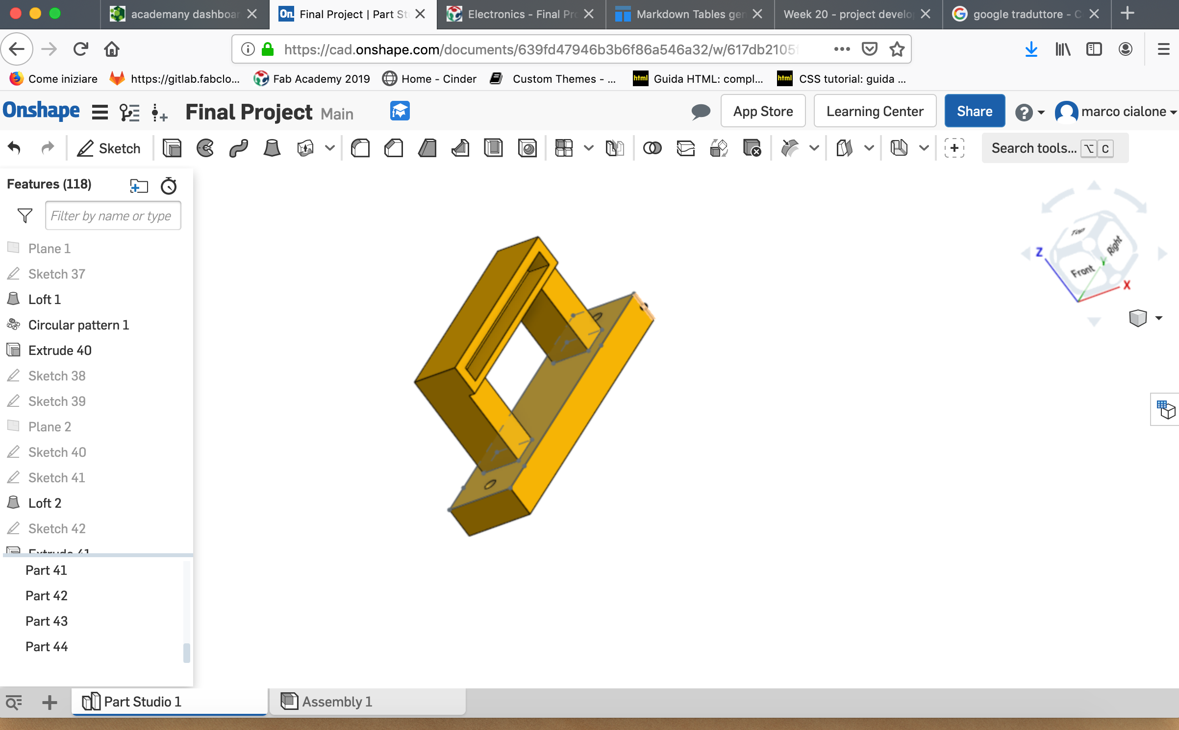
problem solving
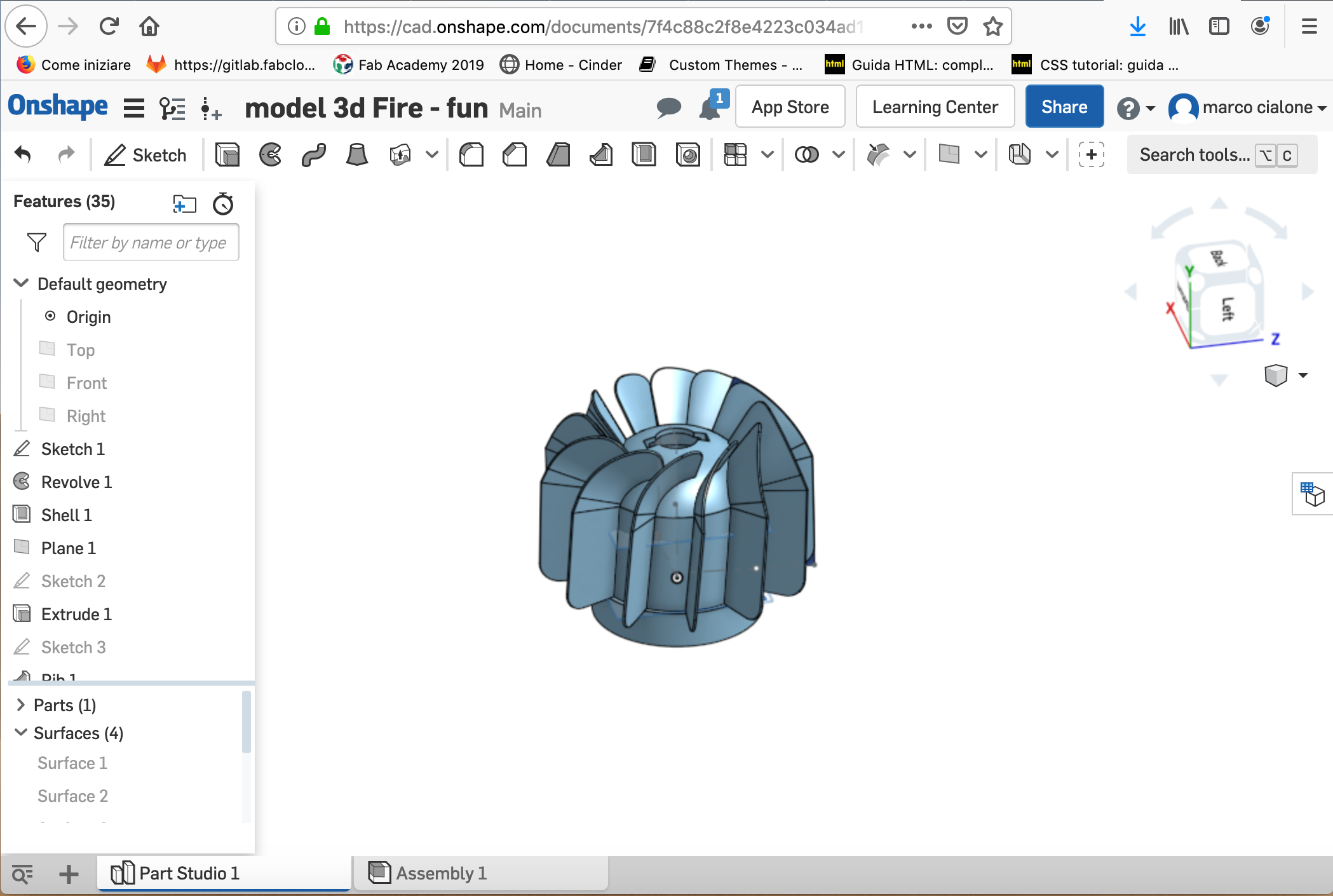
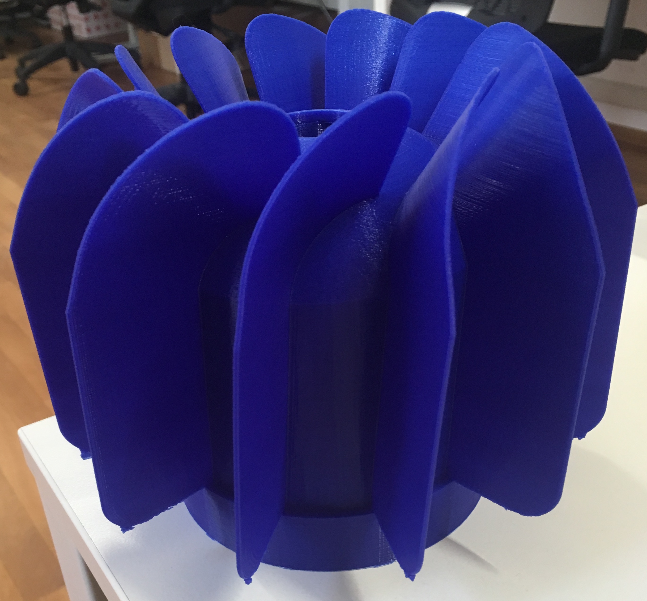
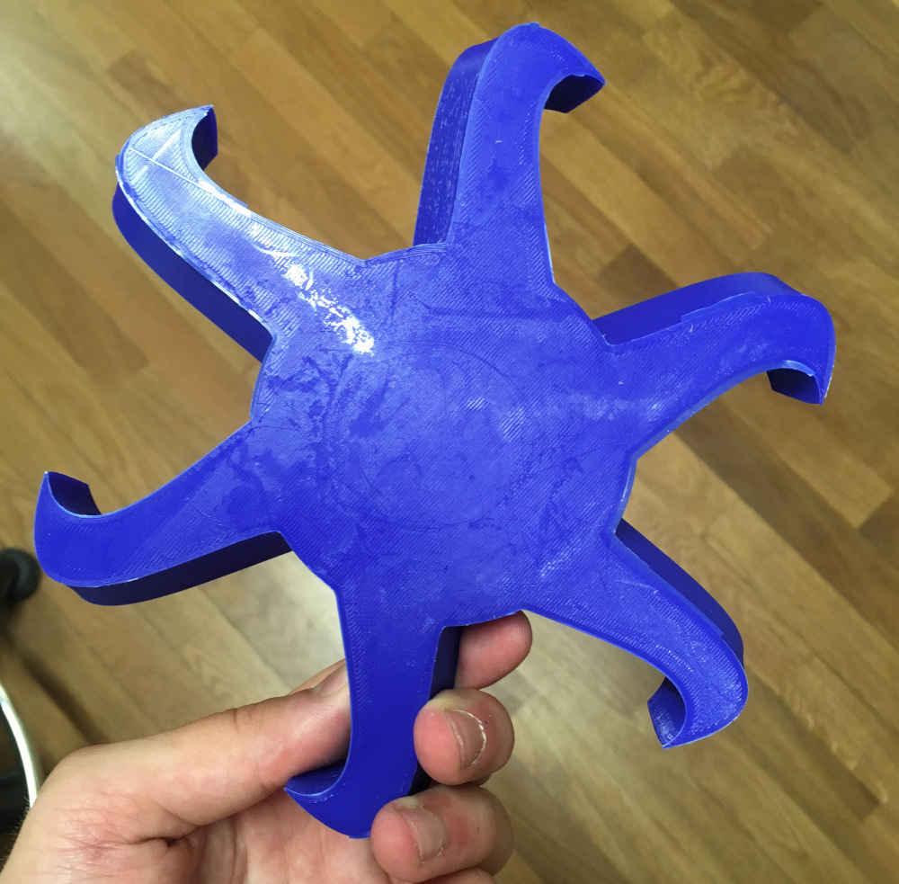
To have a better package of my machine I've decided to fix the board with a support : i've decided to move the box which contain the electronic component and to do 2 lateral bar where I can fix the support of the motor ; at the end I've done an other fan with the space where I can join it with the motor without doing a support between the fan and motor because It is more difficult and in my opinion isn't a good work. In fact I've tried to do a support but I haven't had any effective result.
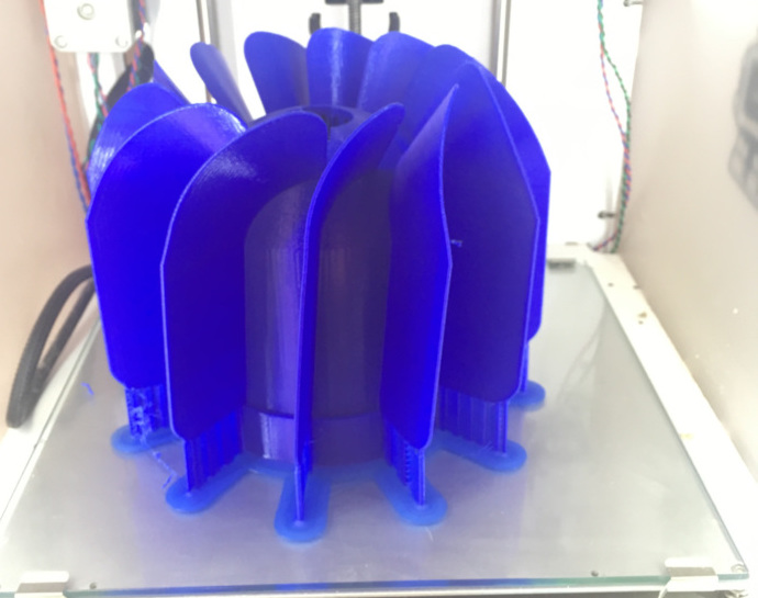
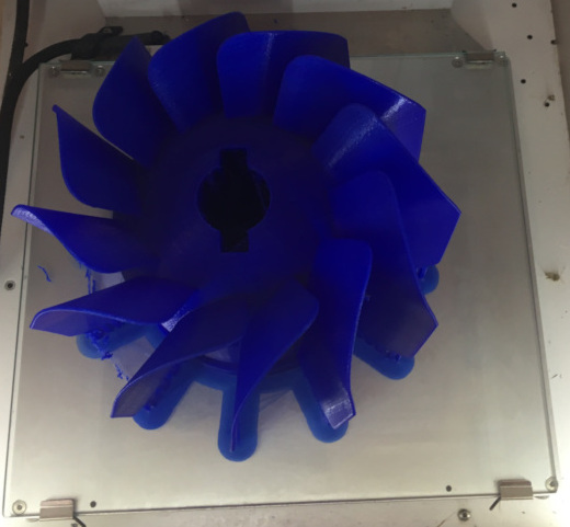
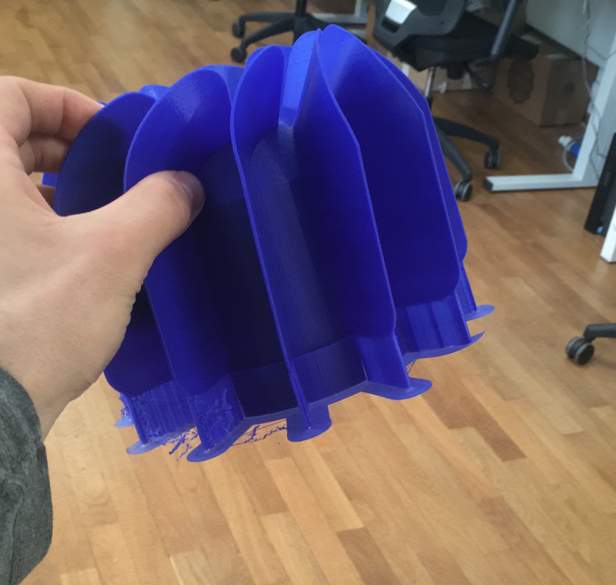
I've printed the fan of the on shape model and this is the result:
I've fixed my fan with the the motor:
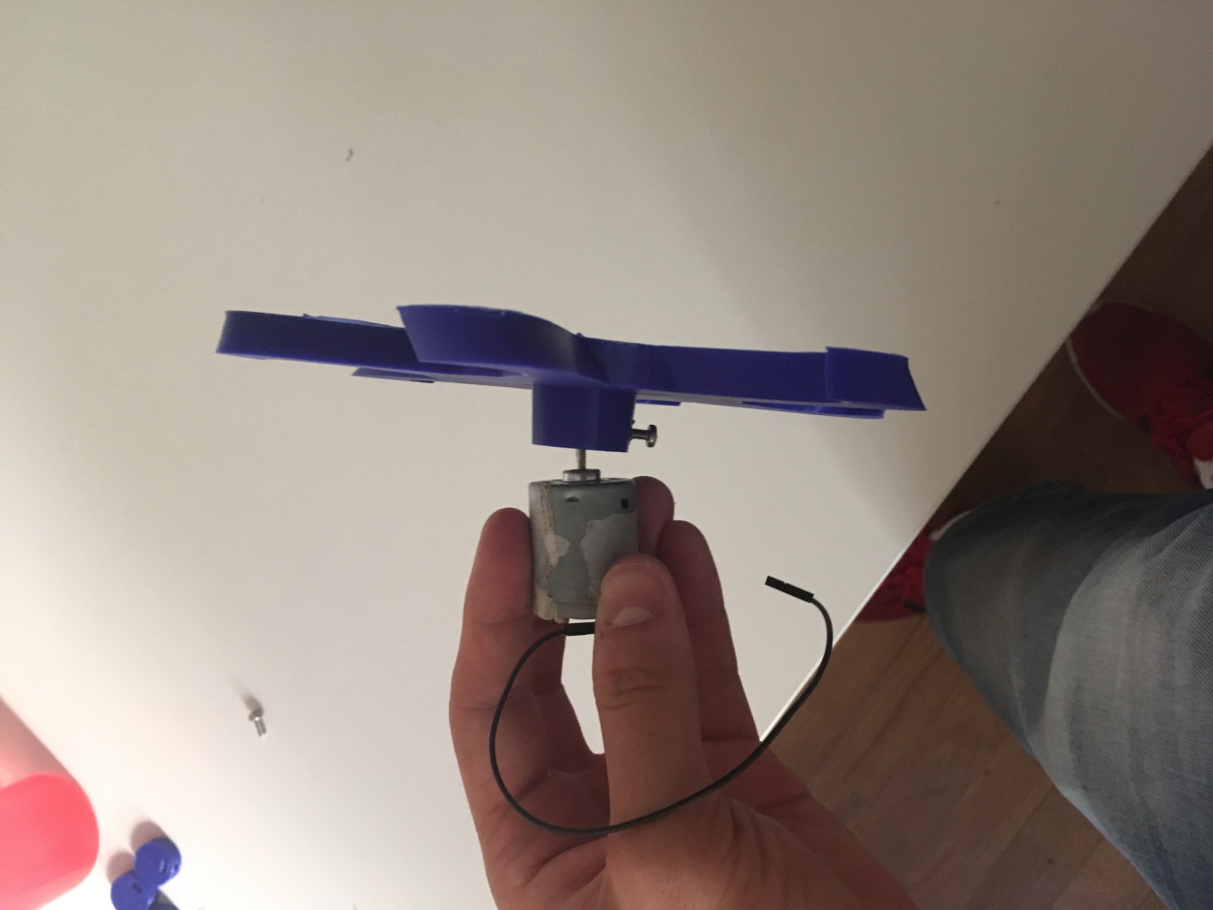
and then I've test the support and It is good
now I am going to do the box where I fix the support with the board : in the box I have to do the space for the every wires like in the other one done before.
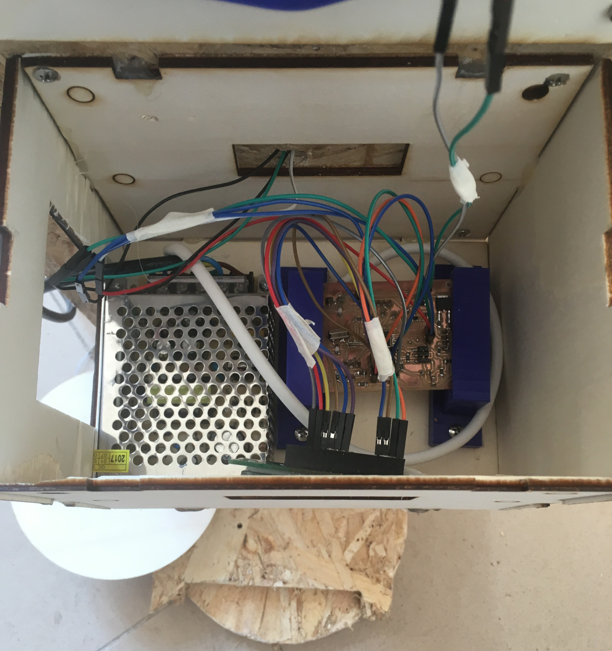
Better Packaging and complete project
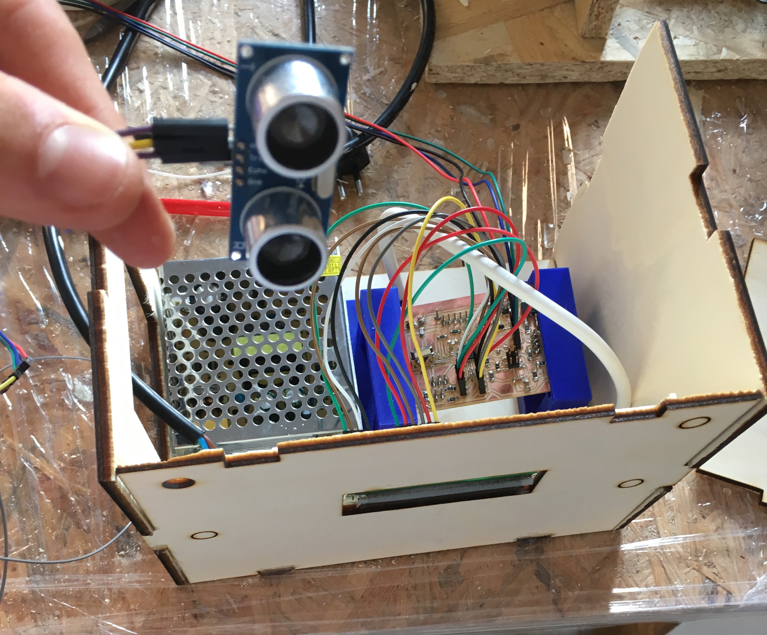
I've done a box where I've fixed my board with the support and where there is the 12V power supply that I've linked to my board in order to power it: like we can see,the packaging is better because now the board is fixed and the wire are more stable.
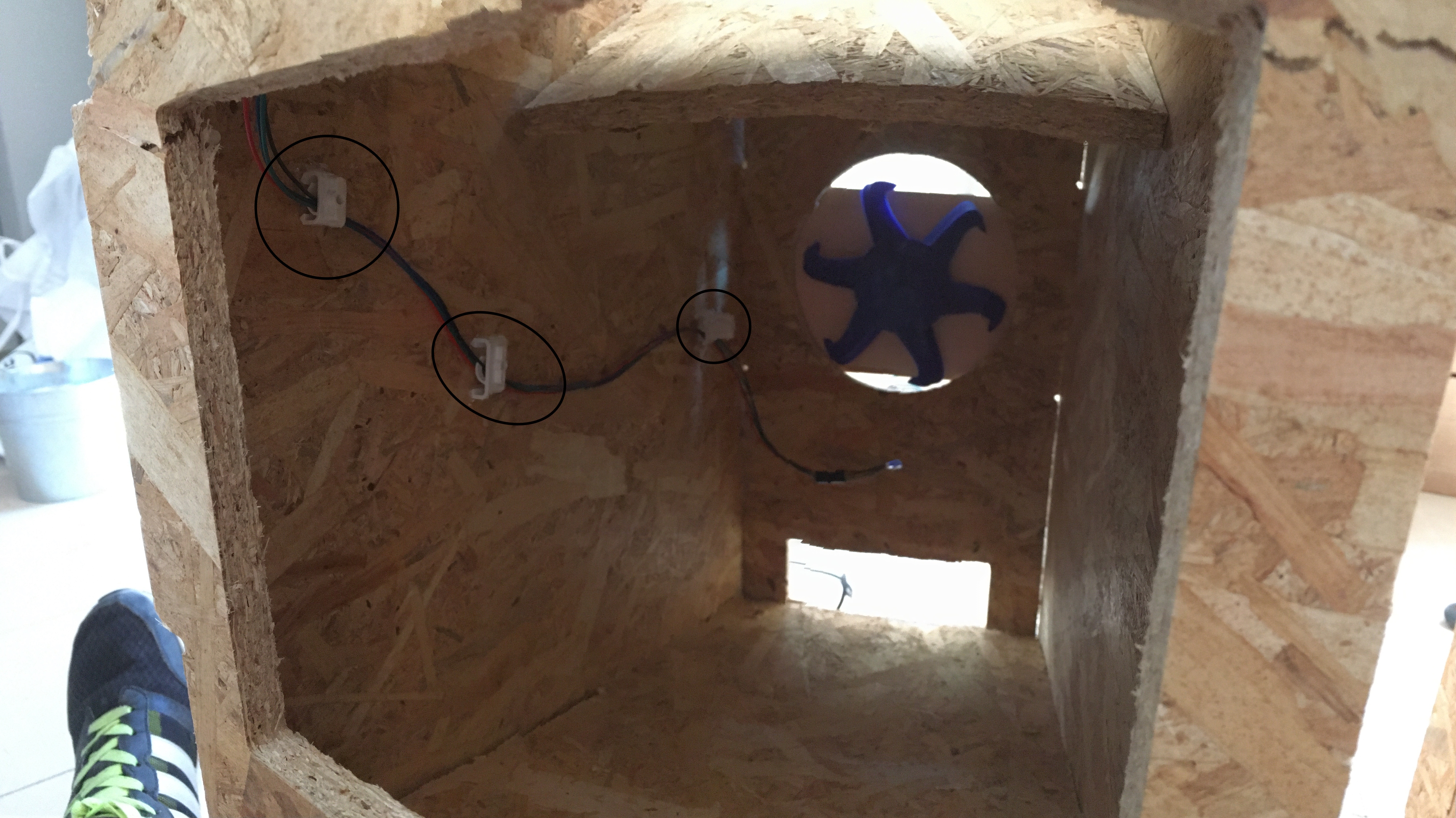
I've improved the connection of the wires inside the machine (the wires of the sonar): I've tightened them with three cable ties so they don't come off due to the fall of the olives:
the final packaging is this:
Future development
- Interface: in the future I would like continuing the project adding an interface using the bluethoot connection (I've exposed the pin in my board for a future connection).
- accurately misure of the load cell: I want to calibrate and program the load cell in order to weigh the olives well.
Final project Update presentation