16. Interface and application programming
This week was based on developing an interfacing a board and developing an interfacing user interface with computer and the group project was about comparing as many tool which can be used for the operation
Through the week
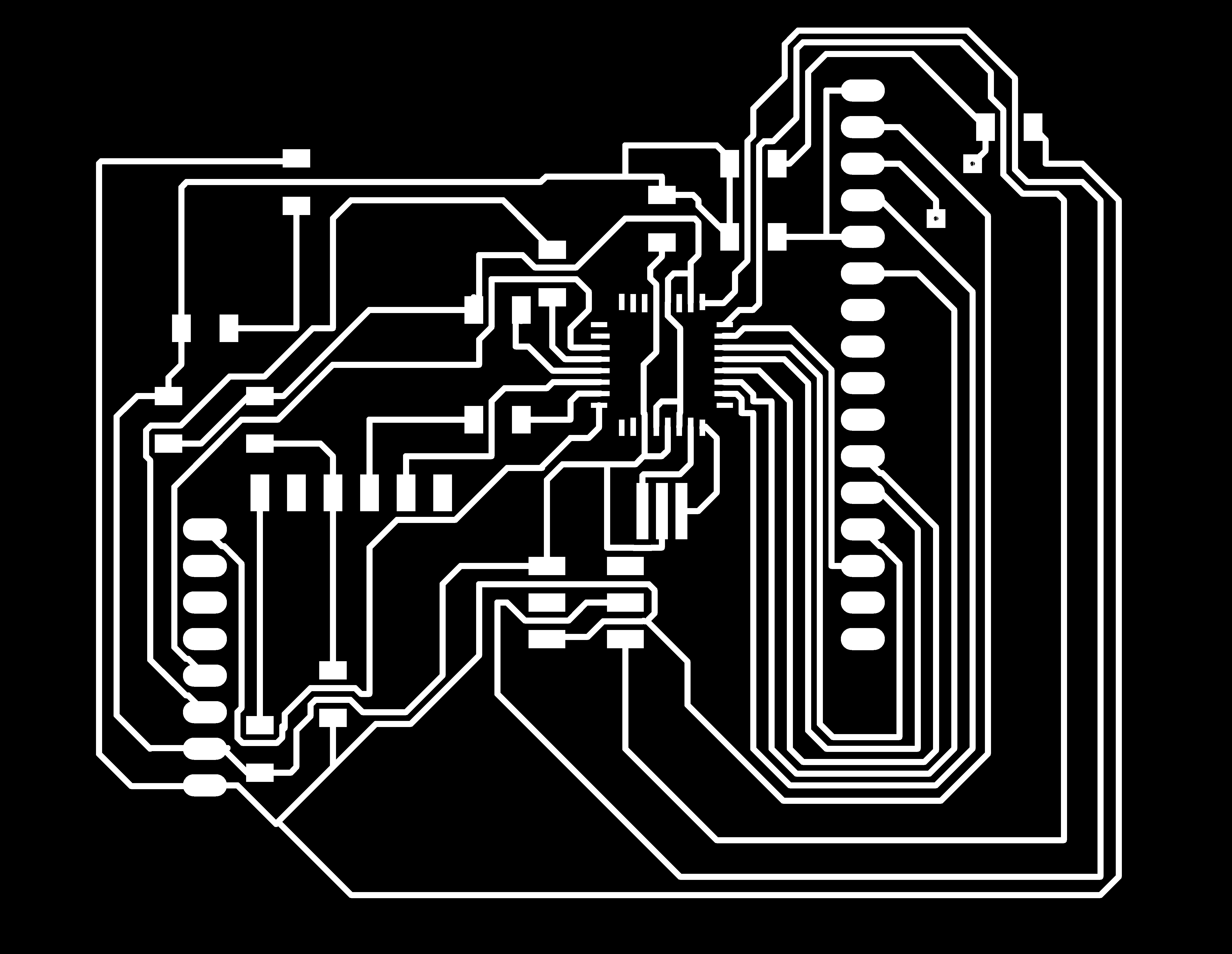
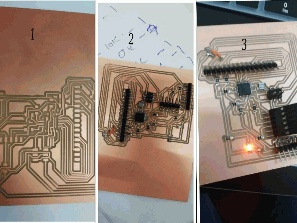
1.For this week i used the same board used in output week ie. the board which is connected to mpu6050 using i2c connection and programmed it to get y direction so as to send a serial data.
2.
3.
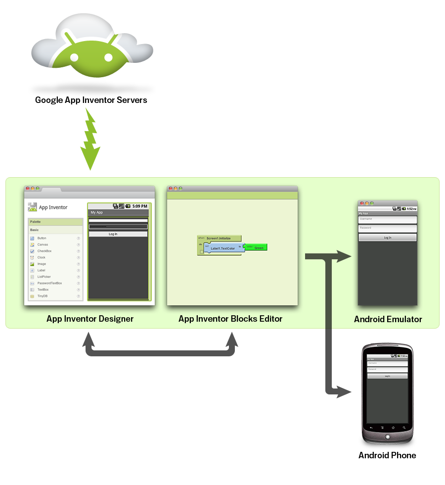
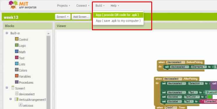
4.For using the interface I used MIT app inventor to identify the Y direction.
5.App Inventor for Android is an open-source web application originally provided by Google, and now maintained by the Massachusetts Institute of Technology (MIT). It allows newcomers to computer programming to create software applications for the Android operating system (OS). It uses a graphical interface, very similar to Scratch and the StarLogo TNG user interface, which allows users to drag-and-drop visual objects to create an application that can run on Android devices. In creating App Inventor, Google drew upon significant prior research in educational computing, as well as work done within Google on online development environments.[1] App Inventor and the projects on which it is based are informed by constructionist learning theories, which emphasizes that programming can be a vehicle for engaging powerful ideas through active learning. As such, it is part of an ongoing movement in computers and education that began with the work of Seymour Papert and the MIT Logo Group in the 1960s and has also manifested itself with Mitchel Resnick’s work on Lego Mindstorms and StarLogo.[1][2] MIT App Inventor is also supported with the Firebase Database extension. This allows people to store data on Google’s firebase
6.
7.After getting into the mit app inventor page,I found many option to build according to our need.
8.Basically we will be handling two modes.
(i)Designer mode (ii) blocks mode.

In the designer mind we can set the front sheet of the app.ie we can really design the needs we want,like buttons,colour,length, width,background,theme,etc
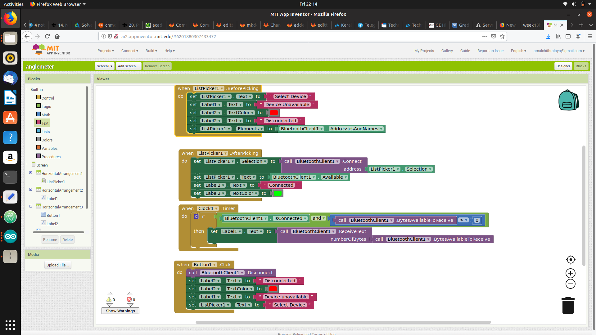
In the blocks mode we need code our app and make the design really working.
Actually on the left side there are option s which is in the shape of puzzles which made the mIT app really interesting.we need to select it right as per our need.
There I added the bluetooth connection and made the buttons all working.
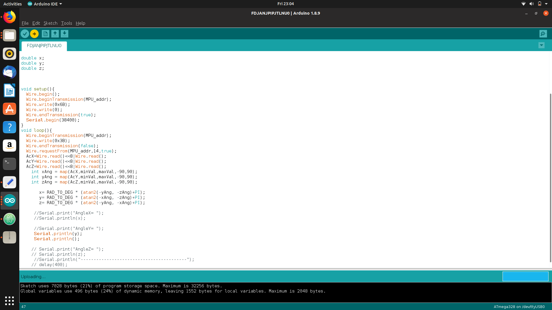
Then I programmed the board i2c enabled Slave board which i have made it during the networking week and connected to an mpu 6050(accelerometer/Gyro) and programmed according to display the “Y” axis .
PROGRAM
#include<Wire.h>
#include <SoftwareSerial.h>

const int MPU_addr=0x68;
int16_t AcX,AcY,AcZ,Tmp,GyX,GyY,GyZ;


int minVal=265;
int maxVal=402;

double x;
double y;
double z;


void setup(){
  Wire.begin();
  Wire.beginTransmission(MPU_addr);
  Wire.write(0x6B);
  Wire.endTransmission(true);
  Serial.begin(38400);
}
void loop(){
Wire.beginTransmission(MPU_addr);
Wire.write(0x3B);
Wire.endTransmission(false);
Wire.requestFrom(MPU_addr,14,true);
AcX=Wire.read()<<8|Wire.read();
AcY=Wire.read()<<8|Wire.read();
AcZ=Wire.read()<<8|Wire.read();
int xAng = map(AcX,minVal,maxVal,-90,90);
int yAng = map(AcY,minVal,maxVal,-90,90);
int zAng = map(AcZ,minVal,maxVal,-90,90);

x= RAD_TO_DEG * (atan2(-yAng, -zAng)+PI);
y= RAD_TO_DEG * (atan2(-xAng, -zAng)+PI);
z= RAD_TO_DEG * (atan2(-yAng, -xAng)+PI);

Serial.println(y);
}
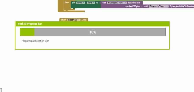
Then by using the option I generated the QR code apk file and downloaded the app on my phone
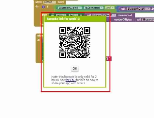
Then I generated the QR Code
QR CODE
After that I connected the serial out of the board with HC05 Bluetooth module .
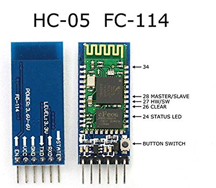
Then paired the device to mobile phone.
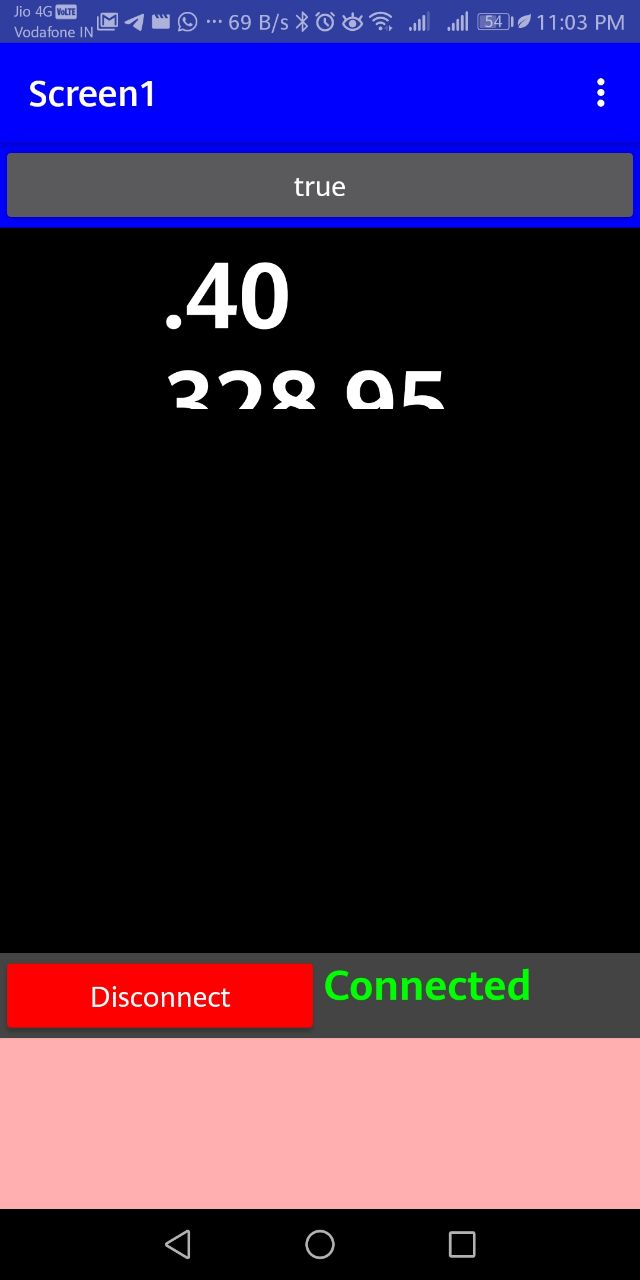
After that I selected the BT address from the app and then connected the board
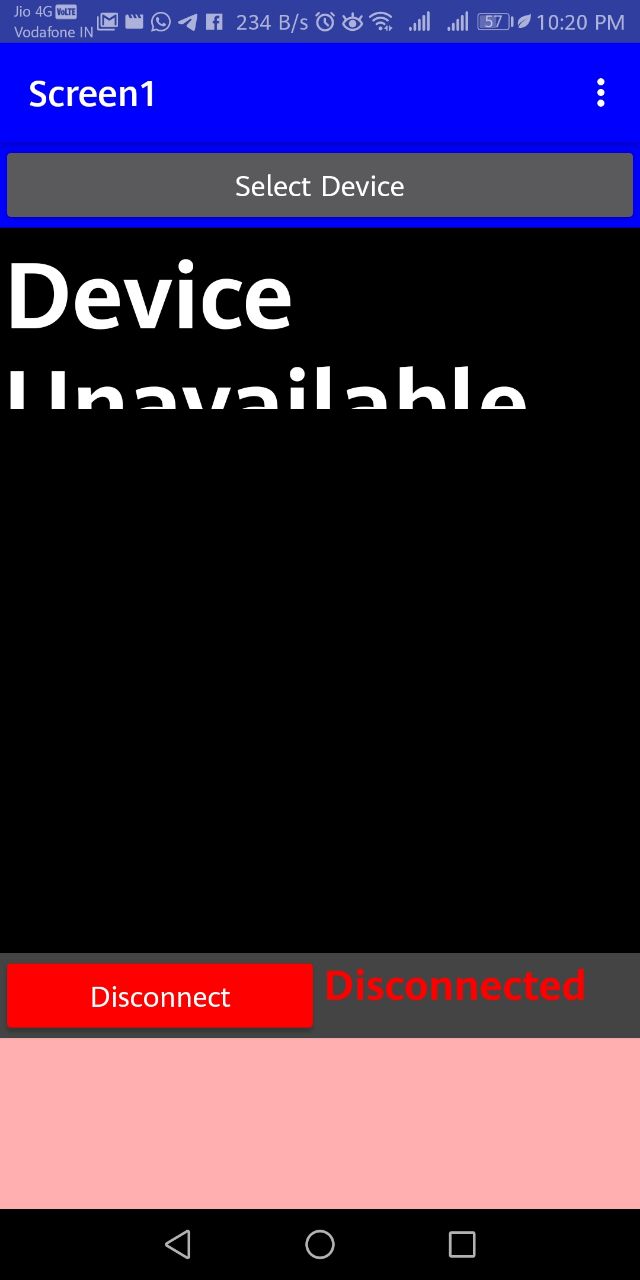
Finally the app showed the degree in desired space which I have allocated during the designing.
With this I have completed the Interface and application week assignment.