Week 9. Embedded Programming
9. Embedded programming
Assignment
Group assignment: “Compare the performance and development workflows for other architectures”
Individual assignment: “Read a microcontroller data sheet.”
Individual assignment: “Program your board to do something, with as many different programming languages and programming environments as possible.”
Files
Arduino file ButtonToLED.ino
Arduino file SensorInputToLED.ino
Arduino file SensorInputToLEDSoftwareSerial.ino
Arduino file SensorInputToLEDSoftwareSerialButton.ino
Arduino file PinChangeInterrupt_Led.ino
PlatformIO project
Datasheet of the ATTiny44
Software
Arduino IDE (Simple IDE to program especially Arduino based microcontrollers)
PlatformIO (terminal based programming environment to program microcontrollers)
ATOM (IDE that can be used with PlatformIO to program microcontrollers)
AVRDude (the AVR programming application used and integrated in the Arduino IDE and PlatformIO)
Hardware
Our Fabacademy ATTiny44 based board made in week07
Our USBtiny made in week 05
A USB to TTL controller. (also know as a FTDI controller)
Group assignment
For your group assignment we compared the performance and development workflows from different architectures. We chose to look at:
- Makey Makey (Micky and Joey)
- ESP8266 chip (Like NodeMCU and WeMos) (Micky and Joey)
- Raspberry Pi Zero (Anne and Heidi)
- 555 chip (Rutger)
We made an excel sheet describing the different aspects of the architectures.
When comparing the architectures we see that we have a diverse combination of devices.
The 555 is really simple and only has a few functions. I do not even consider this a microcontroller, it does not have a form of memory, it only uses external connections for triggers and settings as a threshold.
Next is the Makey Makey with the PIC chip. This is a diverse microcontroller with build in full USB support.
The ESP8266 does not have this USB support as I understand, but does has a good Wifi support, which does not require as much power as we normally expect with wifi.
The Raspberry Pi Zero is a full computer, the ARM chip is a microprocessor and much more powerfull than the microcontrollers. Further it has support for the full Wifi stack and Bluetooth 4. But as with all microprocessors it needs an Operating System to run, and comes with its own Linux build. It runs Python, C and all kind of other languages as with any other computer, making it very powerfull, but also possible to use to program a microcontroller.
Together with Micky, I looked at the Makey Makey and the ESP8266 chip.
The Makey Makey has a PIC microcontroller, making the board pretty powerfull and simple in usage. The full integration of USB support inclusive the ability to be a HID device is very powerfull, and makes me also consider to use this chip for a project once, like for a custom keyboard. But the most impressive feature of the Makey Makey is that you can use it to attach the ports to any product and use is as a button.
The ESP8266 has a lot of onboard memory, 4 megabytes, making it possible to run a small webserver on the chip. It does not support USB, but has two serial ports. Unfortunately it only supports 2.4GHz, not the newer 5GHz spectrum for wifi.
The ATTiny44A Datasheet
When we explore the ATTiny44 datasheet we see much is specified in this 229 pages document. Datasheet of the ATTiny44 We will discuss aspects that are relevant for our usage and most of the times relevant whe using a (unknown) chip:
- basics as operating voltage, memory and (clock)speed
- footprint
- pin layout and features
Basics as Operating voltage, memory and (clock)speed
At our first page we can allready read most basic features and decide what we want to learn more: – 2K/4K Bytes of In-System, Self-Programmable Flash Program Memory – 128/256 Bytes of In-System Programmable EEPROM – 128/256 Bytes of Internal SRAM
- One 8-Bit and One 16-Bit Timer/Counter with Two PWM Channels
- Programmable Watchdog Timer with Separate On-chip Oscillator
- Pin Change Interrupt on 12 Pins
- Twelve Programmable I/O Lines
- Operating Voltage: – 1.8 – 5.5V
- Speed Grade: 0–4 MHz @ 1.8–5.5V
- Speed Grade: 0–10 MHz @ 2.7–5.5V
- Speed Grade: 0–20 MHz @ 4.5–5.5V
- Industrial Temperature Range: -40°C to +85°C – Power consumption Active Mode: 210 μA at 1.8V and 1MHz – Power consumption Idle Mode: 33 μA at 1.8V and 1MHz – Power consumption Power-Down Mode: 0.1 μA at 1.8V and 25°C
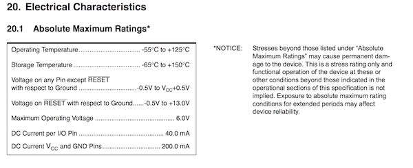
When we want to dive into these characteristics, like voltage minimum and maximum we have to look further. At page 173 we can find the maximum characteristics. Here we see that we can actually put 6V on our chip instead of 5.5V, and on the RESET pin even 13V.
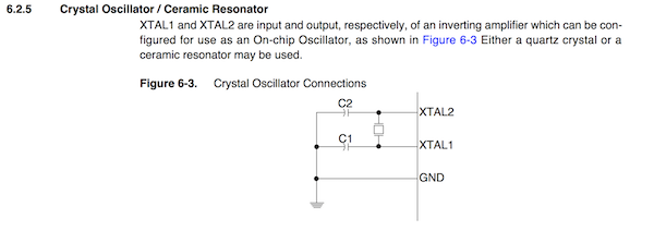
For clocks speed we can actually use different type of clocks. On page 23 we find the different clocks described. For example if we do not want to use the internal clock but an external clock, as we do with our ATTiny board, page 25 describes how to connect and external clock and what kind of external clocks you can use. When chosen an external clock you need to set the CKSEL fuses to 0000.
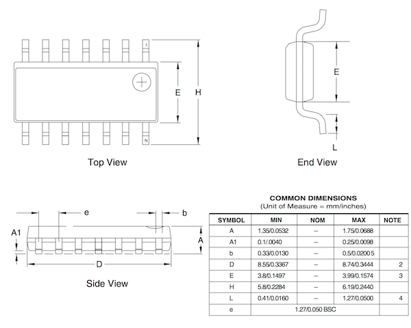
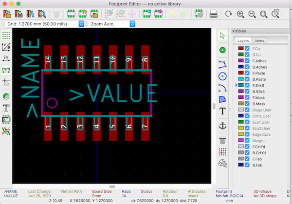
Footprint
On page 220 we find the description of what our chip looks like. This description shows the exact dimensions of the chip. We can use this description in our board design to make a perfect fitting footprint. We actually allready used this footprint design in week 7 when we designed our board in KiCad using the fabacademy footprint library.
 v
v
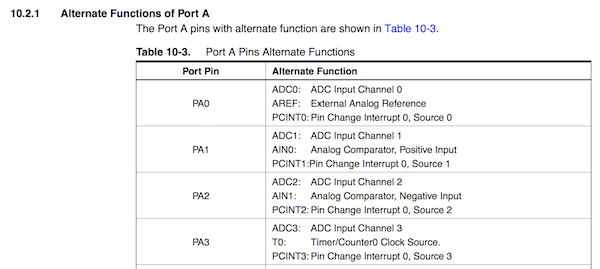
Pin Layout and features
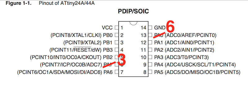
To know what our chip can do and how we can use it by connecting the pins we have to look at the pin layout and description. This is spread over the whole datasheet. A quick overview starts at page 2.
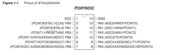
But the actual functions that are abreviated next to the pins are explained at page 59 and further. Here we see the functions explained in full text.
Here we see that almost all pins can be used as input and output pins and even used as interrupt pin. As we will discuss in the interrupt code with our button all interrupt pins are connected to pin 0 which is the actual interrupt pin.
More interesting features are communication pins: MISO pin 5 and MOSI pin 6, that we use to program our ATTiny using our USBTiny.
Programming the board with different programming languages
In this exercise we will be exploring how we can program our ATTiny board using the Arduino IDE and the PlatfromIO IDE. At each section we will explain their advantages and show the workings with blinking a LED.
Arduino environment
A long time ago (2003) in a land far far away (Italy) there was a group that said programming microcontrollers should be more easier. They created the Arduino platform, a combination of a design for a easy to tinker with and program microcontroller developing board and a easy to use development environment. The microcontroller uses an Atmel AVR chip and the development environment is build on the GUI of the Processing development environment, but optimised to use for programming microcontrollers in C. (More details about the history of the Arduino platfor see the Wiki) We will be using our own developed board, not an Arduino, but our board has an Atmel AVR chip (ATTiny44A) and with the correct settings can be programmed using the Arduino environment.
To start download the Arduino Development Environment at https://www.arduino.cc/en/Main/Software
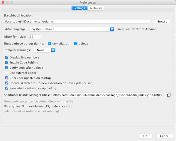
After installing launch the IDE and go to File->Settings and modify the setting to the following properties. You can ignore the “aditional board manager” option for now.
Now the boardmanager. Our Arduino environment does not know about our ATTiny44 chip, we first need to teel the environment about our chip.
We can do this by installing a board manager for the ATTiny.
You can find our ATTiny board manager JSON file at the Arduino playground website https://playground.arduino.cc/Main/ArduinoOnOtherAtmelChips.Copy and paste the ATTiny board manager URL to the file in the “additional board manager” field.

Next we are going to install the board manager for the ATTiny44.
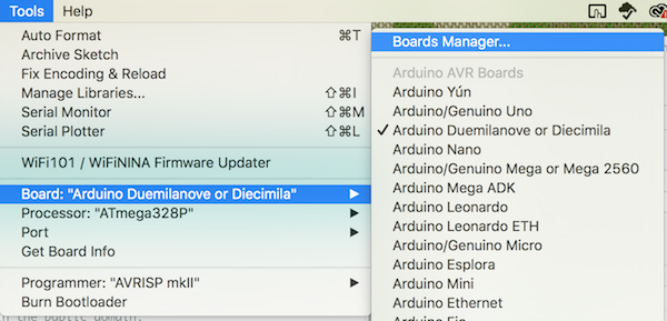
Go to Tools -> Board: -> Board Manager…
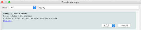
Enter ATTiny in the search field and install the ATTiny board manager.
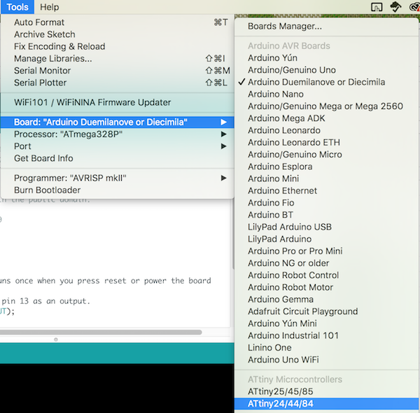
Now we have installed our board manager we can select our ATTiny board in the IDE.
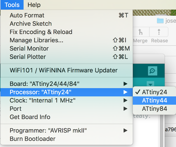
In tools select:
- Board: “ATtiny 24/44/48”
- Processor: “ATTiny 44”
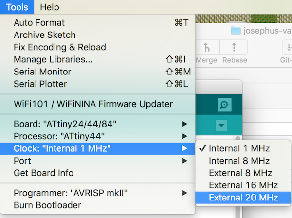
- Clock: “External 20 Mhz”
Setting the fuses on our ATTiny board
Our ATTiny board is still brand new, without any code on it.
Also the chip does not know it can use our resonater to run at 20MHz.
For this we need to set the correct fuses. (burn the fuses)
In the Arduino environment this called burning the bootlader. (while technically for an ATTiny it is not burning a bootloader, but only setting some fuses)
After setting the fuses to our desired uption, we need to make sure that we keep these settings in our Arduino environment when uploading our code. If we use different settings, for example a different clock speed, we will end of having timing issues, which makes Serial communication very difficult, and probably strange blinking LEDs.
To set the fuseson the ATTiny, connect your board using the USBTiny to the computer.

Next make sure you selected your board in the Arduino environment as decribed previously.
- Board: “ATtiny 24/44/48”
- Processor: “ATTiny 44”
- Clock: “External 20 Mhz”
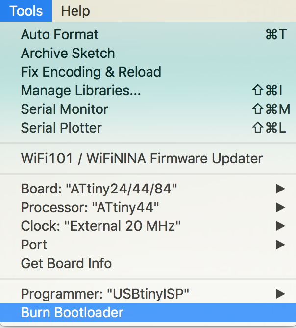
Next select the “USBTinyISP” in the programmer option and select burn bootloader.
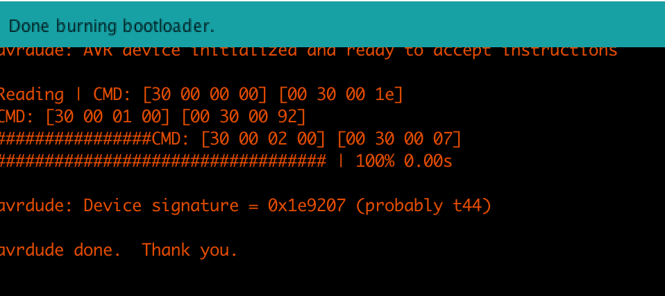
If everything goes well you will see output like this.
/Applications/Arduino.app/Contents/Java/hardware/tools/avr/bin/avrdude -C/Applications/Arduino.app/Contents/Java/hardware/tools/avr/etc/avrdude.conf -v -v -v -v -pattiny44 -cusbtiny -e -Uefuse:w:0xff:m -Uhfuse:w:0xdf:m -Ulfuse:w:0xfe:m

avrdude: Version 6.3-20171130
         Copyright (c) 2000-2005 Brian Dean, http://www.bdmicro.com/
         Copyright (c) 2007-2014 Joerg Wunsch

         System wide configuration file is "/Applications/Arduino.app/Contents/Java/hardware/tools/avr/etc/avrdude.conf"
         User configuration file is "/Users/biejh/.avrduderc"
         User configuration file does not exist or is not a regular file, skipping

         Using Port                    : usb
         Using Programmer              : usbtiny
avrdude: usbdev_open(): Found USBtinyISP, bus:device: 020:018
         AVR Part                      : ATtiny44
         Chip Erase delay              : 4500 us
         PAGEL                         : P00
         BS2                           : P00
         RESET disposition             : possible i/o
         RETRY pulse                   : SCK
         serial program mode           : yes
         parallel program mode         : yes
         Timeout                       : 200
         StabDelay                     : 100
         CmdexeDelay                   : 25
         SyncLoops                     : 32
         ByteDelay                     : 0
         PollIndex                     : 3
         PollValue                     : 0x53
         Memory Detail                 :

                                  Block Poll               Page                       Polled
           Memory Type Mode Delay Size  Indx Paged  Size   Size #Pages MinW  MaxW   ReadBack
           ----------- ---- ----- ----- ---- ------ ------ ---- ------ ----- ----- ---------
           eeprom        65     6     4    0 no        256    4      0  4000  4500 0xff 0xff
                                  Block Poll               Page                       Polled
           Memory Type Mode Delay Size  Indx Paged  Size   Size #Pages MinW  MaxW   ReadBack
           ----------- ---- ----- ----- ---- ------ ------ ---- ------ ----- ----- ---------
           flash         65     6    32    0 yes      4096   64     64  4500  4500 0xff 0xff
                                  Block Poll               Page                       Polled
           Memory Type Mode Delay Size  Indx Paged  Size   Size #Pages MinW  MaxW   ReadBack
           ----------- ---- ----- ----- ---- ------ ------ ---- ------ ----- ----- ---------
           signature      0     0     0    0 no          3    0      0     0     0 0x00 0x00
                                  Block Poll               Page                       Polled
           Memory Type Mode Delay Size  Indx Paged  Size   Size #Pages MinW  MaxW   ReadBack
           ----------- ---- ----- ----- ---- ------ ------ ---- ------ ----- ----- ---------
           lock           0     0     0    0 no          1    0      0  9000  9000 0x00 0x00
                                  Block Poll               Page                       Polled
           Memory Type Mode Delay Size  Indx Paged  Size   Size #Pages MinW  MaxW   ReadBack
           ----------- ---- ----- ----- ---- ------ ------ ---- ------ ----- ----- ---------
           lfuse          0     0     0    0 no          1    0      0  9000  9000 0x00 0x00
                                  Block Poll               Page                       Polled
           Memory Type Mode Delay Size  Indx Paged  Size   Size #Pages MinW  MaxW   ReadBack
           ----------- ---- ----- ----- ---- ------ ------ ---- ------ ----- ----- ---------
           hfuse          0     0     0    0 no          1    0      0  9000  9000 0x00 0x00
                                  Block Poll               Page                       Polled
           Memory Type Mode Delay Size  Indx Paged  Size   Size #Pages MinW  MaxW   ReadBack
           ----------- ---- ----- ----- ---- ------ ------ ---- ------ ----- ----- ---------
           efuse          0     0     0    0 no          1    0      0  9000  9000 0x00 0x00
                                  Block Poll               Page                       Polled
           Memory Type Mode Delay Size  Indx Paged  Size   Size #Pages MinW  MaxW   ReadBack
           ----------- ---- ----- ----- ---- ------ ------ ---- ------ ----- ----- ---------
           calibration    0     0     0    0 no          1    0      0     0     0 0x00 0x00

         Programmer Type : USBtiny
         Description     : USBtiny simple USB programmer, https://learn.adafruit.com/usbtinyisp
avrdude: programmer operation not supported

avrdude: Using SCK period of 10 usec
CMD: [ac 53 00 00] [ff fe 53 00]
avrdude: AVR device initialized and ready to accept instructions

/Applications/Arduino.app/Contents/Java/hardware/tools/avr/bin/avrdude -C/Applications/Arduino.app/Contents/Java/hardware/tools/avr/etc/avrdude.conf -v -v -v -v -pattiny44 -cusbtiny

avrdude: Version 6.3-20171130
         Copyright (c) 2000-2005 Brian Dean, http://www.bdmicro.com/
         Copyright (c) 2007-2014 Joerg Wunsch

         System wide configuration file is "/Applications/Arduino.app/Contents/Java/hardware/tools/avr/etc/avrdude.conf"
Reading | CMD: [30 00 00 00] [00 30 00 1e]
CMD: [30 00 01 00] [00 30 00 92]
################CMD: [30 00 02 00] [00 30 00 07]
################################## | 100% 0.00s

avrdude: Device signature = 0x1e9207 (probably t44)
avrdude: erasing chip
CMD: [ac 80 00 00] [00 ac 80 00]
avrdude: Using SCK period of 10 usec
CMD: [ac 53 00 00] [00 ac 53 00]
avrdude: reading input file "0xff"
avrdude: writing efuse (1 bytes):

Writing | CMD: [50 08 00 00] [00 50 08 ff]
################################################## | 100% 0.00s

avrdude: 1 bytes of efuse written
avrdude: verifying efuse memory against 0xff:
avrdude: load data efuse data from input file 0xff:
avrdude: input file 0xff contains 1 bytes
avrdude: reading on-chip efuse data:

Reading | CMD: [50 08 00 00] [00 50 08 ff]
################################################## | 100% 0.00s

avrdude: verifying ...
avrdude: 1 bytes of efuse verified
avrdude: reading input file "0xdf"
avrdude: writing hfuse (1 bytes):

Writing | CMD: [58 08 00 00] [00 58 08 df]
################################################## | 100% 0.00s

avrdude: 1 bytes of hfuse written
avrdude: verifying hfuse memory against 0xdf:
avrdude: load data hfuse data from input file 0xdf:
avrdude: input file 0xdf contains 1 bytes
avrdude: reading on-chip hfuse data:

Reading | CMD: [58 08 00 00] [00 58 08 df]
################################################## | 100% 0.00s

avrdude: verifying ...
avrdude: 1 bytes of hfuse verified
avrdude: reading input file "0xfe"
avrdude: writing lfuse (1 bytes):

Writing | CMD: [50 00 00 00] [00 50 00 fe]
################################################## | 100% 0.00s

avrdude: 1 bytes of lfuse written
avrdude: verifying lfuse memory against 0xfe:
avrdude: load data lfuse data from input file 0xfe:
avrdude: input file 0xfe contains 1 bytes
avrdude: reading on-chip lfuse data:

Reading | CMD: [50 00 00 00] [00 50 00 fe]
################################################## | 100% 0.00s

avrdude: verifying ...
avrdude: 1 bytes of lfuse verified

avrdude done.  Thank you.

         User configuration file is "/Users/biejh/.avrduderc"
         User configuration file does not exist or is not a regular file, skipping

         Using Port                    : usb
         Using Programmer              : usbtiny
avrdude: usbdev_open(): Found USBtinyISP, bus:device: 020:018
         AVR Part                      : ATtiny44
         Chip Erase delay              : 4500 us
         PAGEL                         : P00
         BS2                           : P00
         RESET disposition             : possible i/o
         RETRY pulse                   : SCK
         serial program mode           : yes
         parallel program mode         : yes
         Timeout                       : 200
         StabDelay                     : 100
         CmdexeDelay                   : 25
         SyncLoops                     : 32
         ByteDelay                     : 0
         PollIndex                     : 3
         PollValue                     : 0x53
         Memory Detail                 :

                                  Block Poll               Page                       Polled
           Memory Type Mode Delay Size  Indx Paged  Size   Size #Pages MinW  MaxW   ReadBack
           ----------- ---- ----- ----- ---- ------ ------ ---- ------ ----- ----- ---------
           eeprom        65     6     4    0 no        256    4      0  4000  4500 0xff 0xff
                                  Block Poll               Page                       Polled
           Memory Type Mode Delay Size  Indx Paged  Size   Size #Pages MinW  MaxW   ReadBack
           ----------- ---- ----- ----- ---- ------ ------ ---- ------ ----- ----- ---------
           flash         65     6    32    0 yes      4096   64     64  4500  4500 0xff 0xff
                                  Block Poll               Page                       Polled
           Memory Type Mode Delay Size  Indx Paged  Size   Size #Pages MinW  MaxW   ReadBack
           ----------- ---- ----- ----- ---- ------ ------ ---- ------ ----- ----- ---------
           signature      0     0     0    0 no          3    0      0     0     0 0x00 0x00
                                  Block Poll               Page                       Polled
           Memory Type Mode Delay Size  Indx Paged  Size   Size #Pages MinW  MaxW   ReadBack
           ----------- ---- ----- ----- ---- ------ ------ ---- ------ ----- ----- ---------
           lock           0     0     0    0 no          1    0      0  9000  9000 0x00 0x00
                                  Block Poll               Page                       Polled
           Memory Type Mode Delay Size  Indx Paged  Size   Size #Pages MinW  MaxW   ReadBack
           ----------- ---- ----- ----- ---- ------ ------ ---- ------ ----- ----- ---------
           lfuse          0     0     0    0 no          1    0      0  9000  9000 0x00 0x00
                                  Block Poll               Page                       Polled
           Memory Type Mode Delay Size  Indx Paged  Size   Size #Pages MinW  MaxW   ReadBack
           ----------- ---- ----- ----- ---- ------ ------ ---- ------ ----- ----- ---------
           hfuse          0     0     0    0 no          1    0      0  9000  9000 0x00 0x00
                                  Block Poll               Page                       Polled
           Memory Type Mode Delay Size  Indx Paged  Size   Size #Pages MinW  MaxW   ReadBack
           ----------- ---- ----- ----- ---- ------ ------ ---- ------ ----- ----- ---------
           efuse          0     0     0    0 no          1    0      0  9000  9000 0x00 0x00
                                  Block Poll               Page                       Polled
           Memory Type Mode Delay Size  Indx Paged  Size   Size #Pages MinW  MaxW   ReadBack
           ----------- ---- ----- ----- ---- ------ ------ ---- ------ ----- ----- ---------
           calibration    0     0     0    0 no          1    0      0     0     0 0x00 0x00

         Programmer Type : USBtiny
         Description     : USBtiny simple USB programmer, https://learn.adafruit.com/usbtinyisp
avrdude: programmer operation not supported

avrdude: Using SCK period of 10 usec
CMD: [ac 53 00 00] [00 00 53 00]
avrdude: AVR device initialized and ready to accept instructions

Reading | CMD: [30 00 00 00] [00 30 00 1e]
CMD: [30 00 01 00] [00 30 00 92]
################CMD: [30 00 02 00] [00 30 00 07]
################################## | 100% 0.00s

avrdude: Device signature = 0x1e9207 (probably t44)

avrdude done.  Thank you.
Next we will upload a programm to our board, continue to the Blinking our LED
Blinking our LED
We are going to let our LED on our board blink by creating and upload a small sketch.
Create a new sketch: File->New
And put in the following code:
/*
  Blink for our FabAcademy ATTiny
  http://fab.academany.org/2019/labs/waag/students/josephus-vanderbie//week07.html
  Turns on an LED on for one second, then off for one second, repeatedly.
  This code is modified from the regular Arduino blink example.

  This example code is in the public domain.

  modified 12 March 2019
  by Joey van der Bie
 */

const int LED_PIN = 7;

// the setup function runs once when you press reset or power the board
void setup() {
  // initialize digital pin 13 as an output.
  pinMode(LED_PIN, OUTPUT);
}

// the loop function runs over and over again forever
void loop() {
  digitalWrite(LED_PIN, HIGH);   // turn the LED on (HIGH is the voltage level)
  delay(1000);              // wait for a second
  digitalWrite(LED_PIN, LOW);    // turn the LED off by making the voltage LOW
  delay(1000);              // wait for a second
}
Programming the Phototransistor
In this exercise we will create a program that can read the phototransistor value and blinks the LED based on the transistor value.
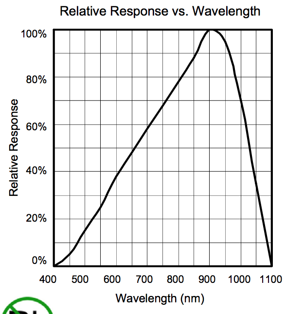
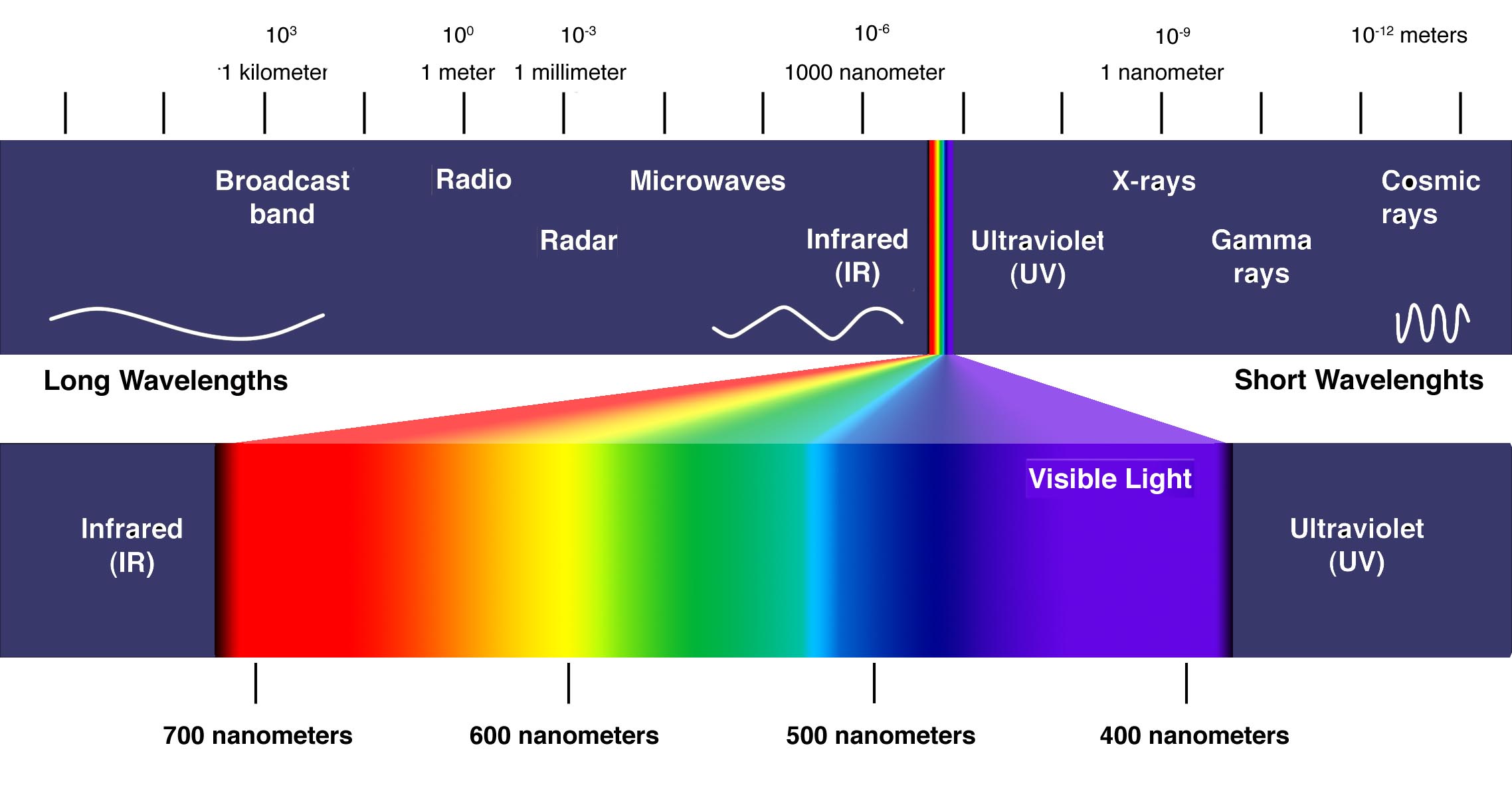
An phototransistor is a transistor that is influenced by light. By reading the output value of the phototransistor in our microcontroller we can get an indication how much light shines on our sensor. In the datasheet of our transistor we see the properties and that our transistor is highly sensitive for 900 nm wavelenghts.
The transistor gives a analog signal, and this is best measured using one of the analog inputs of the ATTiny.
Measuring analog values in the ATTiny has a min value of 0 and a maximum of 1023 for the range of 0V to 5V.
Having a range of 1023 means we can directly map the input value to a delay for our LED, a delay of 1000ms for on and of is not that long.
In our design we connected the transistor to our Analog Input pin 2 and the LED to pin 7 giving the following code:
/*
  Analog Input to LED

  Demonstrates analog input by reading an analog sensor (PHOTOTRANSISTOR) on analog pin 0 and
  turning on and off a light emitting diode(LED) connected to digital pin 7.
  The amount of time the LED will be on and off depends on the value obtained
  by analogRead().
  This code is optimised for usage with the ATTiny44A

  created by David Cuartielles
  modified 30 Aug 2011
  By Tom Igoe
  modified 12 Mar 2019
  by Joey van der Bie

  This example code is in the public domain.

  http://www.arduino.cc/en/Tutorial/AnalogInput
*/

const int PHOTOTRANSISTOR_PIN = A2;    // select the input pin for the PHOTOTRANSISTOR
const int LED_PIN = 7;     // select the pin for the LED
int sensorValue = 0;  // variable to store the value coming from the sensor

void setup() {
  // declare the LED pin as an OUTPUT:
  pinMode(LED_PIN, OUTPUT);
}

void loop() {
  // read the value from the sensor:
  sensorValue = analogRead(PHOTOTRANSISTOR_PIN);
  // turn the ledPin on
  digitalWrite(LED_PIN, HIGH);
  // stop the program for <sensorValue> milliseconds:
  delay(sensorValue);
  // turn the ledPin off:
  digitalWrite(LED_PIN, LOW);
  // stop the program for for <sensorValue> milliseconds:
  delay(sensorValue);
}
Software Serial
In the phototransistor example you might have noticed the LED blinking to not fully represent the 0ms till 1023 ms delay it could have based on our analog port resolution. To understand how much the range is of our transistor we need to see the actual measurements. We can do this by sending the measurements from our microcontroller to our computer. We will do this using a serial interface over USB.
So far we have been communicating with our ATTiny using the USBTiny and the ISP interface. A lot of hardware applications and Arduino examples use a different form of communication, serial. Unfortunately our ATTiny44 does not support Serial communication out of the box, but we can add this feature in our applications using the Software Serial library.
/*
  Analog Input to LED and to Serial

  Demonstrates analog input by reading an analog sensor (PHOTOTRANSISTOR) on analog pin 0,
  sending its value over Software Serial and
  turning on and off a light emitting diode(LED) connected to digital pin 7.
  The amount of time the LED will be on and off depends on the value obtained
  by analogRead().
  This code is optimised for usage with the ATTiny44A

  created by David Cuartielles
  modified 30 Aug 2011
  By Tom Igoe
  modified 12 Mar 2019
  by Joey van der Bie

  This example code is in the public domain.

  http://www.arduino.cc/en/Tutorial/AnalogInput
*/
#include <SoftwareSerial.h>
#define RX    1
#define TX    0

const int PHOTOTRANSISTOR_PIN = A2;    // select the input pin for the PHOTOTRANSISTOR
const int LED_PIN = 7;     // select the pin for the LED
int sensorValue = 0;  // variable to store the value coming from the sensor

SoftwareSerial Serial(RX, TX);

void setup() {
  //Start serial
  Serial.begin(9600);
  Serial.println("Initializing...");

  // declare the LED pin as an OUTPUT:
  pinMode(LED_PIN, OUTPUT);
  // declare the PHOTOTRANSISTOR pin as an INPUT
  pinMode(PHOTOTRANSISTOR_PIN, INPUT);
}

void loop() {
  // read the value from the sensor:
  sensorValue = analogRead(PHOTOTRANSISTOR_PIN);

  // map the value to a broader range to compensate for small difference in the PHOTOTRANSISTOR
//  sensorValue = map(sensorValue, 900, 1023, 0, 1023);

  //Send the value over the Serial line to the computer
  Serial.println(sensorValue);

  // turn the ledPin on
  digitalWrite(LED_PIN, HIGH);
  // stop the program for <sensorValue> milliseconds:
  delay(sensorValue);
  // turn the ledPin off:
  digitalWrite(LED_PIN, LOW);
  // stop the program for for <sensorValue> milliseconds:
  delay(sensorValue);
}
Still we have code, but as mentioned by your Arduino environment our ATTiny is not connected to our computer using a serial interface for this follow the next steps.

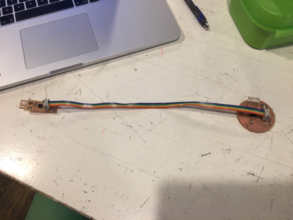
Connecting the ATTiny board to computer using the USB to TTL converter
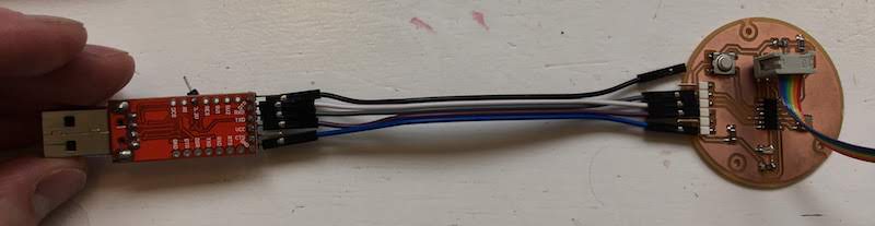
When we want our ATTiny board to communicate with our computer using the USB port we need to use a device that adds a USB port at our board.
For this we can use a USB to TTL converter, this small board usses a FTDI chip to convert the USB to serial for your ATTiny.
Before we connect anything first make sure you have the drivers for the FTDI chip on your computers.
Windows computers have the drivers by default, for Mac computers you can find the software here https://www.silabs.com/products/development-tools/software/usb-to-uart-bridge-vcp-drivers#mac
Next connect your dive to the converter using jumper wires in the following combination:
| USB to TTL converter | ATTiny board |
|---|---|
| VCC | VCC |
| GND | GND |
| TXD | RX |
| RXD | TX |
Be carefull with the next steps. If you still have your USBTiny connected to your ATTiny board and your USBTiny still has the soldered bridge, remove the USBTiny first. When you have an desoldered bridge on your USBTiny you do not have to disconnect your board. Why do you need to do this with the soldered bridge? Well, the bridge provides power to your ATTiny board via the USBTiny, and in our next step the USB to TTL converter will also supply power to your ATTiny board. So you might by accident provide your ATTiny board with 2 times 5 volt (2 x 5 = 10 volt) instead of just 5 volt. Not all your components might properly support 10 volt and this might damage your ATTiny board or even your computer.
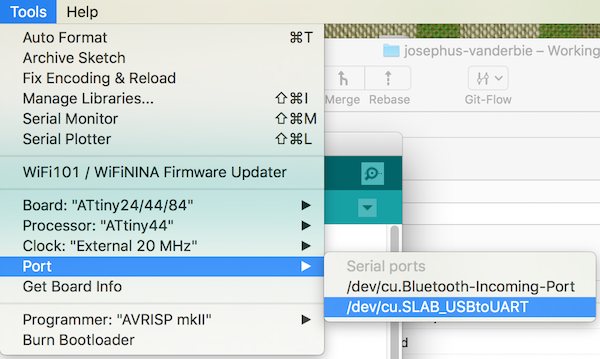
Now check if your computer detects the converter, by inserting the converter in your USB port and selecting it in the Arduino environment in the Tools-> Port -> “/dev/cu.SLAB_USBtoUART”
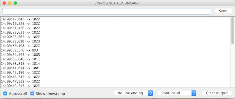
If you successfully uploaded the example code of the Software Serial you will see a blinkin LED on your converter. This means the ATTiny is sending data over the serial line. Open the Serial Monitor in the Arduino environment to see its output, this are the values we measure from our analog input port connected to our transistor.
Calibrating a sensor
If you play with the amount of light on your phototransistor you will see the values change in the Serial monitor.
You might also notice you do not see the full range of your anolog resolutions (0 - 1023), but more something like 400 - 800.
This is because your transistor does not work over the full 0V to 5V spectrum and the light conditions presented do not fully utilize the full potential of the transistor. That is ok, to make life easier for us we can calibrate our system. Meaning we will adjust our system to work with the minimum and maximum values that our transistor can provide given the current situation.
To convert the values we do get from our transistor to for example represent the full 0-1023 range, Arduino has a special function included called map().
With map we can convert a number within a certain range to a number within a different range. More details at the reference guide of Arduino..
The map function works as follows:
map ( the measured value, measured minimum, measured maximum, desired minimum, desired maximum );
In the provided code of the example you see the map function allready provided, you only need to edit the new minumum and maximum values.
Determine the minimum value by fully covering your phototransistor and then looking at its value.
Determine the maximum value by shining a bright light directly at your phototransistor and taking that measured value.
Uncomment the map code, give it the minimum and maximum values determined and look at the new sensor values shown in the terminal.
If you now play with light on the transistor you will see the values in the terminal much more represent the full range of 0-1023.
Detecting a button press
We have attached a button to our board at pin 3 of our ATTiny.
We can write a small script that can detect this button press.
Only we need to be carefull, the button passes through the VCC to input pin 3.
You should not directly connect your VCC to the input, but always put a resistor in between to avoid a shortcut. If we check the datasheet of our button, we see this resistor is not present in our button, it simply is a switch with two legs on each side, and an extra ground leg.
Also when the button is not pressed nothing is connected tot he input pin, leaving a floating pin.
When you checked the Attiny44 datasheet on page 58 you see “All port pins have individually selectable pull-up resistors”, meaning we can activate a pull up resistor for pin 3 via software.
Upload the following code to your ATTiny to light a LED when the button is pressed.
/*
  Button

  Turns on and off a light emitting diode(LED),
  when pressing a pushbutton attached with internal pull up register.
  Code optimised for the ATTiny44

  The circuit:
  - LED attached from pin 7 to ground
  - pushbutton attached to pin 3 from VCC

  created 2005
  by DojoDave <http://www.0j0.org>
  modified 30 Aug 2011
  by Tom Igoe
  modified 12 March 2019
  by Joey van der Bie

  This example code is in the public domain.

  http://www.arduino.cc/en/Tutorial/Button
*/

// constants won't change. They're used here to set pin numbers:
const int BUTTON_PIN = 3;     // the number of the pushbutton pin
const int LED_PIN =  7;      // the number of the LED pin

// variables will change:
int buttonState = 0;         // variable for reading the pushbutton status

void setup() {
  // initialize the LED pin as an output:
  pinMode(LED_PIN, OUTPUT);
  //configure pin 3 as an input and enable the internal pull-up resistor
  pinMode(BUTTON_PIN, INPUT_PULLUP);
}

void loop() {
  // read the state of the pushbutton value:
  buttonState = digitalRead(BUTTON_PIN);

  // check if the pushbutton is pressed. If it is, the buttonState is HIGH:
  if (buttonState == LOW) {
    // turn LED on:
    digitalWrite(LED_PIN, HIGH);
  } else {
    // turn LED off:
    digitalWrite(LED_PIN, LOW);
  }
}
While this code works, when you extend your code and input more logic, you might notice you will miss button presses. To avoid this we can use a special feature, called the interrupt.
The interrupt feature allows us to look if the input value of a pin has changed. We can look if the pin is LOW, HIGH, RISING, FALLING and CHANGED.
Unfortunately the ATTiny only pin 0 really supports this feature, the other I/O puns can be used as interrupt, but do this via pin 0.
This is called a pin change interrupt.
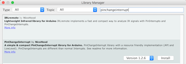
The pin change interrupt for the ATTiny is not directly supported by the Arduino environment, we first need to install the PinChangeInterrupt library from the library manager.
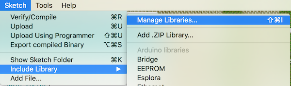
Go to Sketch->Include library->Manage libraries…
And install the PinChangeInterrupt library.
Go to Sketch->Include library->Manage libraries…
And install the PinChangeInterrupt library.
We implement the button press using the pin interrupt with the following code.
/*
  Copyright (c) 2014-2015 NicoHood
  See the readme for credit to other people.

  Modified for ATTiny Fabacademy design
  Modified 13 March 2019
  By Joey van der Bie
*/

#include "PinChangeInterrupt.h"

// Choose a valid PinChangeInterrupt pin of your Arduino board
#define BUTTON_PIN 3
#define LED_PIN 7

void setup() {
  // set pin to input with a pullup, led to output
  pinMode(BUTTON_PIN, INPUT_PULLUP);
  pinMode(LED_PIN, OUTPUT);

  // Manually blink once to test if LED is functional
  blinkLed();
  delay(1000);
  blinkLed();

  // Attach the new PinChangeInterrupt and enable event function below
  attachPCINT(digitalPinToPCINT(BUTTON_PIN), blinkLed, CHANGE);
}

void blinkLed(void) {
  // Switch Led state
  digitalWrite(LED_PIN, !digitalRead(LED_PIN));
}

void loop() {
  // Nothing to do here
}
Unfortunately this interrupt cannot be used directly with the Software Serial, due to both libraries using pin 0 for the interrupt. A different ATTiny firmware should allow for a combination of serial and pin change interrupt. This firmware has a special version of SoftwareSerial, that does not use the PinChange interrupt, but the Analog interrupts of pin 0 and 1. This has the downside that you cannot send and receive at the same time, but the upside that you can keep using the pinchange interrupts.
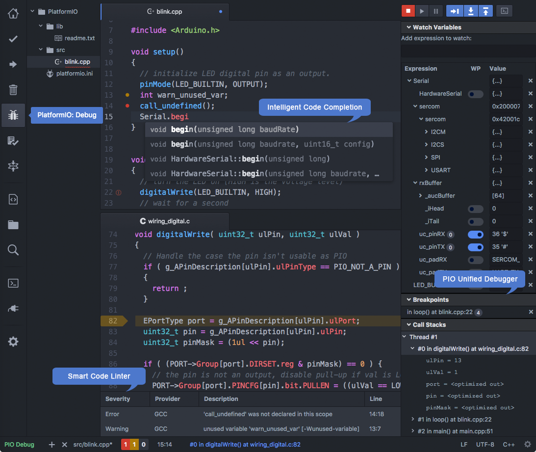
Platform IO
Next to using the Arduino IDE, we will also try to install our ATTiny using PlatformIO. The advantage of PlatformIO compared to Arduino IDE is that you can use both an IDE as terminal command. This makes debugging in theory easier and allows for more advance programming of your board.
For example you can set special build flags in the terminal or in a configuration file, making your work also transferable to other computers and users. Last there are many libraries for PlatformIO, and it is especially populair for chips as the ESP8266.
You can find PlatformIO at https://platformio.org/
The PlatformIO team made it easy to integrate their program with different IDE’s, we will be exploring the platform with Atom.

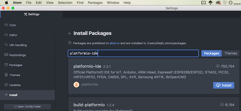
First we will install the ATOM IDE from https://atom.io/
Next we install PlatformIO via the package manager in ATOM,
Go to File -> Settings. Then select “Install” and search for the “platformio-IDE”.
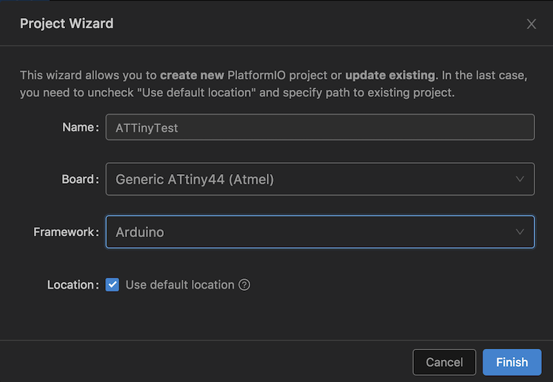
Next create a new project and select:
- board: “Generic ATTiny44”
- platform: “Arduino”
Next open the main.cpp in the src folder and write the following code to create a new blink sketch:
#include <Arduino.h>

const int LED_PIN = 3;

// the setup function runs once when you press reset or power the board
void setup() {
  // initialize digital pin 3 as an output.
  pinMode(LED_PIN, OUTPUT);
}

// the loop function runs over and over again forever
void loop() {
  digitalWrite(LED_PIN, HIGH);   // turn the LED on (HIGH is the voltage level)
  delay(1000);              // wait for a second
  digitalWrite(LED_PIN, LOW);    // turn the LED off by making the voltage LOW
  delay(1000);              // wait for a second
}
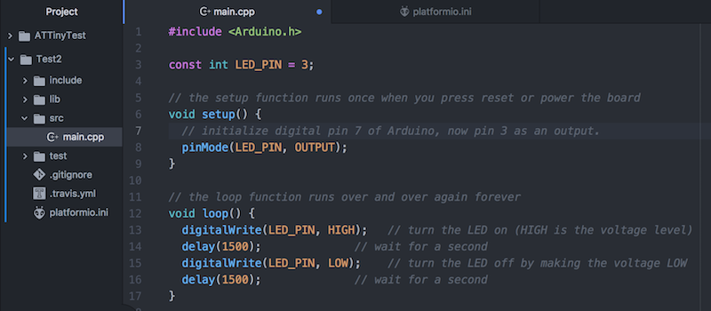
As you can see in the code our pin-layout is different from the Arduino, and does not match the datasheet.
What normally would be pin 7 is now pin 3 and what normally is pin 0 is now pin 6.
New pin layouts as in PlatformIO
Next we need to configure the platform to upload the code to the ATTiny. We are using a programmer, so we need to edit the configuration to fit the programmer.
Open the platformio.ini file and enter the following settings:
[env:attiny44]
platform = atmelavr
board = attiny44
framework = arduino
; change MCU frequency
board_build.f_cpu = 20000000L
upload_protocol = usbtiny
Most settings are self explaining:
- platform is atmelavr, because our ATTiny44 is part of this architecture
- board is our ATTiny44 chip
- framework is Arduino
- board_build.f_cpu is 20000000L because this is the external clock speed
- the upload protocol is our usbtiny
Last we we can build and upload our code.
Open the terminal and put there the command:
platformio run -v -t program
Your output will look something like this:
Processing attiny44 (upload_protocol: usbtiny; platform: atmelavr; board_build.f_cpu: 20000000L; board: attiny44; framework: arduino)
------------------------------------------------------------------------------------------------------------------------------------------------

CONFIGURATION: https://docs.platformio.org/page/boards/atmelavr/attiny44.html
PLATFORM: Atmel AVR > Generic ATtiny44
HARDWARE: ATTINY44 20MHz 256B RAM (4KB Flash)
Library Dependency Finder -> http://bit.ly/configure-pio-ldf
LDF MODES: FINDER(chain) COMPATIBILITY(soft)

Collected 6 compatible libraries
Scanning dependencies...
No dependencies
avr-g++ -o .pioenvs/attiny44/src/main.cpp.o -c -fno-exceptions -fno-threadsafe-statics -fpermissive -std=gnu++11 -Os -Wall -ffunction-sections -
fdata-sections -flto -mmcu=attiny44 -DPLATFORMIO=30605 -DARDUINO_AVR_ATTINYX4 -DF_CPU=20000000L -DARDUINO_ARCH_AVR -DARDUINO=10805 -Isrc -Iinclu
de -I/Users/biejh/.platformio/packages/framework-arduinoavr/cores/tiny -I/Users/biejh/.platformio/packages/framework-arduinoavr/variants/tinyX4
src/main.cpp
avr-gcc-ar rc .pioenvs/attiny44/libFrameworkArduinoVariant.a
avr-gcc-ranlib .pioenvs/attiny44/libFrameworkArduinoVariant.a
avr-g++ -o .pioenvs/attiny44/FrameworkArduino/HardwareSerial.cpp.o -c -fno-exceptions -fno-threadsafe-statics -fpermissive -std=gnu++11 -Os -Wal
l -ffunction-sections -fdata-sections -flto -mmcu=attiny44 -DPLATFORMIO=30605 -DARDUINO_AVR_ATTINYX4 -DF_CPU=20000000L -DARDUINO_ARCH_AVR -DARDU
INO=10805 -I/Users/biejh/.platformio/packages/framework-arduinoavr/cores/tiny -I/Users/biejh/.platformio/packages/framework-arduinoavr/variants/
tinyX4 /Users/biejh/.platformio/packages/framework-arduinoavr/cores/tiny/HardwareSerial.cpp
avr-g++ -o .pioenvs/attiny44/FrameworkArduino/Print.cpp.o -c -fno-exceptions -fno-threadsafe-statics -fpermissive -std=gnu++11 -Os -Wall -ffunct
ion-sections -fdata-sections -flto -mmcu=attiny44 -DPLATFORMIO=30605 -DARDUINO_AVR_ATTINYX4 -DF_CPU=20000000L -DARDUINO_ARCH_AVR -DARDUINO=10805

 -I/Users/biejh/.platformio/packages/framework-arduinoavr/cores/tiny -I/Users/biejh/.platformio/packages/framework-arduinoavr/variants/tinyX4 /U
sers/biejh/.platformio/packages/framework-arduinoavr/cores/tiny/Print.cpp
avr-g++ -o .pioenvs/attiny44/FrameworkArduino/Stream.cpp.o -c -fno-exceptions -fno-threadsafe-statics -fpermissive -std=gnu++11 -Os -Wall -ffunc
tion-sections -fdata-sections -flto -mmcu=attiny44 -DPLATFORMIO=30605 -DARDUINO_AVR_ATTINYX4 -DF_CPU=20000000L -DARDUINO_ARCH_AVR -DARDUINO=1080
5 -I/Users/biejh/.platformio/packages/framework-arduinoavr/cores/tiny -I/Users/biejh/.platformio/packages/framework-arduinoavr/variants/tinyX4 /
Users/biejh/.platformio/packages/framework-arduinoavr/cores/tiny/Stream.cpp
avr-g++ -o .pioenvs/attiny44/FrameworkArduino/TinySoftwareSerial.cpp.o -c -fno-exceptions -fno-threadsafe-statics -fpermissive -std=gnu++11 -Os
-Wall -ffunction-sections -fdata-sections -flto -mmcu=attiny44 -DPLATFORMIO=30605 -DARDUINO_AVR_ATTINYX4 -DF_CPU=20000000L -DARDUINO_ARCH_AVR -D
ARDUINO=10805 -I/Users/biejh/.platformio/packages/framework-arduinoavr/cores/tiny -I/Users/biejh/.platformio/packages/framework-arduinoavr/varia
nts/tinyX4 /Users/biejh/.platformio/packages/framework-arduinoavr/cores/tiny/TinySoftwareSerial.cpp
avr-g++ -o .pioenvs/attiny44/FrameworkArduino/Tone.cpp.o -c -fno-exceptions -fno-threadsafe-statics -fpermissive -std=gnu++11 -Os -Wall -ffuncti
on-sections -fdata-sections -flto -mmcu=attiny44 -DPLATFORMIO=30605 -DARDUINO_AVR_ATTINYX4 -DF_CPU=20000000L -DARDUINO_ARCH_AVR -DARDUINO=10805
-I/Users/biejh/.platformio/packages/framework-arduinoavr/cores/tiny -I/Users/biejh/.platformio/packages/framework-arduinoavr/variants/tinyX4 /Us
ers/biejh/.platformio/packages/framework-arduinoavr/cores/tiny/Tone.cpp
avr-gcc -o .pioenvs/attiny44/FrameworkArduino/WInterrupts.c.o -c -std=gnu11 -fno-fat-lto-objects -Os -Wall -ffunction-sections -fdata-sections -
flto -mmcu=attiny44 -DPLATFORMIO=30605 -DARDUINO_AVR_ATTINYX4 -DF_CPU=20000000L -DARDUINO_ARCH_AVR -DARDUINO=10805 -I/Users/biejh/.platformio/pa
ckages/framework-arduinoavr/cores/tiny -I/Users/biejh/.platformio/packages/framework-arduinoavr/variants/tinyX4 /Users/biejh/.platformio/package
s/framework-arduinoavr/cores/tiny/WInterrupts.c
avr-g++ -o .pioenvs/attiny44/FrameworkArduino/WMath.cpp.o -c -fno-exceptions -fno-threadsafe-statics -fpermissive -std=gnu++11 -Os -Wall -ffunct
ion-sections -fdata-sections -flto -mmcu=attiny44 -DPLATFORMIO=30605 -DARDUINO_AVR_ATTINYX4 -DF_CPU=20000000L -DARDUINO_ARCH_AVR -DARDUINO=10805
 -I/Users/biejh/.platformio/packages/framework-arduinoavr/cores/tiny -I/Users/biejh/.platformio/packages/framework-arduinoavr/variants/tinyX4 /U
sers/biejh/.platformio/packages/framework-arduinoavr/cores/tiny/WMath.cpp
avr-g++ -o .pioenvs/attiny44/FrameworkArduino/abi.cpp.o -c -fno-exceptions -fno-threadsafe-statics -fpermissive -std=gnu++11 -Os -Wall -ffunctio
n-sections -fdata-sections -flto -mmcu=attiny44 -DPLATFORMIO=30605 -DARDUINO_AVR_ATTINYX4 -DF_CPU=20000000L -DARDUINO_ARCH_AVR -DARDUINO=10805 -
I/Users/biejh/.platformio/packages/framework-arduinoavr/cores/tiny -I/Users/biejh/.platformio/packages/framework-arduinoavr/variants/tinyX4 /Use
rs/biejh/.platformio/packages/framework-arduinoavr/cores/tiny/abi.cpp
avr-g++ -o .pioenvs/attiny44/FrameworkArduino/main.cpp.o -c -fno-exceptions -fno-threadsafe-statics -fpermissive -std=gnu++11 -Os -Wall -ffuncti
on-sections -fdata-sections -flto -mmcu=attiny44 -DPLATFORMIO=30605 -DARDUINO_AVR_ATTINYX4 -DF_CPU=20000000L -DARDUINO_ARCH_AVR -DARDUINO=10805
-I/Users/biejh/.platformio/packages/framework-arduinoavr/cores/tiny -I/Users/biejh/.platformio/packages/framework-arduinoavr/variants/tinyX4 /Us
ers/biejh/.platformio/packages/framework-arduinoavr/cores/tiny/main.cpp
avr-g++ -o .pioenvs/attiny44/FrameworkArduino/new.cpp.o -c -fno-exceptions -fno-threadsafe-statics -fpermissive -std=gnu++11 -Os -Wall -ffunctio
n-sections -fdata-sections -flto -mmcu=attiny44 -DPLATFORMIO=30605 -DARDUINO_AVR_ATTINYX4 -DF_CPU=20000000L -DARDUINO_ARCH_AVR -DARDUINO=10805 -
I/Users/biejh/.platformio/packages/framework-arduinoavr/cores/tiny -I/Users/biejh/.platformio/packages/framework-arduinoavr/variants/tinyX4 /Use
rs/biejh/.platformio/packages/framework-arduinoavr/cores/tiny/new.cpp
avr-gcc -o .pioenvs/attiny44/FrameworkArduino/wiring.c.o -c -std=gnu11 -fno-fat-lto-objects -Os -Wall -ffunction-sections -fdata-sections -flto
-mmcu=attiny44 -DPLATFORMIO=30605 -DARDUINO_AVR_ATTINYX4 -DF_CPU=20000000L -DARDUINO_ARCH_AVR -DARDUINO=10805 -I/Users/biejh/.platformio/package
s/framework-arduinoavr/cores/tiny -I/Users/biejh/.platformio/packages/framework-arduinoavr/variants/tinyX4 /Users/biejh/.platformio/packages/fra

mework-arduinoavr/cores/tiny/wiring.c
avr-gcc -o .pioenvs/attiny44/FrameworkArduino/wiring_analog.c.o -c -std=gnu11 -fno-fat-lto-objects -Os -Wall -ffunction-sections -fdata-sections
 -flto -mmcu=attiny44 -DPLATFORMIO=30605 -DARDUINO_AVR_ATTINYX4 -DF_CPU=20000000L -DARDUINO_ARCH_AVR -DARDUINO=10805 -I/Users/biejh/.platformio/
packages/framework-arduinoavr/cores/tiny -I/Users/biejh/.platformio/packages/framework-arduinoavr/variants/tinyX4 /Users/biejh/.platformio/packa
ges/framework-arduinoavr/cores/tiny/wiring_analog.c
avr-gcc -o .pioenvs/attiny44/FrameworkArduino/wiring_digital.c.o -c -std=gnu11 -fno-fat-lto-objects -Os -Wall -ffunction-sections -fdata-section
s -flto -mmcu=attiny44 -DPLATFORMIO=30605 -DARDUINO_AVR_ATTINYX4 -DF_CPU=20000000L -DARDUINO_ARCH_AVR -DARDUINO=10805 -I/Users/biejh/.platformio
/packages/framework-arduinoavr/cores/tiny -I/Users/biejh/.platformio/packages/framework-arduinoavr/variants/tinyX4 /Users/biejh/.platformio/pack
ages/framework-arduinoavr/cores/tiny/wiring_digital.c
avr-gcc -o .pioenvs/attiny44/FrameworkArduino/wiring_pulse.c.o -c -std=gnu11 -fno-fat-lto-objects -Os -Wall -ffunction-sections -fdata-sections
-flto -mmcu=attiny44 -DPLATFORMIO=30605 -DARDUINO_AVR_ATTINYX4 -DF_CPU=20000000L -DARDUINO_ARCH_AVR -DARDUINO=10805 -I/Users/biejh/.platformio/p
ackages/framework-arduinoavr/cores/tiny -I/Users/biejh/.platformio/packages/framework-arduinoavr/variants/tinyX4 /Users/biejh/.platformio/packag
es/framework-arduinoavr/cores/tiny/wiring_pulse.c
avr-gcc -o .pioenvs/attiny44/FrameworkArduino/wiring_shift.c.o -c -std=gnu11 -fno-fat-lto-objects -Os -Wall -ffunction-sections -fdata-sections
-flto -mmcu=attiny44 -DPLATFORMIO=30605 -DARDUINO_AVR_ATTINYX4 -DF_CPU=20000000L -DARDUINO_ARCH_AVR -DARDUINO=10805 -I/Users/biejh/.platformio/p
ackages/framework-arduinoavr/cores/tiny -I/Users/biejh/.platformio/packages/framework-arduinoavr/variants/tinyX4 /Users/biejh/.platformio/packag
es/framework-arduinoavr/cores/tiny/wiring_shift.c
avr-gcc-ar rc .pioenvs/attiny44/libFrameworkArduino.a .pioenvs/attiny44/FrameworkArduino/HardwareSerial.cpp.o .pioenvs/attiny44/FrameworkArduino
/Print.cpp.o .pioenvs/attiny44/FrameworkArduino/Stream.cpp.o .pioenvs/attiny44/FrameworkArduino/TinySoftwareSerial.cpp.o .pioenvs/attiny44/Frame
workArduino/Tone.cpp.o .pioenvs/attiny44/FrameworkArduino/WInterrupts.c.o .pioenvs/attiny44/FrameworkArduino/WMath.cpp.o .pioenvs/attiny44/Frame
workArduino/WString.cpp.o .pioenvs/attiny44/FrameworkArduino/abi.cpp.o .pioenvs/attiny44/FrameworkArduino/main.cpp.o .pioenvs/attiny44/Framework
Arduino/new.cpp.o .pioenvs/attiny44/FrameworkArduino/wiring.c.o .pioenvs/attiny44/FrameworkArduino/wiring_analog.c.o .pioenvs/attiny44/Framework
Arduino/wiring_digital.c.o .pioenvs/attiny44/FrameworkArduino/wiring_pulse.c.o .pioenvs/attiny44/FrameworkArduino/wiring_shift.c.o
avr-gcc-ranlib .pioenvs/attiny44/libFrameworkArduino.a
avr-g++ -o .pioenvs/attiny44/firmware.elf -Os -mmcu=attiny44 -Wl,--gc-sections -flto -fuse-linker-plugin .pioenvs/attiny44/src/main.cpp.o -L.pio
envs/attiny44 -Wl,--start-group .pioenvs/attiny44/libFrameworkArduinoVariant.a .pioenvs/attiny44/libFrameworkArduino.a -lm -Wl,--end-group
MethodWrapper(["checkprogsize"], [".pioenvs/attiny44/firmware.elf"])
avr-objcopy -O ihex -R .eeprom .pioenvs/attiny44/firmware.elf .pioenvs/attiny44/firmware.hex
Memory Usage -> http://bit.ly/pio-memory-usage
DATA:    [          ]   3.5% (used 9 bytes from 256 bytes)
PROGRAM: [==        ]  19.0% (used 780 bytes from 4096 bytes)
.pioenvs/attiny44/firmware.elf  :
section                    size      addr
.text                       780         0
.data                         0   8388704
.bss                          9   8388704
.comment                     17         0

.note.gnu.avr.deviceinfo     60         0
.debug_aranges               64         0
.debug_info                1406         0
.debug_abbrev              1040         0
.debug_line                 258         0
.debug_str                  371         0
Total                      4005
<lambda>(["program"], [".pioenvs/attiny44/firmware.hex"])
AVAILABLE: usbtiny
CURRENT: upload_protocol = usbtiny
BeforeUpload(["program"], [".pioenvs/attiny44/firmware.hex"])
avrdude -v -p attiny44 -C /Users/biejh/.platformio/packages/tool-avrdude/avrdude.conf -c usbtiny -U flash:w:.pioenvs/attiny44/firmware.hex:i

avrdude: Version 6.3, compiled on Jan 17 2017 at 12:01:35
Copyright (c) 2000-2005 Brian Dean, http://www.bdmicro.com/
Copyright (c) 2007-2014 Joerg Wunsch

System wide configuration file is "/Users/biejh/.platformio/packages/tool-avrdude/avrdude.conf"
User configuration file is "/Users/biejh/.avrduderc"
User configuration file does not exist or is not a regular file, skipping

Using Port                    : usb
Using Programmer              : usbtiny
avrdude: usbdev_open(): Found USBtinyISP, bus:device: 020:016
AVR Part                      : ATtiny44
Chip Erase delay              : 4500 us
PAGEL                         : P00
BS2                           : P00
RESET disposition             : possible i/o
RETRY pulse                   : SCK
serial program mode           : yes
parallel program mode         : yes
Timeout                       : 200
StabDelay                     : 100
CmdexeDelay                   : 25
SyncLoops                     : 32

ByteDelay                     : 0
PollIndex                     : 3
PollValue                     : 0x53
Memory Detail                 :

Block Poll               Page                       Polled
Memory Type Mode Delay Size  Indx Paged  Size   Size #Pages MinW  MaxW   ReadBack
----------- ---- ----- ----- ---- ------ ------ ---- ------ ----- ----- ---------
eeprom        65     6     4    0 no        256    4      0  4000  4500 0xff 0xff
flash         65     6    32    0 yes      4096   64     64  4500  4500 0xff 0xff
signature      0     0     0    0 no          3    0      0     0     0 0x00 0x00
lock           0     0     0    0 no          1    0      0  9000  9000 0x00 0x00
lfuse          0     0     0    0 no          1    0      0  9000  9000 0x00 0x00
hfuse          0     0     0    0 no          1    0      0  9000  9000 0x00 0x00
efuse          0     0     0    0 no          1    0      0  9000  9000 0x00 0x00
calibration    0     0     0    0 no          1    0      0     0     0 0x00 0x00

Programmer Type : USBtiny
Description     : USBtiny simple USB programmer, http://www.ladyada.net/make/usbtinyisp/
avrdude: programmer operation not supported

avrdude: Using SCK period of 10 usec
avrdude: AVR device initialized and ready to accept instructions

Reading | ################################################## | 100% 0.00s

avrdude: Device signature = 0x1e9207 (probably t44)
avrdude: safemode: hfuse reads as DF
avrdude: safemode: efuse reads as FF
avrdude: NOTE: "flash" memory has been specified, an erase cycle will be performed
To disable this feature, specify the -D option.
avrdude: erasing chip
avrdude: Using SCK period of 10 usec
avrdude: reading input file ".pioenvs/attiny44/firmware.hex"

avrdude: writing flash (780 bytes):

Writing | ################################################## | 100% 1.01s

avrdude: 780 bytes of flash written
avrdude: verifying flash memory against .pioenvs/attiny44/firmware.hex:
avrdude: load data flash data from input file .pioenvs/attiny44/firmware.hex:
avrdude: input file .pioenvs/attiny44/firmware.hex contains 780 bytes
avrdude: reading on-chip flash data:

Reading | ################################################## | 100% 1.33s

avrdude: verifying ...
avrdude: 780 bytes of flash verified

avrdude: safemode: hfuse reads as DF
avrdude: safemode: efuse reads as FF
avrdude: safemode: Fuses OK (E:FF, H:DF, L:FE)

avrdude done.  Thank you.

========================================================= [SUCCESS] Took 3.38 seconds =========================================================
Fail
No serial connection
I ould not get the serial connection with my ATtiny and computer to work. To debug I tried in the following order:
- Switch the RX and TX wires (no succes)
- A different computer (no succes)
- A diferent USB to TTL converter (no succes)
- Different wires with the same USB to TTL converter (succes!) One of my wires was broken.
No Software Serial and interrupt
I tried to attach a Pin interrupt to my button using the example form the PinChange interrupt library.
This worked as a charm, however when combining with my Software Serial code, I got a compiler error.
After some reading in the source code of both libraries and in the Arduino help fora, I had to conclude both libraries use the PinChange interrupts which apparently conflitcs. I read the the ATTiny44 datasheet and unfortunately there is only one PinChange interrupt refence, pin 0.
On that same forum topic I found a different ATTiny firmware that should allow for a combination of serial and pinchange interrupt.
This firmware has a special version of SoftwareSerial, that does not use the PinChange interrupt, but the Analog interrupts of pin 0 and 1. This has the downside that you cannot send and receive at the same time, but the upside that you can keep using the pinchange interrupts.
If in the future I only need to send data over serial instead of send and receive, I can also use the SendOnlySoftwareSerial library.
Phototransistor sensitive for IR light

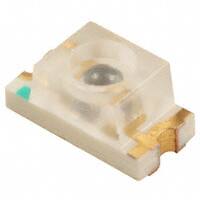
When trying to get the Phototransistor to work, I noticed there was a very small difference (100 difference) in maximum light (flashlight directly on the sensor) and minimum light ( sensor covered with finger).
When looking at the partslist of the fabacademy, I came to the conclusion I should have soldered the phototransistor 1080-1380-1-ND , while I have installed the phototransistor 365-1157-1-ND.
When analyzing the datasheet of the 365-1157-1-nd, we see this is only sensistive for the 900nm wavelength, meaning infrared light. Unfortunatelty we only have IR sensitive phototransistors at the moment, so I wont be replacing it for now.
PlatformIO does not flash on ATTiny?
Unfortunately the PlatformIO installer did not worked out of the box. After selecting the USBTiny as the programmer and performing the installation via:
pio run -t program
The code was not installed on the ATTiny, but on the USBTiny!
When trying to debug, I checked if the installation still worked via the Arduino IDE, this was the case.
I tried to compare if there was a difference in AVRdude settings, and I could not find any differences. To check this, I copied the Arduino AVRdude command and replaced it with the file compiled by PlatformIO. This still installed the blink on the USBTiny instead of the ATTiny, letting me to conclude the problem is in de compilation of the file, not in the AVRdude command and my problem is somewhere else.
Bellow is given the two different AVRdude results.
The Arduino blink sketch:
C02KR0SBFFRP:~ biejh$ /Applications/Arduino.app/Contents/Java/hardware/tools/avr/bin/avrdude -C/Applications/Arduino.app/Contents/Java/hardware/tools/avr/etc/avrdude.conf -v -pattiny44 -cusbtiny -Uflash:w:/var/folders/cf/kkh_r72x0jq1wqb573gs9w980000gs/T/arduino_build_543962/Blink.ino.hex:i

avrdude: Version 6.3-20171130
         Copyright (c) 2000-2005 Brian Dean, http://www.bdmicro.com/
         Copyright (c) 2007-2014 Joerg Wunsch

         System wide configuration file is "/Applications/Arduino.app/Contents/Java/hardware/tools/avr/etc/avrdude.conf"
         User configuration file is "/Users/biejh/.avrduderc"
         User configuration file does not exist or is not a regular file, skipping

         Using Port                    : usb
         Using Programmer              : usbtiny
avrdude: usbdev_open(): Found USBtinyISP, bus:device: 020:011
         AVR Part                      : ATtiny44
         Chip Erase delay              : 4500 us
         PAGEL                         : P00
         BS2                           : P00
         RESET disposition             : possible i/o
         RETRY pulse                   : SCK
         serial program mode           : yes
         parallel program mode         : yes
         Timeout                       : 200
         StabDelay                     : 100
         CmdexeDelay                   : 25
         SyncLoops                     : 32
         ByteDelay                     : 0
         PollIndex                     : 3
         PollValue                     : 0x53
         Memory Detail                 :

                                  Block Poll               Page                       Polled
           Memory Type Mode Delay Size  Indx Paged  Size   Size #Pages MinW  MaxW   ReadBack
           ----------- ---- ----- ----- ---- ------ ------ ---- ------ ----- ----- ---------
           eeprom        65     6     4    0 no        256    4      0  4000  4500 0xff 0xff
           flash         65     6    32    0 yes      4096   64     64  4500  4500 0xff 0xff
           signature      0     0     0    0 no          3    0      0     0     0 0x00 0x00
           lock           0     0     0    0 no          1    0      0  9000  9000 0x00 0x00
           lfuse          0     0     0    0 no          1    0      0  9000  9000 0x00 0x00
           hfuse          0     0     0    0 no          1    0      0  9000  9000 0x00 0x00
           efuse          0     0     0    0 no          1    0      0  9000  9000 0x00 0x00
           calibration    0     0     0    0 no          1    0      0     0     0 0x00 0x00

         Programmer Type : USBtiny
         Description     : USBtiny simple USB programmer, https://learn.adafruit.com/usbtinyisp
avrdude: programmer operation not supported

avrdude: Using SCK period of 10 usec
avrdude: AVR device initialized and ready to accept instructions

Reading | ################################################## | 100% 0.00s

avrdude: Device signature = 0x1e9207 (probably t44)
avrdude: safemode: lfuse reads as FE
avrdude: safemode: hfuse reads as DF
avrdude: safemode: efuse reads as FF
avrdude: NOTE: "flash" memory has been specified, an erase cycle will be performed
         To disable this feature, specify the -D option.
avrdude: erasing chip
avrdude: Using SCK period of 10 usec
avrdude: reading input file "/var/folders/cf/kkh_r72x0jq1wqb573gs9w980000gs/T/arduino_build_543962/Blink.ino.hex"
avrdude: writing flash (738 bytes):

Writing | ################################################## | 100% 0.98s

avrdude: 738 bytes of flash written
avrdude: verifying flash memory against /var/folders/cf/kkh_r72x0jq1wqb573gs9w980000gs/T/arduino_build_543962/Blink.ino.hex:
avrdude: load data flash data from input file /var/folders/cf/kkh_r72x0jq1wqb573gs9w980000gs/T/arduino_build_543962/Blink.ino.hex:
avrdude: input file /var/folders/cf/kkh_r72x0jq1wqb573gs9w980000gs/T/arduino_build_543962/Blink.ino.hex contains 738 bytes
avrdude: reading on-chip flash data:

Reading | ################################################## | 100% 1.21s

avrdude: verifying ...
avrdude: 738 bytes of flash verified

avrdude: safemode: lfuse reads as FE
avrdude: safemode: hfuse reads as DF
avrdude: safemode: efuse reads as FF
avrdude: safemode: Fuses OK (E:FF, H:DF, L:FE)

avrdude done.  Thank you.
The PlatfromIO sketch:
/Applications/Arduino.app/Contents/Java/hardware/tools/avr/bin/avrdude -C/Applications/Arduino.app/Contents/Java/hardware/tools/avr/etc/avrdude.conf -v -pattiny44 -cusbtiny -U flash:w:/Users/biejh/Documents/PlatformIO/Projects/ATTinyTest/.pioenvs/myattiny44/firmware.hex:i

avrdude: Version 6.3-20171130
         Copyright (c) 2000-2005 Brian Dean, http://www.bdmicro.com/
         Copyright (c) 2007-2014 Joerg Wunsch

         System wide configuration file is "/Applications/Arduino.app/Contents/Java/hardware/tools/avr/etc/avrdude.conf"
         User configuration file is "/Users/biejh/.avrduderc"
         User configuration file does not exist or is not a regular file, skipping

         Using Port                    : usb
         Using Programmer              : usbtiny
avrdude: usbdev_open(): Found USBtinyISP, bus:device: 020:011
         AVR Part                      : ATtiny44
         Chip Erase delay              : 4500 us
         PAGEL                         : P00
         BS2                           : P00
         RESET disposition             : possible i/o
         RETRY pulse                   : SCK
         serial program mode           : yes
         parallel program mode         : yes
         Timeout                       : 200
         StabDelay                     : 100
         CmdexeDelay                   : 25
         SyncLoops                     : 32
         ByteDelay                     : 0
         PollIndex                     : 3
         PollValue                     : 0x53
         Memory Detail                 :

                                  Block Poll               Page                       Polled
           Memory Type Mode Delay Size  Indx Paged  Size   Size #Pages MinW  MaxW   ReadBack
           ----------- ---- ----- ----- ---- ------ ------ ---- ------ ----- ----- ---------
           eeprom        65     6     4    0 no        256    4      0  4000  4500 0xff 0xff
           flash         65     6    32    0 yes      4096   64     64  4500  4500 0xff 0xff
           signature      0     0     0    0 no          3    0      0     0     0 0x00 0x00
           lock           0     0     0    0 no          1    0      0  9000  9000 0x00 0x00
           lfuse          0     0     0    0 no          1    0      0  9000  9000 0x00 0x00
           hfuse          0     0     0    0 no          1    0      0  9000  9000 0x00 0x00
           efuse          0     0     0    0 no          1    0      0  9000  9000 0x00 0x00
           calibration    0     0     0    0 no          1    0      0     0     0 0x00 0x00

         Programmer Type : USBtiny
         Description     : USBtiny simple USB programmer, https://learn.adafruit.com/usbtinyisp
avrdude: programmer operation not supported

avrdude: Using SCK period of 10 usec
avrdude: AVR device initialized and ready to accept instructions

Reading | ################################################## | 100% 0.00s

avrdude: Device signature = 0x1e9207 (probably t44)
avrdude: safemode: lfuse reads as FE
avrdude: safemode: hfuse reads as DF
avrdude: safemode: efuse reads as FF
avrdude: NOTE: "flash" memory has been specified, an erase cycle will be performed
         To disable this feature, specify the -D option.
avrdude: erasing chip
avrdude: Using SCK period of 10 usec
avrdude: reading input file "/Users/biejh/Documents/PlatformIO/Projects/ATTinyTest/.pioenvs/myattiny44/firmware.hex"
avrdude: writing flash (724 bytes):

Writing | ################################################## | 100% 0.98s

avrdude: 724 bytes of flash written
avrdude: verifying flash memory against /Users/biejh/Documents/PlatformIO/Projects/ATTinyTest/.pioenvs/myattiny44/firmware.hex:
avrdude: load data flash data from input file /Users/biejh/Documents/PlatformIO/Projects/ATTinyTest/.pioenvs/myattiny44/firmware.hex:
avrdude: input file /Users/biejh/Documents/PlatformIO/Projects/ATTinyTest/.pioenvs/myattiny44/firmware.hex contains 724 bytes
avrdude: reading on-chip flash data:

Reading | ################################################## | 100% 1.21s

avrdude: verifying ...
avrdude: 724 bytes of flash verified

avrdude: safemode: lfuse reads as FE
avrdude: safemode: hfuse reads as DF
avrdude: safemode: efuse reads as FF
avrdude: safemode: Fuses OK (E:FF, H:DF, L:FE)

avrdude done.  Thank you.

C02KR0SBFFRP:~ biejh$ /Applications/Arduino.app/Contents/Java/hardware/tools/avr/bin/avrdude -C/AppliC02KR0SBFFRP:~ biejh$ /Applications/Arduino.app/Contents/Java/hardware/tools/avr/bin/avrdude -C/Applications/Arduino.app/Contents/Java/hardware/tools/avr/etc/avrdude.conf -v -pattiny44 -cusbtiny -Uflash:w:/var/folders/cf/kkh_r72x0jq1wqb573gs9w980000gs/T/arduino_build_543962/Blink.ino.hex:i
So I thought the problem was that I programmed my USBTiny instead of my ATTiny board. But this wasn’t the case.
After long thinking and looking at the code, I realized that I had another problem, the pins were not mapped the same way as with the Arduino.
This is offcourse an important clue to my problem. Maybe I had selected the pin that was directly connected to the RX of the USBTiny, and instead of sending data over this line, my ATTiny was trying to blink a LED.
After realizing this, I tried out different pins untill I saw the LED blink on my board.
I had to use pin 3 instead of pin 7.
So the real problem was the pin layout that does not make sense compared to what you read in the datasheet or compared to the Arduino layout.