Fab Academy 2020
Introduction
In computing, an input device is a piece of computer hardware equipment used to provide data and control signals to an information processing system such as a computer or information appliance. Examples of input devices include keyboards, mouse, scanners, digital cameras and joysticks. Input devices are actually sensing the environment or accepting the triggers from the enviorment and sent a signal to the connected microcontroller and provides a desired output.So this week deals with making board which can sent an input to do some desired function.
For my input week i am using a rotary encoder and trying to control the brightness of an led and switching it on/off and study how input devices interact with its enviornment.Different types of input devices
What is a rotary encoder?
A rotary encoder, also called a shaft encoder, is an electro-mechanical device that converts the angular position or motion of a shaft or axle to an analog or digital output signals. There are two main types of rotary encoder: absolute and incremental. The output of an absolute encoder indicates the current shaft position, making it an angle transducer. The output of an incremental encoder provides information about the motion of the shaft, which typically is processed elsewhere into information such as position, speed, and distance.
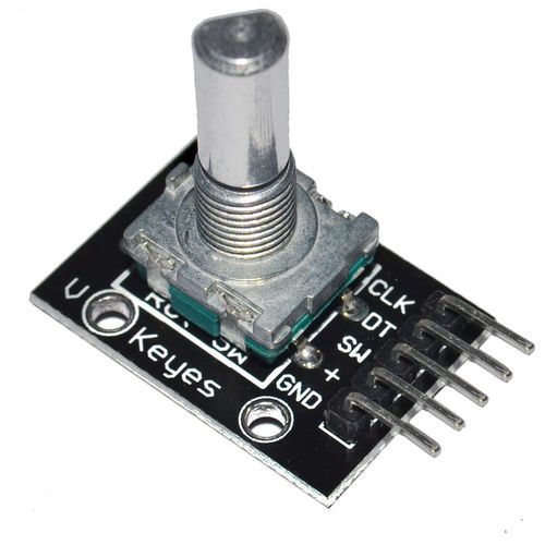
A rotary encoder has a shaft which can be rotated and also used as a switch.
The encoder has a disk with evenly spaced contact zones that are connected to the common pin C and two other separate contact pins A and B, as illustrated below.
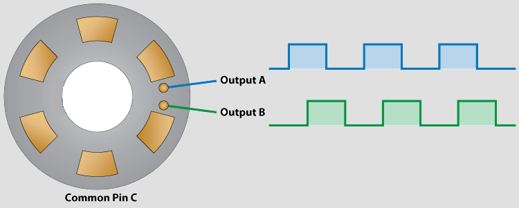
When the disk will start rotating step by step, the pins A and B will start making contact with the common pin and the two square wave output signals will be generated accordingly. Any of the two outputs can be used for determining the rotated position if we just count the pulses of the signal. However, if we want to determine the rotation direction as well, we need to consider both signals at the same time.
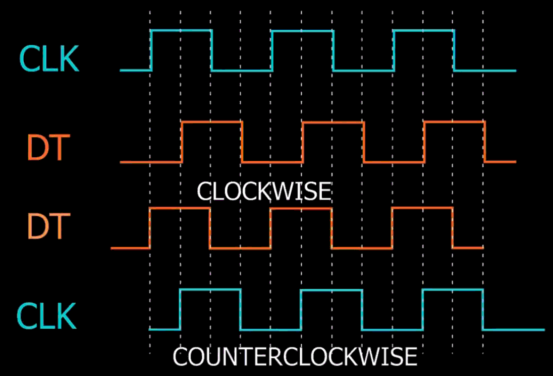
We can notice that the two output signals are displaced at 90 degrees out of phase from each other. If the encoder is rotating clockwise the output A will be ahead of output B. So if we count the steps each time the signal changes, from High to Low or from Low to High, we can notice at that time the two output signals have opposite values. Vice versa, if the encoder is rotating counter-clockwise, the output signals have equal values. So considering this, we can easily program our controller to read the encoder position and the rotation direction.
Group Assignment
The group assignement for this week is explained in detail in the group page. To access the group page click here.
Board designing
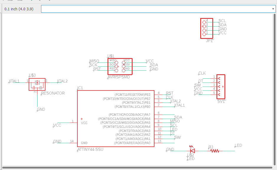
For desgning the board i refered boards from previous years. And had an idea of which componets are necessary. First i arranged the components in the schematic since i didnt use a ftdi pin i added a pinheader to use for I2C communication in the networking week. I am getting used to board desgning and slowly understanding how to make a board design fast.
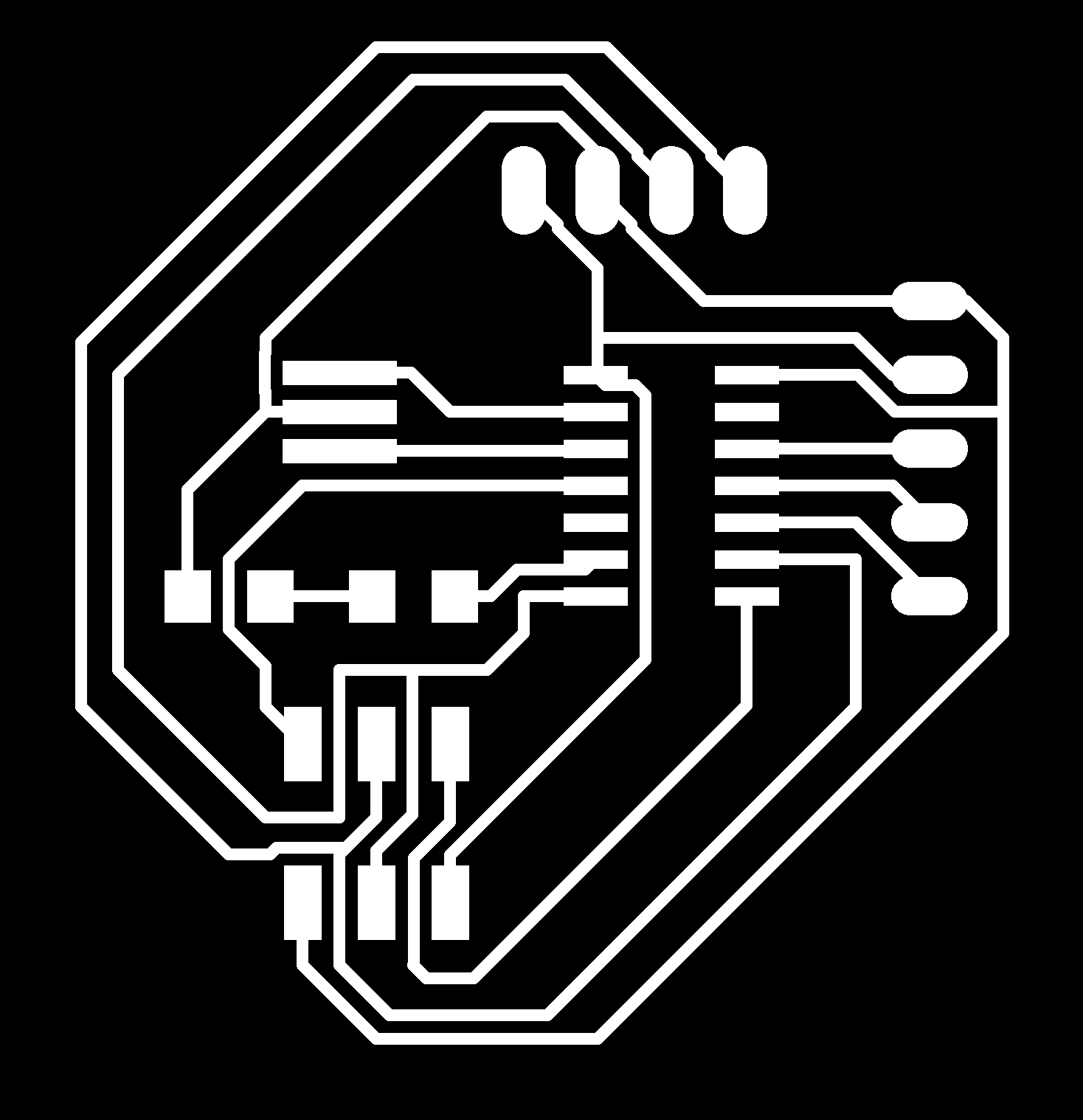
This is the board design after autorouting.
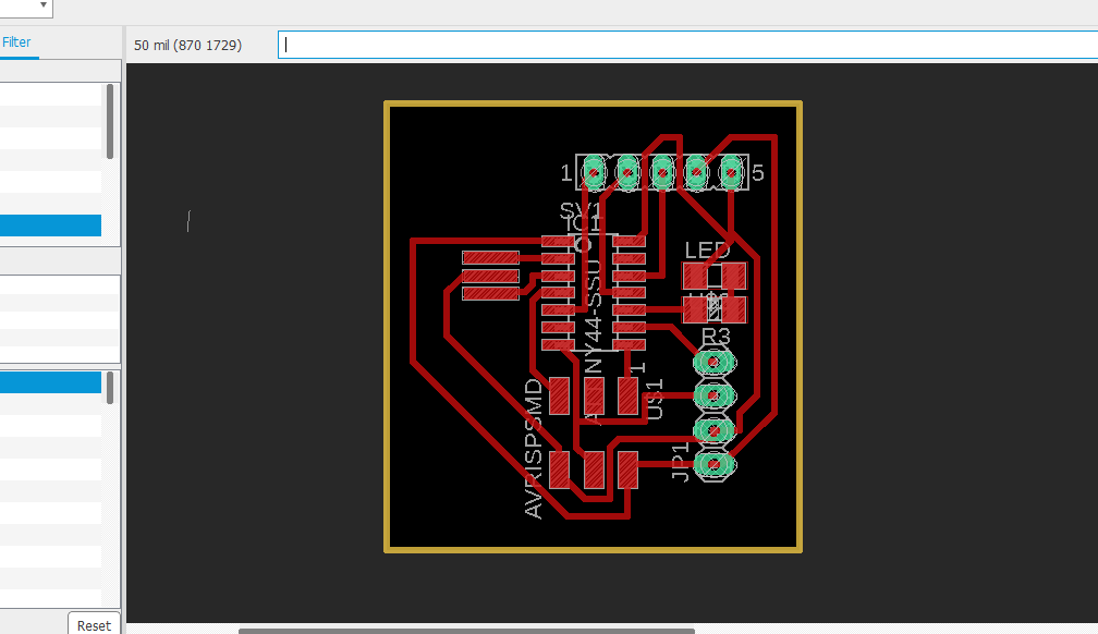
For this design i made a mistake .I realised it after cutiing and soldering the board. its very important to verify the design before soldering. I forget to connect SCL pin to microcontroller so the board didnt pass the initial check and also forgot another circuit.
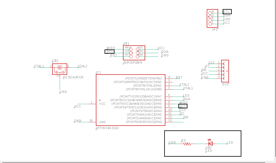
Schematic file after rearranging the components this time i cross checked the board throughly.Additional changes can be is highlighted in the above screenshot.
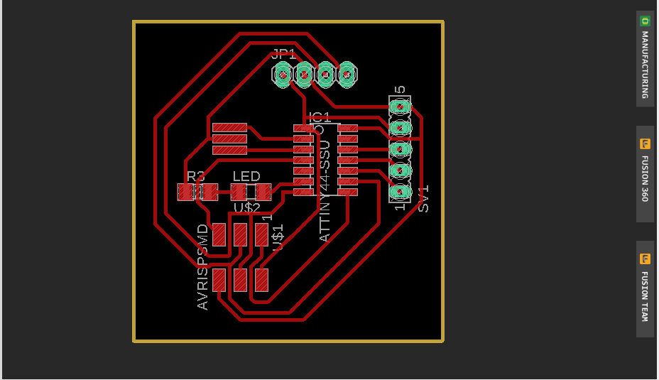
Board file after routing the trace path.
In previous electronic designing week only 2 design files where used for PCB milling. But since we have to drill hole we need to use 3 parts to mill.

All the other details can be found in Electronic designing week.
Board fabrication
Components used.
| Attiny 84 | 1 |
| AVRISP | 1 |
| Red LED | 1 |
| Pinheader male | 4 head |
| Pinheader female | 5 head |
| XTAL resonator 20khz | 1 |
| Resisitor 10k | 1 |
| Rotary encoder | 1 |
The process of pcb fabrication is explained in detail in electronic production and electronic desgining weeks.
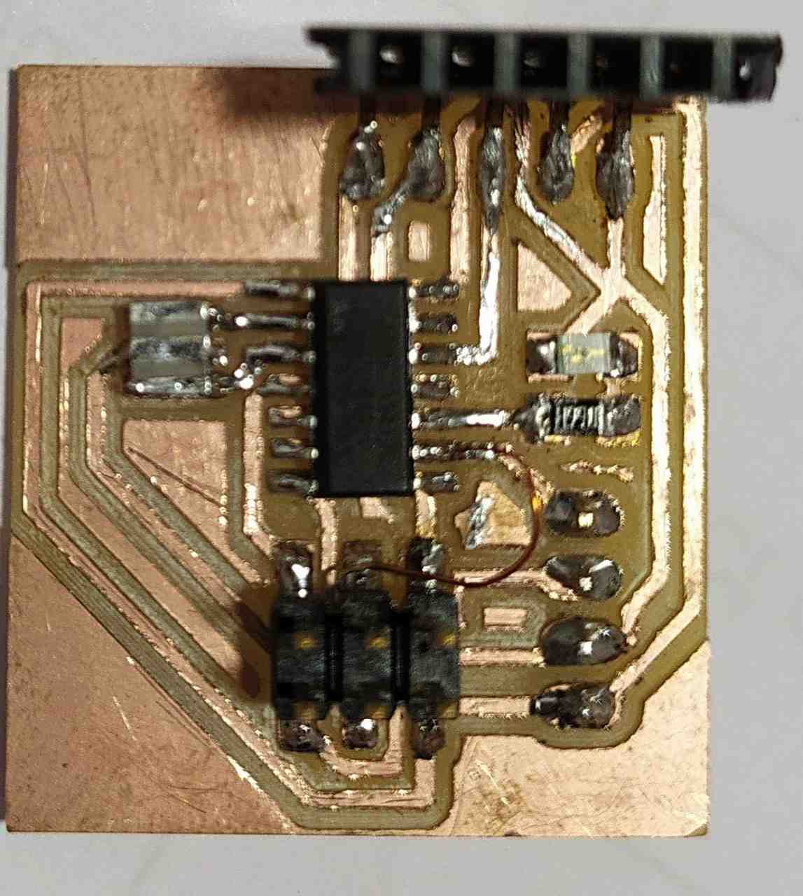
I tried to solve my mistake using copper wire, since it didint work properly. I made a new board.
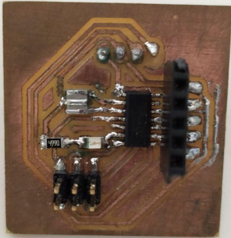
The new board worked perfectely. The board looks old because i took the picture after few months and also due to some error with the bit the trace was not perfect, the side of the trace was bit tampered and i used steel wool to remove and it left scratches on the surface of the board.
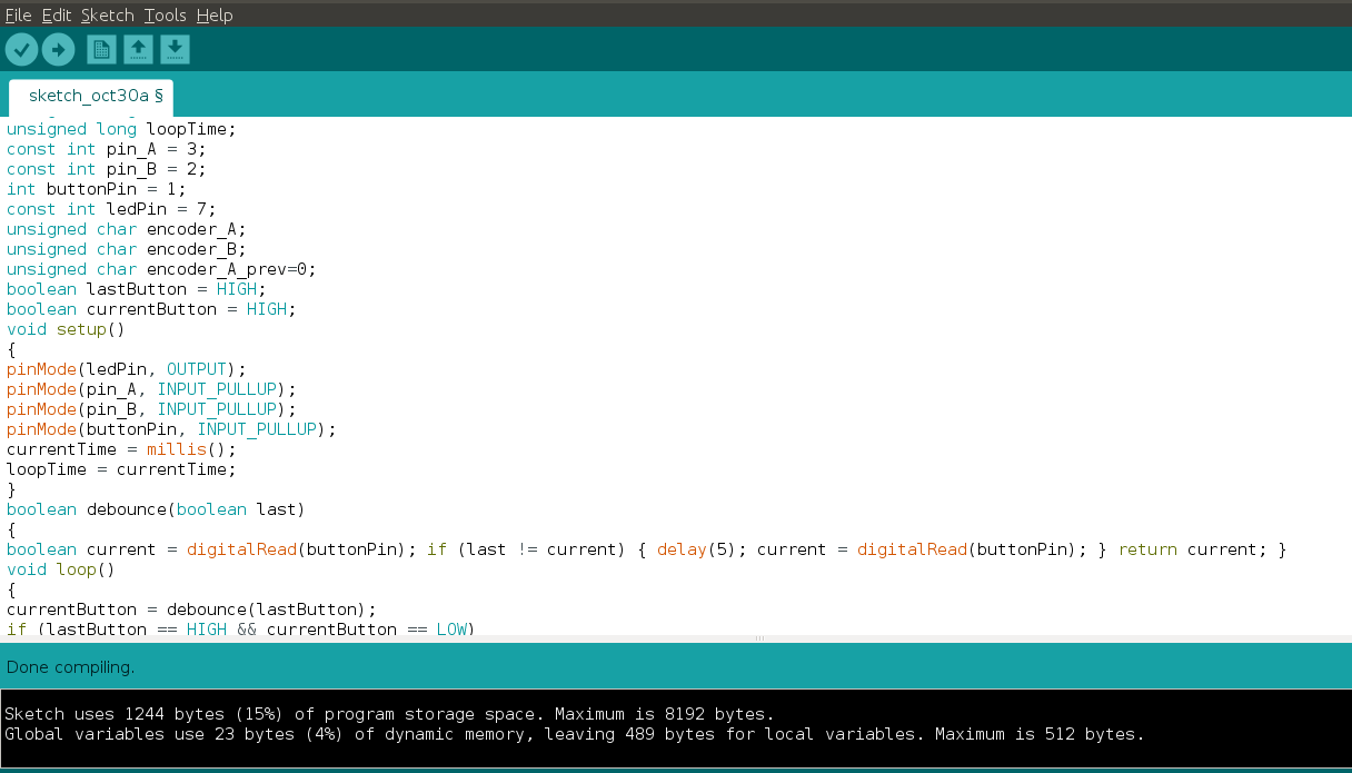
Board programing
I used arduino IDE to program my board. I already placed an LED on the board which can be controlled and can be visually viewed. So i want to change the brightness of led by rotating the shaft and switching it on/off by pressing the shaft.
//
int brightness;
unsigned long currentTime;
unsigned long loopTime;
const int pin_A = 3;
const int pin_B = 2;
int buttonPin = 1;
const int ledPin = 7;
unsigned char encoder_A;
unsigned char encoder_B;
unsigned char encoder_A_prev=0;
boolean lastButton = HIGH;
boolean currentButton = HIGH;
void setup()
{
pinMode(ledPin, OUTPUT);
pinMode(pin_A, INPUT_PULLUP);
pinMode(pin_B, INPUT_PULLUP);
pinMode(buttonPin, INPUT_PULLUP);
currentTime = millis();
loopTime = currentTime;
}
boolean debounce(boolean last)
{
boolean current = digitalRead(buttonPin); if (last != current) { delay(5); current = digitalRead(buttonPin); } return current; }
void loop()
{
currentButton = debounce(lastButton);
if (lastButton == HIGH && currentButton == LOW)
{
brightness = brightness + 255;
}
lastButton = currentButton
if(brightness > 255) brightness = 0;
currentTime = millis();
if(currentTime >= (loopTime + 5))
{
encoder_A = digitalRead(pin_A);
encoder_B = digitalRead(pin_B);
if((!encoder_A) && (encoder_A_prev))
{
if(encoder_B)
{
if(brightness + 5 <= 255) brightness += 5;
}
else
{
if(brightness - 5 >= 0)brightness -= 5;
}
}
encoder_A_prev = encoder_A;
analogWrite(ledPin, brightness);
loopTime = currentTime;
}
}
Download all files.