Fab Academy 2020
Introduction
As in the case of all living beings we are coded into existance and DNA is our code and as in the case of non living materials its also coded based on its geometry, force fields etc. Everything obeys a set of rules and functions only based on these rules. Eventhough we dont know what made these rules happen we have to obey this rule in whatever we make also. In case of electronics the pulse of life is electricity and everything it does is based on how we control this pulse. So this week the main purpose is writing rules to control this pulse. And we have to write this rule which we understand at he same time machine also understands.
Microcontrollers
A microcontroller (or MCU for microcontroller unit) is a small computer on a single integrated circuit. In modern terminology, it is similar to, but less sophisticated than, a system on a chip or SoC; an SoC may include a microcontroller as one of its components. A microcontroller contains one or more CPUs (processor cores) along with memory and programmable input/output peripherals. Program memory in the form of ferroelectric RAM, NOR flash or OTP ROM is also often included on chip, as well as a small amount of RAM. Microcontrollers are designed for embedded applications, in contrast to the microprocessors used in personal computers or other general purpose applications consisting of various discrete chips like ADC(analog to digital converter),DAC [Digital-to-Analog Converter] etc.[wiki]
AVR Microcontrollers
AVR is a family of microcontrollers developed by Atmel beginning in 1996. These are modified Harvard architecture 8-bit RISC single-chip microcontrollers. AVR was one of the first microcontroller families to use on-chip flash memory for program storage, as opposed to one-time programmable ROM, EPROM, or EEPROM used by other microcontrollers at the time.
Attiny24/44/84
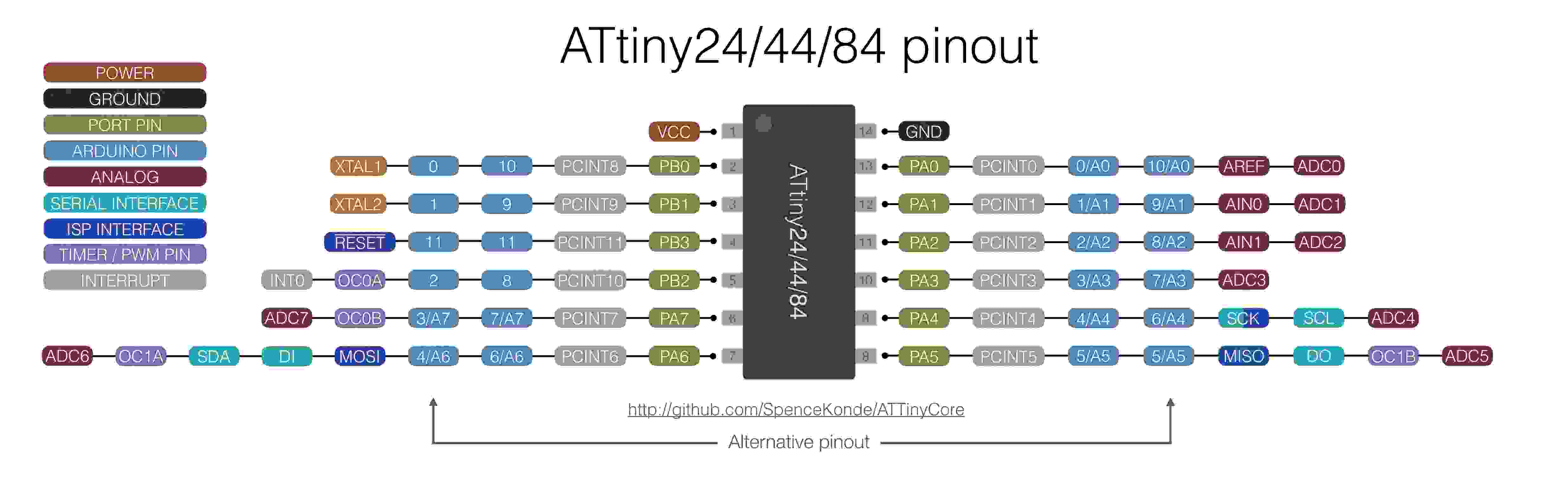
The ATtiny44 is a high-performance, low-power Microchip AVR RISC-based CMOS 8-bit microcontroller.It combines 4KB ISP flash memory, 256-Byte EEPROM, 256B SRAM, 12 general purpose I/O lines .The ATtiny44 consistof 32 general purpose working registers, an 8-bit timer/counter with two PWM channels, a 16-bit timer/counter with two PWM channels, internal and external interrupts, an 8-channel 10-bit A/D converter and a programmable gain stage (1x, 20x) for 12 differential ADC channel pairs. It has a programmable watchdog timer with internal oscillator.The a internal calibrated oscillator and three software selectable power saving modes makes it suitable for small embedded products . By executing powerful instructions in a single clock cycle the device achieves throughputs approaching 1 MIPS per MHz .It also balance power consumption and improve processing speed. More details cab be found in the datasheet .
- VCC Supply voltage
- GNDGround
- Port B (PB3...PB0)Port B is a 4-bit bi-directional I/O port with internal pull-up resistors (selected for each bit). As inputs, Port B pins that are externally pulled low will source current if the pull-up resistors are activated.so we don't need to add a pull-up resistor externaly for button's and other purpose.
- RESETReset input. A low level on this pin for longer than the minimum pulse length will generate a reset, even if the clock is not running.a reset will just reset the programm that currently runnig .
- Port A (PA7...PA0)Port A is a 8-bit bi-directional I/O port with internal pull-up resistors (selected for each bit). As inputs, Port A pins that are externally pulled low will source current if the pull-up resistors are activated
datasheet basics of various attiny
As from previous weeks usbtiny was fabricated in electronic production week and hello echo board was fabricated in the electronic designing week
Arduino
Arduino is an open-source platform used for building electronics projects. Arduino consists of both a physical programmable circuit board (often referred to as a microcontroller) and a piece of software, or IDE (Integrated Development Environment) that runs on your computer, used to write and upload computer code to the physical board.
Ardunio is basically AVR C with an extra layer on top of it. For beginners like me Arduino is relatively easier to learn than AVR C. This is because in the Arudino IDE most of the common tasks we have to do are written as functions and stored in the Arduino library. This makes it easier for beginners as all we have to is call the right functions and the program will work accordingly. But a downside of this is that, the chip will work much slower than if it was programmed with AVR C the reason is that Arduino loads a lot of unused libraries into the chip which will waste many clock cycles. Another problem is the size of the program itself, this will be much larger in comparison with AVR C program.
Group Assignment
The group assignement for this week is explained in detail in the group page. To access the group page click here.
Programing attiny84 with ARDUINO
THe software can be freely Downloadedfrom arduino website. Relatively easy installation process.
Since the original Arduino software does not support the ATtiny84. I have to add some Board directorys for adding my ATtiny84 board to my arduino enviournment
For that click File => Preference
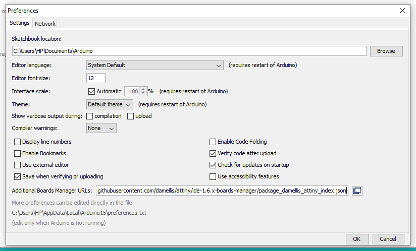
Once the preference tab is open. There is a window to enter the link to the directory to download the library. The link can be found here.
After adding the URL
Click on Tools => Board => Board manager
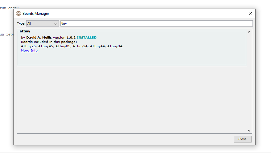
Search for Attiny84 in the search window in the newly opened tab. Install the file when it is shown. Now the arduino has instructions for attiny84.
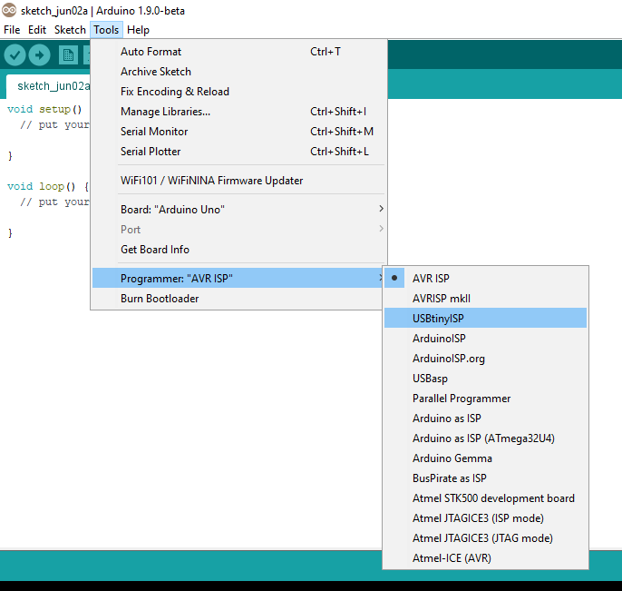
We are using Fab ISP to programme the Hello-Echo board so Select the Programmer as USBtinyISP.
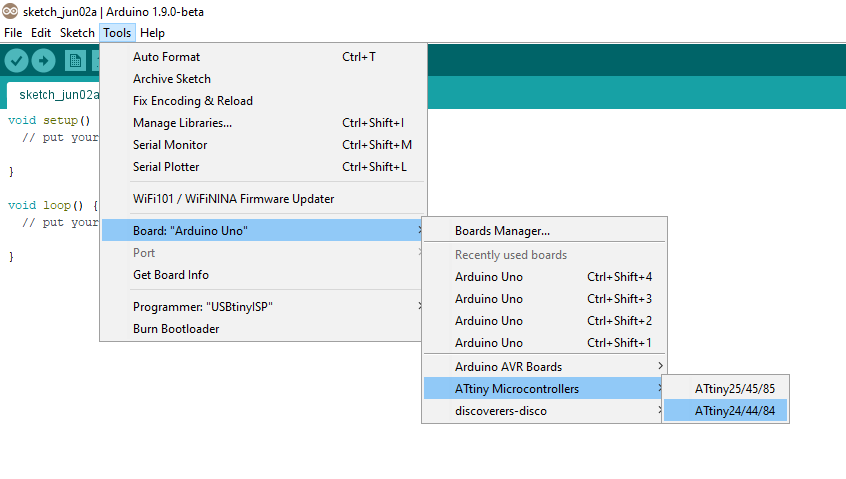
Now you can select ATtiny84 under the ATtiny Microcontrollers in board Selection
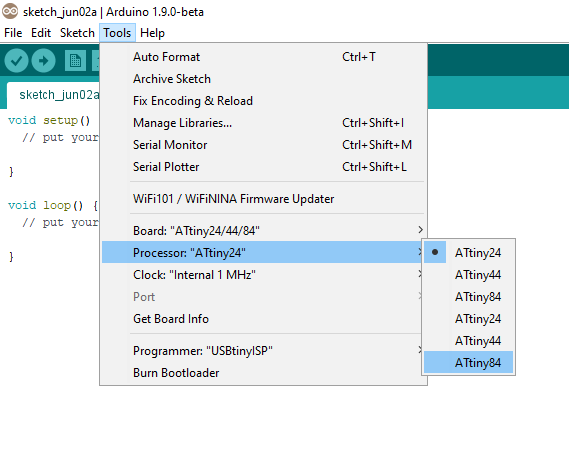
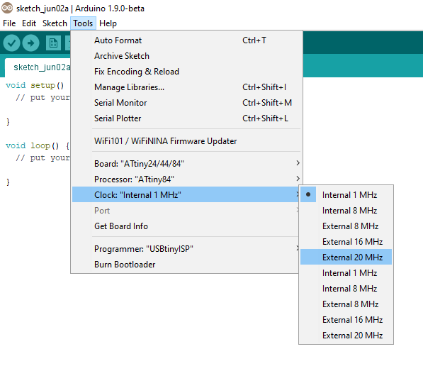
Select appropriate Clock and Programmer.
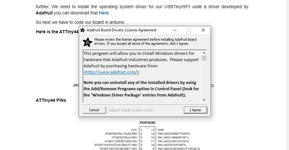
We need to install the operating system driver for our USBTinyISP for windows.I used a driver developed by Adafruit you can download thatHere
Arduino code
Arduino program to blink LED in fixed intervals.
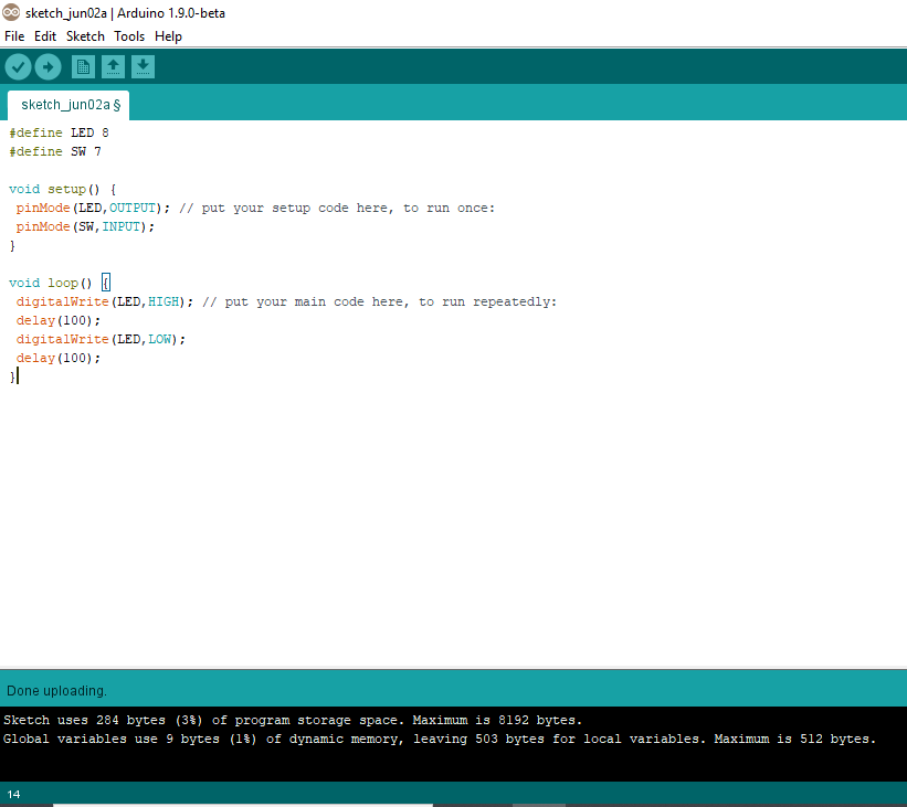
#define LED 8
#define SW 7

void setup() {
pinMode(LED,OUTPUT); // put your setup code here, to run once:
pinMode(SW,INPUT);
}

void loop() {

digitalWrite(LED, HIGH);
delay(100);

digitalWrite(LED, LOW);
delay(100);
}
Before uploading the program to our board.We have to tell our IDE some more things.
ATTiny84 is defaultly set to use the Internal clock .So if you are using Arduino to program it. It will not get program initially . We have to upload the Bootloader first.
Arduino program to switch on/off an led
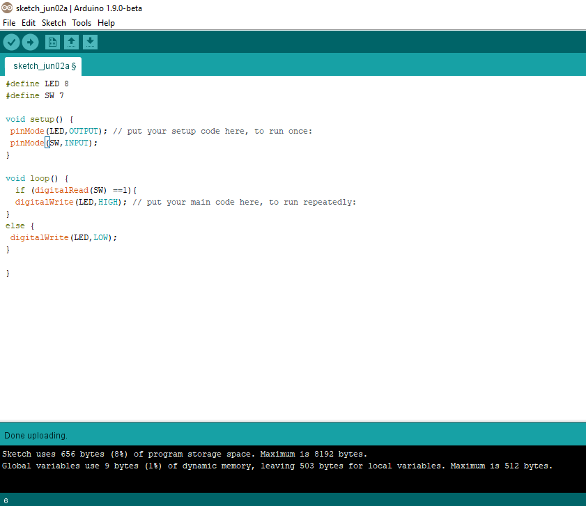
#define LED 8
#define SW 7

void setup()
{
pinMode(LED,OUTPUT); // put your setup code here, to run once:
pinMode(SW,INPUT);
}

void loop() {
if (digitalRead(SW) == 1) {
digitalWrite(LED, HIGH);

}
else {
digitalWrite(LED, LOW);

}
}
Arduino programe to blink in a pattern.
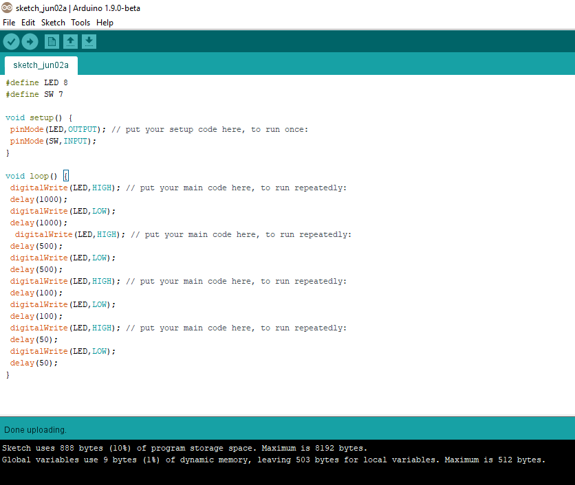
#define LED 8
	#define SW 7

	void setup() {
	pinMode(LED,OUTPUT); // put your setup code here, to run once:
	pinMode(SW,INPUT);
	}

	void loop() {

	digitalWrite(LED, HIGH);
	delay(1000);
	digitalWrite(LED, LOW);
	delay(1000);
	digitalWrite(LED, HIGH);
	delay(500);
	digitalWrite(LED, LOW);
	delay(500);
	digitalWrite(LED,HIGH);
	delay(100);
	digitalWrite(LED, LOW);
	delay(100);
	digitalWrite(LED,HIGH);
	delay(50);
	digitalWrite(LED, LOW);
	delay(50);

	}
Arduino programe to fade led light.
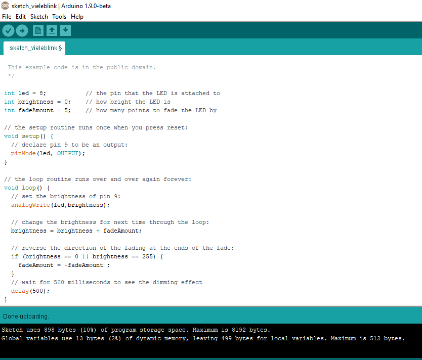
/*
	Fade

	This example shows how to fade an LED on pin 8 using the analogWrite()
	function.

	The analogWrite() function uses PWM, so if you want to change the pin you're
	using, be sure to use another PWM capable pin. On most Arduino, the PWM pins
	are identified with a "~" sign, like ~3, ~5, ~6, ~9, ~10 and ~11.

	This example code is in the public domain.

	http://www.arduino.cc/en/Tutorial/Fade
  */

  int led = 8;           // the PWM pin the LED is attached to
  int brightness = 0;    // how bright the LED is
  int fadeAmount = 5;    // how many points to fade the LED by

  // the setup routine runs once when you press reset:
  void setup() {
	// declare pin 8 to be an output:
	pinMode(led, OUTPUT);
  }

  // the loop routine runs over and over again forever:
  void loop() {
	// set the brightness of pin 8:
	analogWrite(led, brightness);

	// change the brightness for next time through the loop:
	brightness = brightness + fadeAmount;

	// reverse the direction of the fading at the ends of the fade:
	if (brightness <= 0 || brightness >= 255) {
	  fadeAmount = -fadeAmount;
	}
	// wait for 500 milliseconds to see the dimming effect
	delay(500);
  }
The main important steps and how to write a code using arduino
Atmel 7 studio
Studio 7 is the integrated development platform (IDP) for developing and debugging all AVR® and SAM microcontroller applications. The Atmel Studio 7 IDP gives you a seamless and easy-to-use environment to write, build and debug your applications written in C/C++ or assembly code. It also connects seamlessly to the debuggers, programmers and development kits that support AVR® and SAM devices.
Additionally, Studio includes Atmel Gallery, an online app store that allows you to extend your development environment with plug-ins developed by Microchip as well as third-party tool and embedded software vendors. Studio 7 can also seamlessly import your Arduino sketches as C++ projects, providing a simple transition path from Makerspace to Marketplace.
In Atmel Studio we are writing C code. In order to use the Atmel Studio with our Fab ISP we need to configure the studio before use.
Embedded C,C++
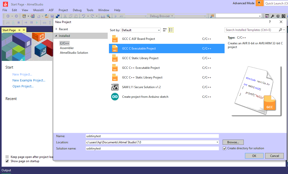
To start a new project. Just open the software and choose new project. Select Gcc C Executable Project .Then select a name and click Ok. Select the chip from the next window and click on the okay button. Now the environment is created.
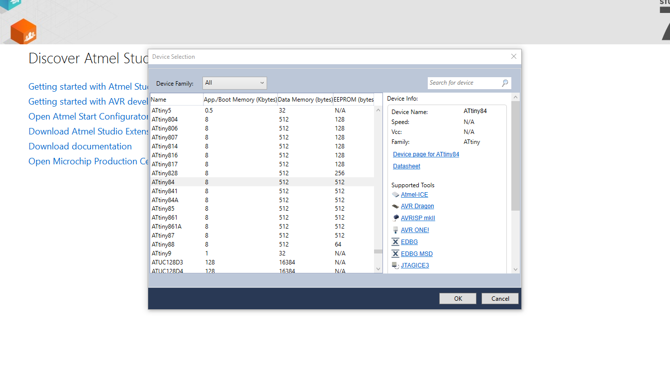
After the initial step we need to select our target microcontroller after selcting that we have created our atmel enviornment.
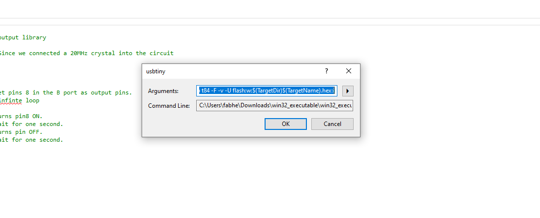
Next we have to add our programmer to our enviournment. Choose Tools => External Tools fill the spaces as shown below.
USBTinyavrdude.exe-c usbtiny -p attiny44 -U flash:w:$(ProjectDir)Release\$(TargetName).hex:iIf don't have the Avrdude (you can check it by typing Avrdude in cmd) just download and install the WinAVR here you can download it
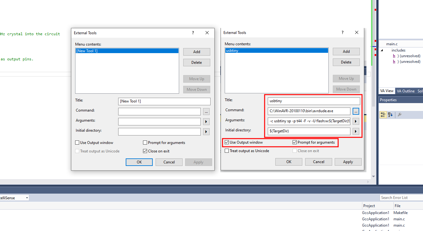
A small window appears and press ok and check if USBtiny is added as a tool.
DDRx DDR stands for Data direction Register, basically it is an 8-bit register which determines whether one pin will be an input or output pin. If you want the pin you connected to the LED to be set as output, then you should give that value as 1 on DDRx. Example I connected my LED to PB2, hence I have to make it as out put in DDR2. Hence I give the code to set the pin PB2 as out put by writing. DDRA=0xff; This is HEX equivalent for DDRB=ob11111111 What it does is that it will set all the pins on the PB2 as output pins.
PORTx while DDRx denotes the direction of the Pin, PORT denotes the state of it. That means if I give a value 1 in the PORT register of that pin It would be set to HIGH, or 5V in case of the micro controller.
PINx register is a dynamic register whose value will be automatically updated based on the received values of the sate of all pins, so 5V to that pin will write 1 to that register.
I made a simple led blinking program.
#include avr/io.h>                    // AVR input/output library

#define F_CPU 20000000                 // Since we connected a 20MHz crystal into the circuit
#include util/delay.h>                // Delay library

main()
{
DDRB = (1 << 2);                   //set pin 2 in the B port as output pins.
while (1)                          // infinte loop
{
PORTB |= (1 << 2);             //Turns pin 2 ON.
_delay_ms(1000);               //wait for one second.
PORTB &= (!(1 << 2));          //Turns pin OFF.
_delay_ms(1000); //wait for one second.Build >> Build Soution
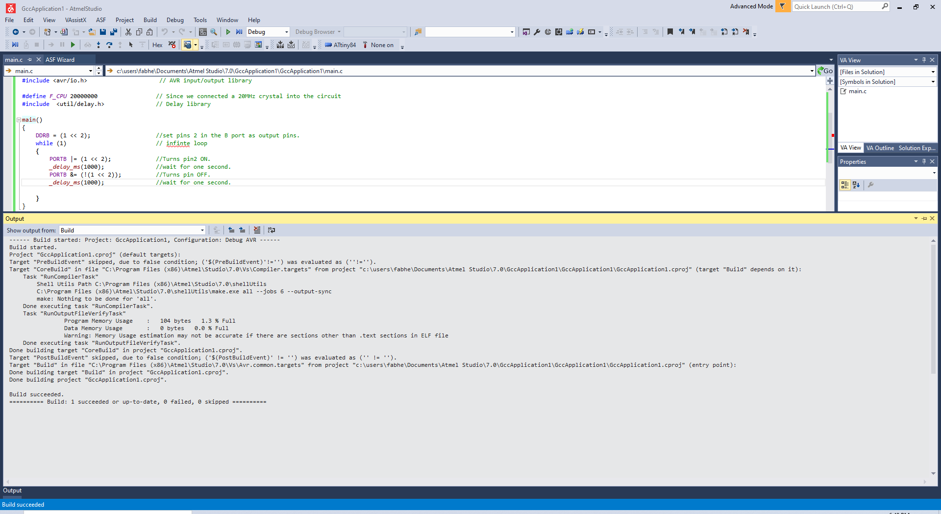
This is the console result.If something wrong happens. It will be displayed here.Once the build solution is success the progrsm is ready for flash.
THe code is flashed to chip using programmer Tools=>USBTinys
The below section is console output. there was no error.
	avrdude.exe: Version 5.10, compiled on Jan 19 2010 at 10:45:23
				 Copyright (c) 2000-2005 Brian Dean, http://www.bdmicro.com/
				 Copyright (c) 2007-2009 Joerg Wunsch

				 System wide configuration file is "C:\WinAVR-20100110\bin\avrdude.conf"

				 Using Port                    : lpt1
				 Using Programmer              : usbtiny
				 AVR Part                      : ATtiny44
				 Chip Erase delay              : 4500 us
				 PAGEL                         : P00
				 BS2                           : P00
				 RESET disposition             : possible i/o
				 RETRY pulse                   : SCK
				 serial program mode           : yes
				 parallel program mode         : yes
				 Timeout                       : 200
				 StabDelay                     : 100
				 CmdexeDelay                   : 25
				 SyncLoops                     : 32
				 ByteDelay                     : 0
				 PollIndex                     : 3
				 PollValue                     : 0x53
				 Memory Detail                 :

										  Block Poll               Page                       Polled
				   Memory Type Mode Delay Size  Indx Paged  Size   Size #Pages MinW  MaxW   ReadBack
				   ----------- ---- ----- ----- ---- ------ ------ ---- ------ ----- ----- ---------
				   eeprom        65     6     4    0 no        256    4      0  4000  4500 0xff 0xff
				   flash         65     6    32    0 yes      4096   64     64  4500  4500 0xff 0xff
				   signature      0     0     0    0 no          3    0      0     0     0 0x00 0x00
				   lock           0     0     0    0 no          1    0      0  9000  9000 0x00 0x00
				   lfuse          0     0     0    0 no          1    0      0  9000  9000 0x00 0x00
				   hfuse          0     0     0    0 no          1    0      0  9000  9000 0x00 0x00
				   efuse          0     0     0    0 no          1    0      0  9000  9000 0x00 0x00
				   calibration    0     0     0    0 no          1    0      0     0     0 0x00 0x00

				 Programmer Type : USBtiny
				 Description     : USBtiny simple USB programmer, http://www.ladyada.net/make/usbtinyisp/
	avrdude.exe: programmer operation not supported

	avrdude.exe: Using SCK period of 10 usec
	avrdude.exe: AVR device initialized and ready to accept instructions

	Reading | ################################################## | 100% 0.00s

	avrdude.exe: Device signature = 0x1e930c
	avrdude.exe: Expected signature for ATtiny44 is 1E 92 07
	avrdude.exe: safemode: lfuse reads as FE
	avrdude.exe: safemode: hfuse reads as DF
	avrdude.exe: safemode: efuse reads as FF
	avrdude.exe: NOTE: FLASH memory has been specified, an erase cycle will be performed
				 To disable this feature, specify the -D option.
	avrdude.exe: erasing chip
	avrdude.exe: Using SCK period of 10 usec
	avrdude.exe: reading input file "c:\users\fabhe\Documents\Atmel Studio\7.0\AssemblerApplication1\AssemblerApplication1\Debug\AssemblerApplication1.hex"
	avrdude.exe: writing flash (16 bytes):

	Writing | ################################################## | 100% 0.02s

	avrdude.exe: 16 bytes of flash written
	avrdude.exe: verifying flash memory against c:\users\fabhe\Documents\Atmel Studio\7.0\AssemblerApplication1\AssemblerApplication1\Debug\AssemblerApplication1.hex:
	avrdude.exe: load data flash data from input file c:\users\fabhe\Documents\Atmel Studio\7.0\AssemblerApplication1\AssemblerApplication1\Debug\AssemblerApplication1.hex:
	avrdude.exe: input file c:\users\fabhe\Documents\Atmel Studio\7.0\AssemblerApplication1\AssemblerApplication1\Debug\AssemblerApplication1.hex contains 16 bytes
	avrdude.exe: reading on-chip flash data:

	Reading | ################################################## | 100% 0.02s

	avrdude.exe: verifying ...
	avrdude.exe: 16 bytes of flash verified

	avrdude.exe: safemode: lfuse reads as FE
	avrdude.exe: safemode: hfuse reads as DF
	avrdude.exe: safemode: efuse reads as FF
	avrdude.exe: safemode: Fuses OK

	avrdude.exe done.  Thank you.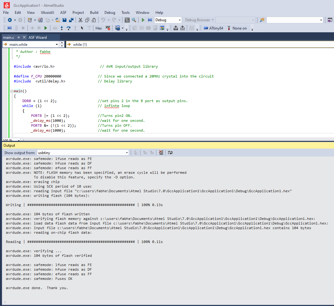
Atmel (assembler)
Assembly language is an alphanumeric representation of machine code.The instructions used in writing programs in assembly language are not general but specific to the microcontroller. Each company provides a set of instructions for there microcontrollers
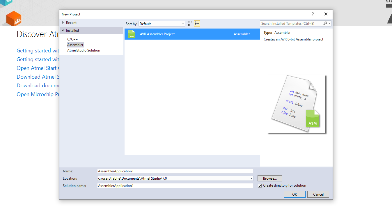
So here we are using Atmel studio to write the Assebler code .First we need to start a project that we did in the C code.After that Select the Assembler in template and Click ok. After that Select our Target Microcontroller, we have ATtiny44.
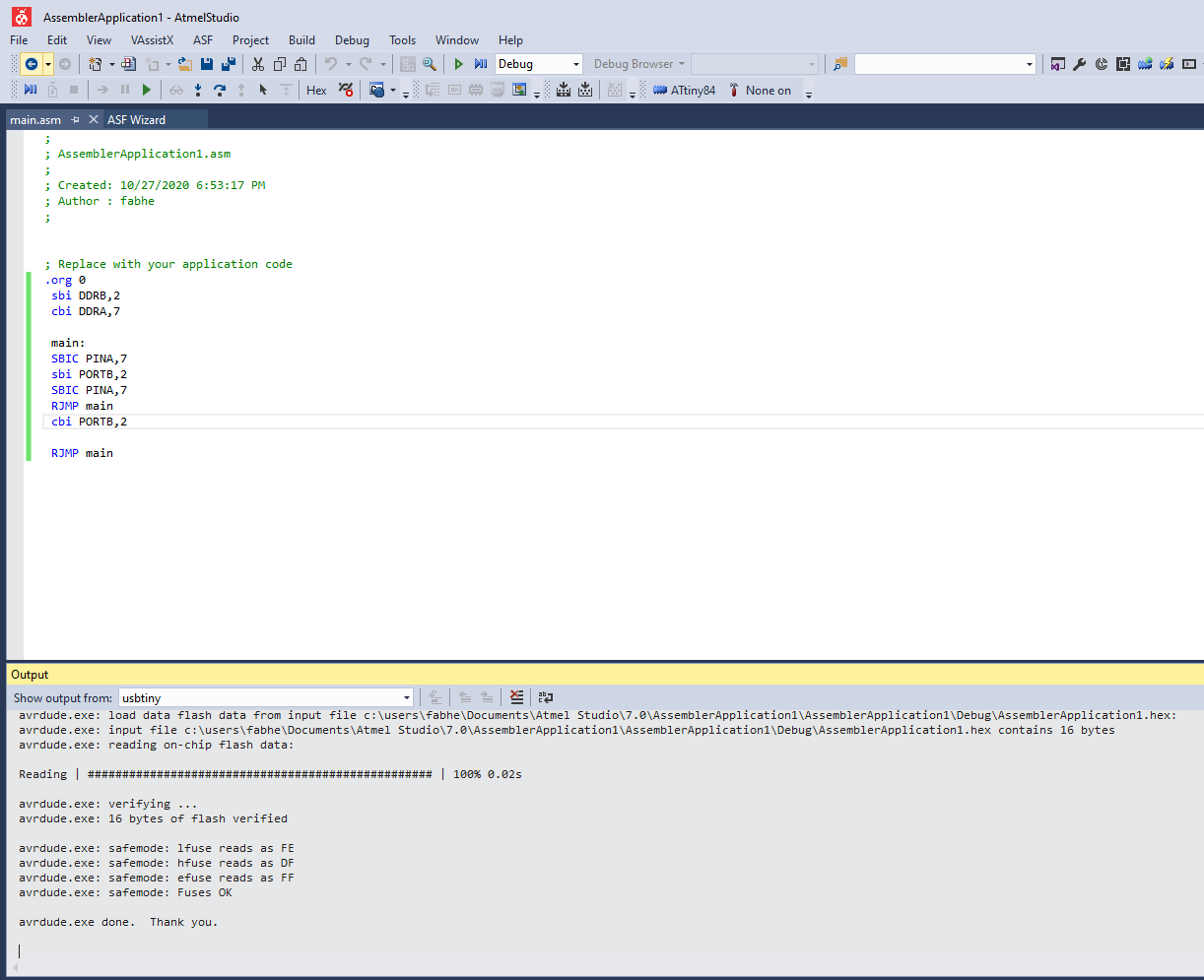
;
	; AssemblerApplication1.asm
	;
	; Created: 10/27/2020 6:53:17 PM
	; Author : fabhe
	;


	; Replace with your application code
	.org 0
	 sbi DDRB,2
	 cbi DDRA,7

	 main:
	 SBIC PINA,7
	 sbi PORTB,2
	 SBIC PINA,7
	 RJMP main
	 cbi PORTB,2

	 RJMP main
This is our Assembler code that will turn on the led when we press the switch.
.org :- it used for set the PC(Programme Counter) in a Specific value, here we set PC in Zerosbi :- Set bit , so here sbi DDRB,2 we set the 2nd bit of B port as 1 , so PB2 will be OUTPUTcbi :- Clear bit , so here cbi DDRA,7 we set the 7th bit of port A as 0,as PA7 will be INPUTmain: :- This is a label name it's like a function, all the code under the label we can get by calling the label nameSBIC :- In here it will skip the next instruction depending on the I/O bit's state, so here it will skip based on the PINA 7 bitRJMP :- Relative Jump , here it will jump into a specfic label's that we have mentioned, so here it will jump to main label.For Uploading code first we need to build/compile it by using Build >> Build Soution
Download all files.