Computer-controlled cutting
For this assignment we are going to use vinyl cutter and laser cutter. Though there are plenty of other cutting techniques: plasma, water, hot wire
By using vinyl and laser-cutter one can create e.g.: pop-up cards, origami, flexible circuits, antennas, 3d parametric assemblys, bendable 3d shapes (living hinges), mechanisms, screen-print stencils, copper for electronics.
Let’s learn how to cut!
I teamed up with Kris, Joris and Marta to make a group assignment which is characterize the machine.
We are goingto work with Trotec Speedy 400 / Trotec Speedy 400 datasheet
The Work area is 1000 x 610 mm
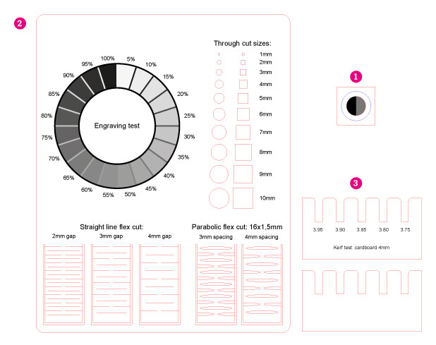
I’ve prepared the test files (among which one was a test file from Thingiverse: https://www.thingiverse.com/thing:728579). We would like to test the laser according to (numbers are refering to the image below):
- Difference in power and speed between cutting-through, drawing a line and engraving. (Here I’ve also put the halfof the circle-line for cut which is touching the ebgraved area- I remember that in thepast the laser which I was using was not recognising the line in such case).
- Engraved shades spectrum (dependant on the intensity of color) and flexability of a solid material one can get by craeting the cutted-out pattern
- Kerf size - means how much of the material is going to be subtracted by the laser while cutting. This is important while creating a
pressfit- the assamblage where the parts are pressed into each other in a stabile way.
I’ve prepared test files in Illustrator. Important is that the cutting-lines have to be in vectors, the for engraving it can be or a bitmap or filled vector shape. The software which is “mediating” between prepared file and Trotec Software - here in FabLab Barcelona - is Rhino. The best file format that you can save from Illustrator to Rhino is .dxf.
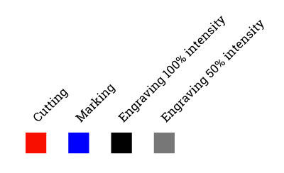
Here the color explanation:
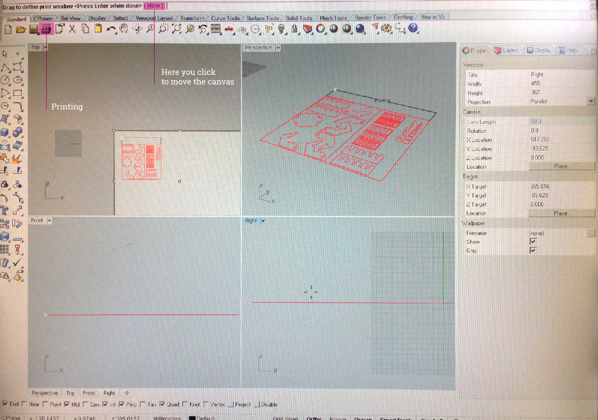
We are starting from opening the design in Rhino. The best is to open new file (
scale should be the same as scale as your design. In my case in both I've set up milimeters).Good practise is to flatten your design before sendingto Job Center. To do that we are selecting the design with selection tool and in the command line on the top we are writting
Make 2D.We are sending the design to Print (click on the floppy disk icon or choose Print from File menu)
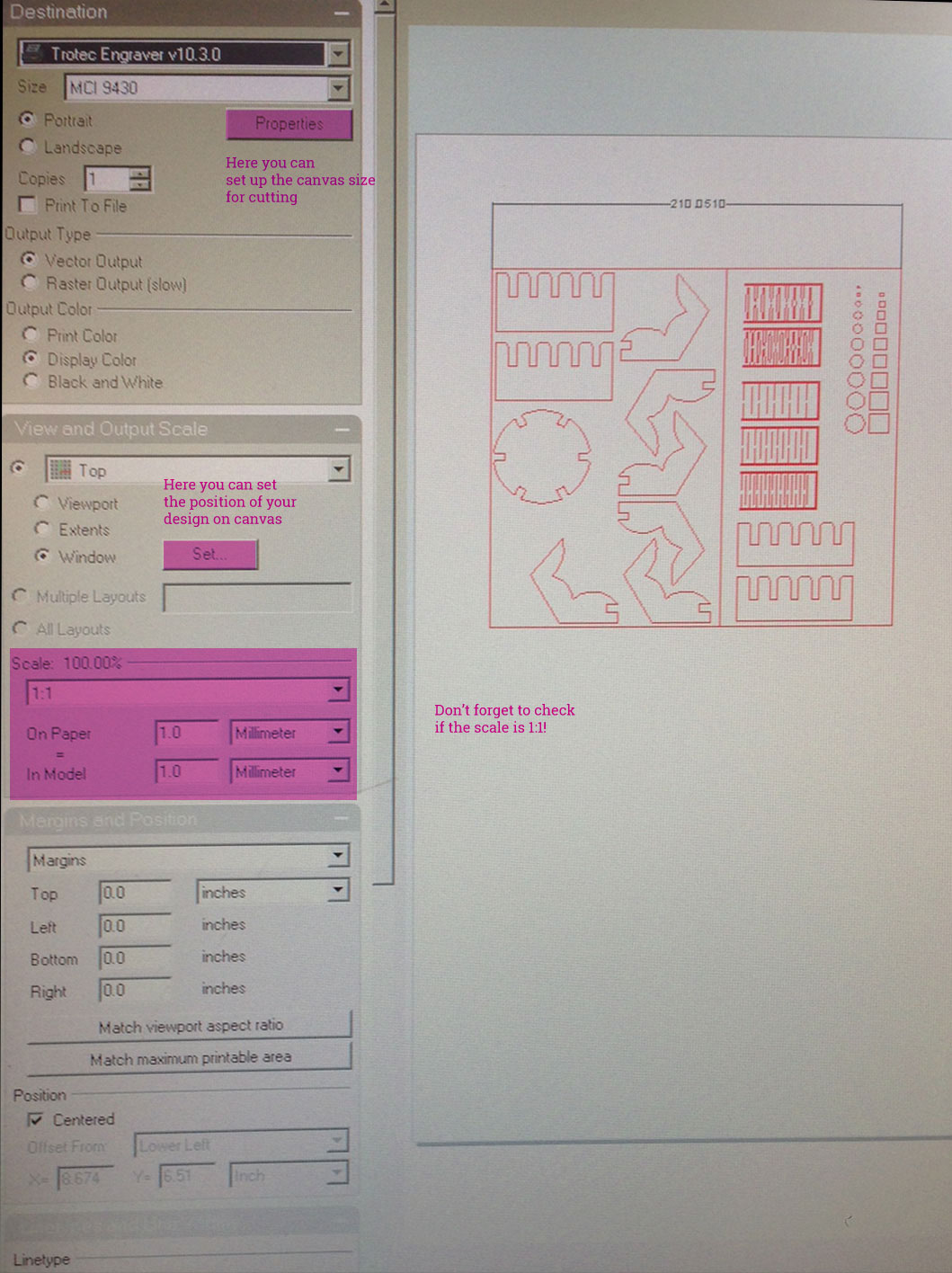
In the Print Window we can set up the
printing area / canvas size.
It's important that this one won't be bigger than the Trotec bed size, otherwise we won't be able to place the file on the virtual printed area in Job Control.
In this window we can also position our design on this printed area -View and Output Scale > Set.
We should check as well isscaleis synchronised - 1:1.
- After clicking
Printthe design will be send to Trotec SoftwareJob Control
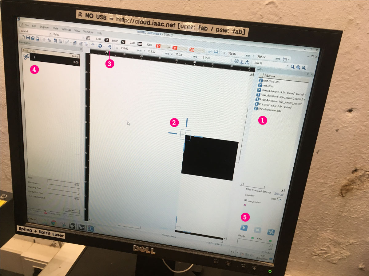
Here are coming next steps of the workflow (numbers corresponding with the image):
1. Your file will be displayed in the file list. You can drag the file to the printing area
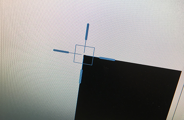
2. Snap the upper-right corner of the file to the pointer. Pointer represents position of the laser on the bed.
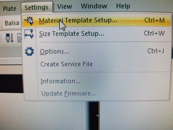
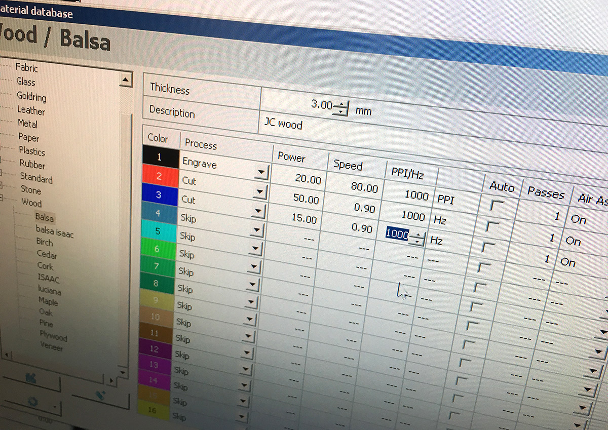
- 3. Set up the cutting/engraving values (click the icon in the top menu, or go to
Settings > Material Template Setup). It’s important to set up in your design different colors for different ways of cutting.Job Controlcan assign different values of power and speed for each color.
- 4. Check if all the colors were analised by the software. Here you will also see the cutting/engraving timing
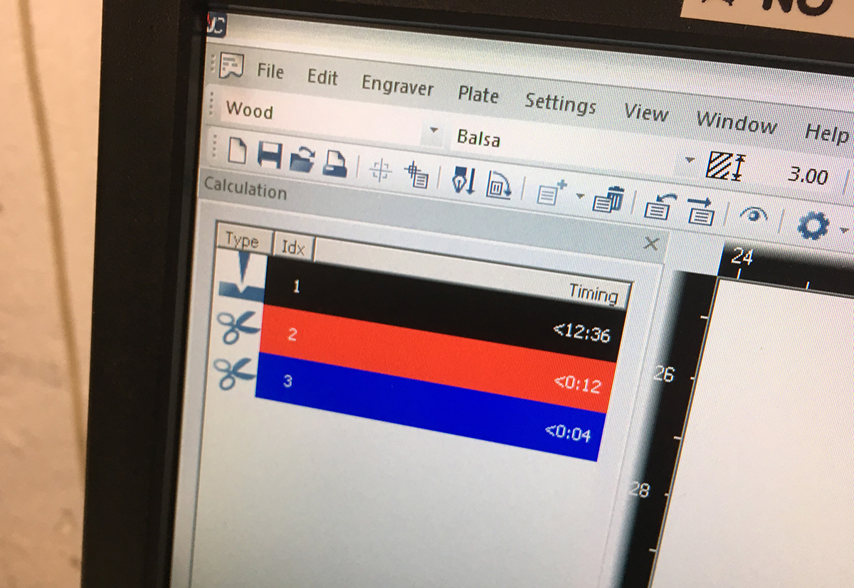
- 5. Start cutting
IMPORTANT: before starting the process of cutting set up the machine!
Tipp: there is a possibility of optimising the way how your laser is cutting the design. Go to top menu > plate > vector ordering
Setting up the machine before starting the cutting process
Turn on the vacuum for the machine
Put your material on the bed
Focus the lense by use of this tool
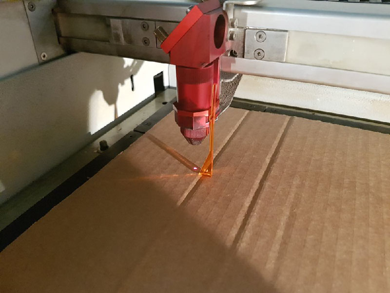
- Close the lid and start cutting process
Pay attention:
- remember about ventilation and air flow when cutting, don’t open the machine up to 2 minutes after cutting (especially plastic materials)
- don’t live the laser alone!
- don’t cut any reflective materials (like metal, aluminium)
- clean the lense
We”ve done several tests with different materials (cardboard,plywood, acrylics). We were mostly focusing on cardboard and on search for the right kerf, since we are going to use this material for creating pressfit construction kit.
Here some photos of results:
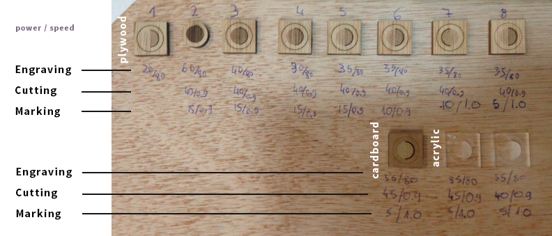
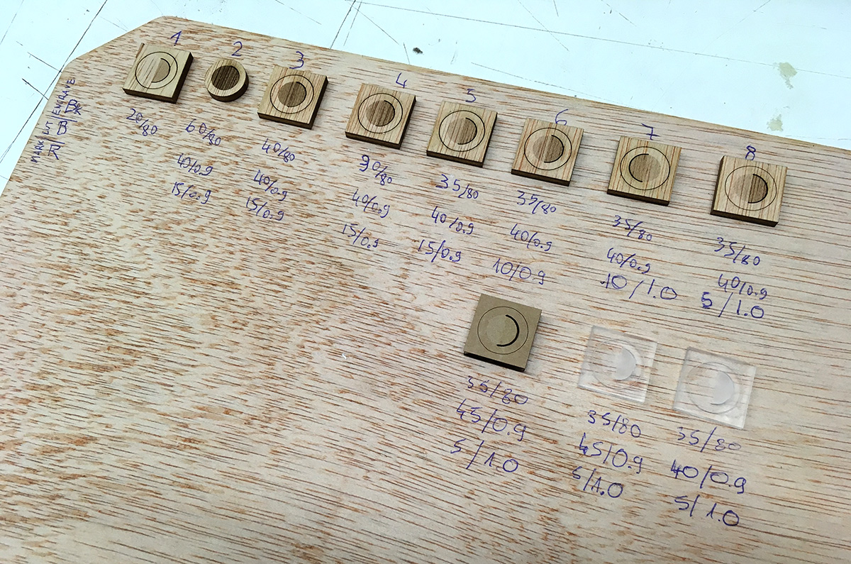
For cardboard 4mm best results one can get with this values:
| operation | power | speed | ||
|---|---|---|---|---|
| engraving | 35 | 80 | ||
| cutting | 40 | 0.9 | ||
| marking | 5 | 1.0 |
For harder materials one should increase the power value. For plywood to 45 and to 50 for acrylics.
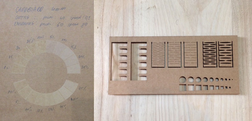
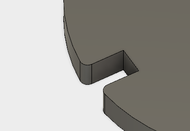
Finding the right kerf
We’ve made a test with different widths of sloths for press-fit kit for 4mm thick cardboard. At the end the one with width 3.75 worked out the best. This one I will use for my cut-outs.
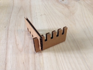
kerf - the amount of subtructed material e.g burnt out by laser. The size after cutting would be a bit bigger than the designed one.
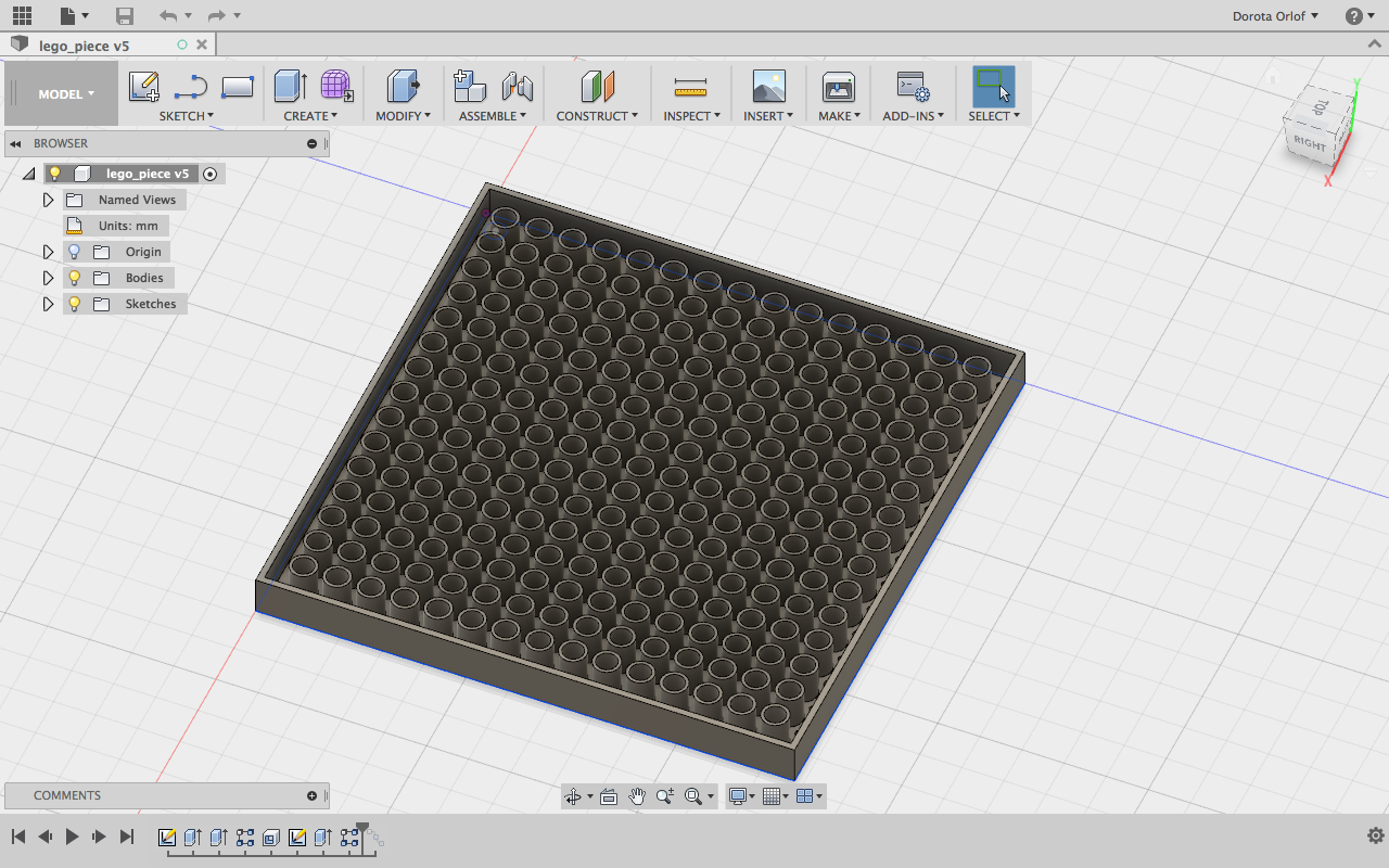
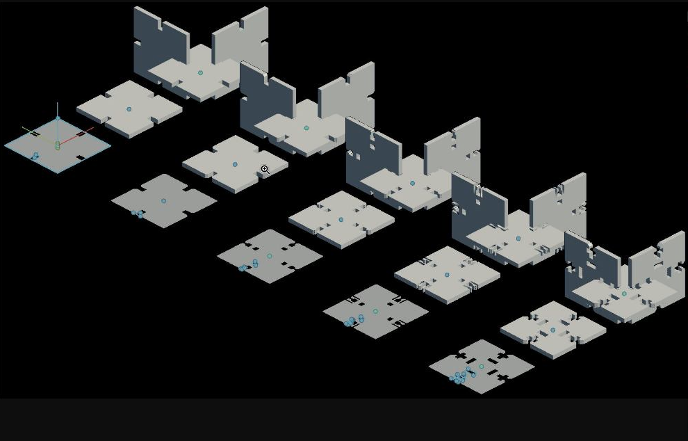
Designing Press fit construction kit in Fusion 360
I’ve attended the introduction Fusion 360 workshop with Ferdi, and managed to build my own parametric lego-brick. It’s afirst time that I’ve created sth parametric! It’s a great and powerful feature ifyou work with materials which parameters are varying (e.g differnt thickesses, different amount of sloths etc.)
Here link to tutorial for refreshing: https://www.youtube.com/watch?v=6d2p6RXOMtA)
Important things that I’ve learnt about Fusion and parametric option:
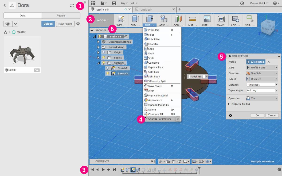
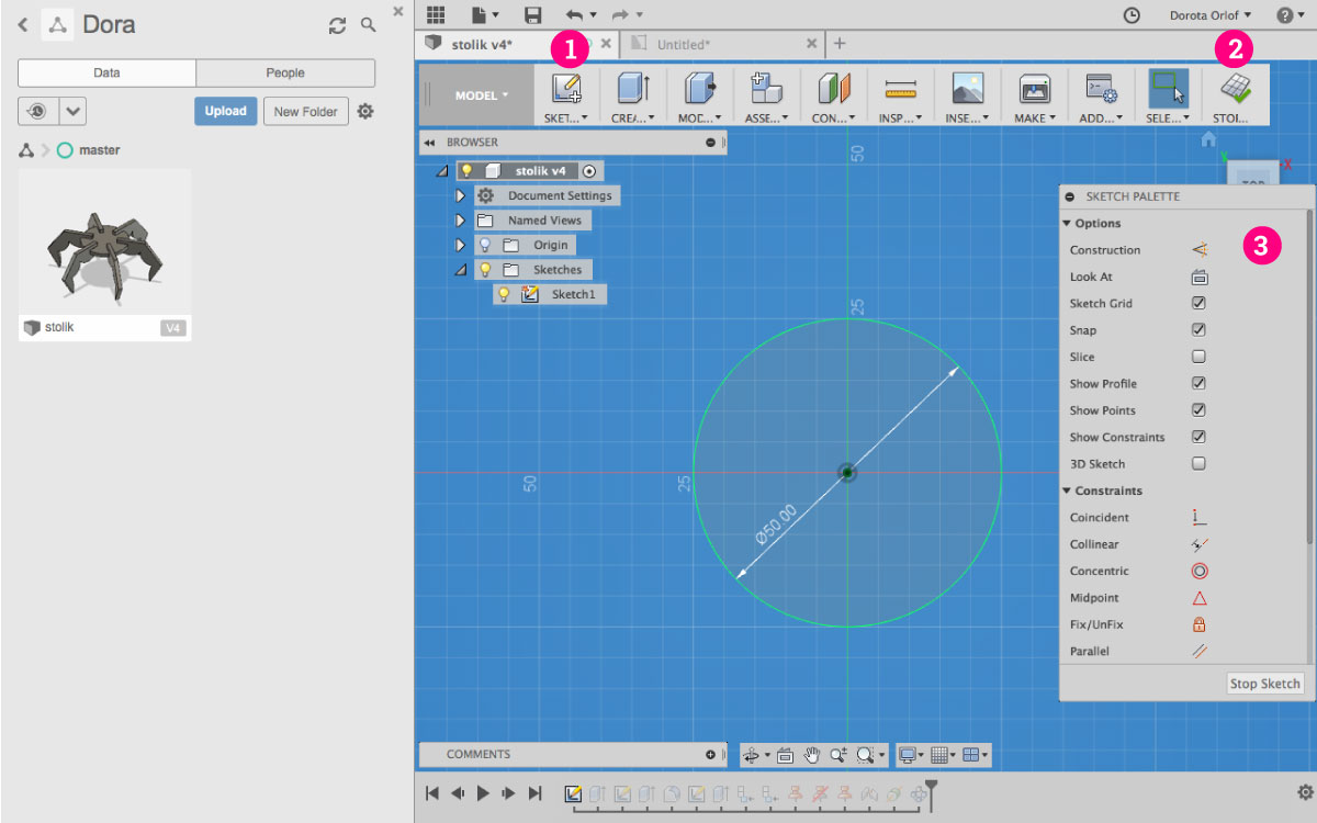
- Here is place for your projects. All the files made in Fusion are stored in Fusion cloud-based platfrom. You can acces them, share, combine or delete from this panel.
- Top menu contains changabele features depending in which
modeare you (gray field “Model”). Here you can change the mode from Model to e.g. Cam or Drawing 2D. Design Historyis storing all the steps thay you’ve made during designing process. It includes creating the objects as well as applying the features. You can always go back and edit the future by doble-clicking on the thumbnail.- In expandable
Modifymenu you can find important featureChange Parametersfor parametrising your design. - Window for editing the feature
- The list of objects / components / sketches
You always start from ceating a 2D sketch, onwhich later you are going to apply features. For each part of the design you are going to create new sketch. On the sketch level the layout will slightely change:
- Click here to
add a new sketchand enter the sketch mode - Clisk here to
exit the sketch mode Constrains panel- you can apply constrains (e.g parallel, colinear, symmetrical) to your sketch
Here some important steps in creating my parametric construction-kit:
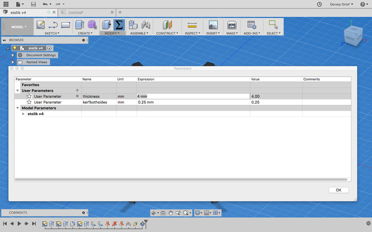
- Set up the changable parameter like “width” in
- Modify - Change Parameter
This parameter will be changable and will influence other, so they will fit together. I’m going to work with width of the cardboard, which will stay in relation with width of the cutted-out slot (they will have the same value).
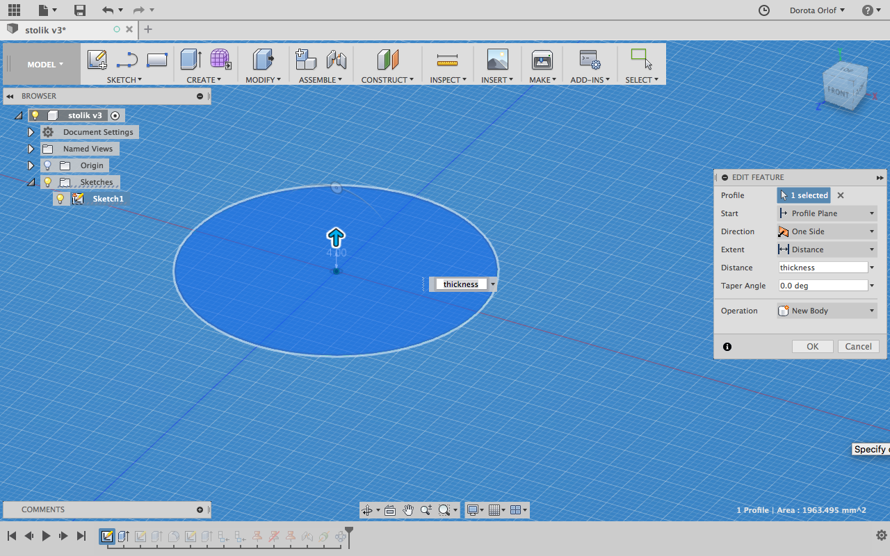
- After creating the sketch use
Extrudeand apply parameter of materialthickness
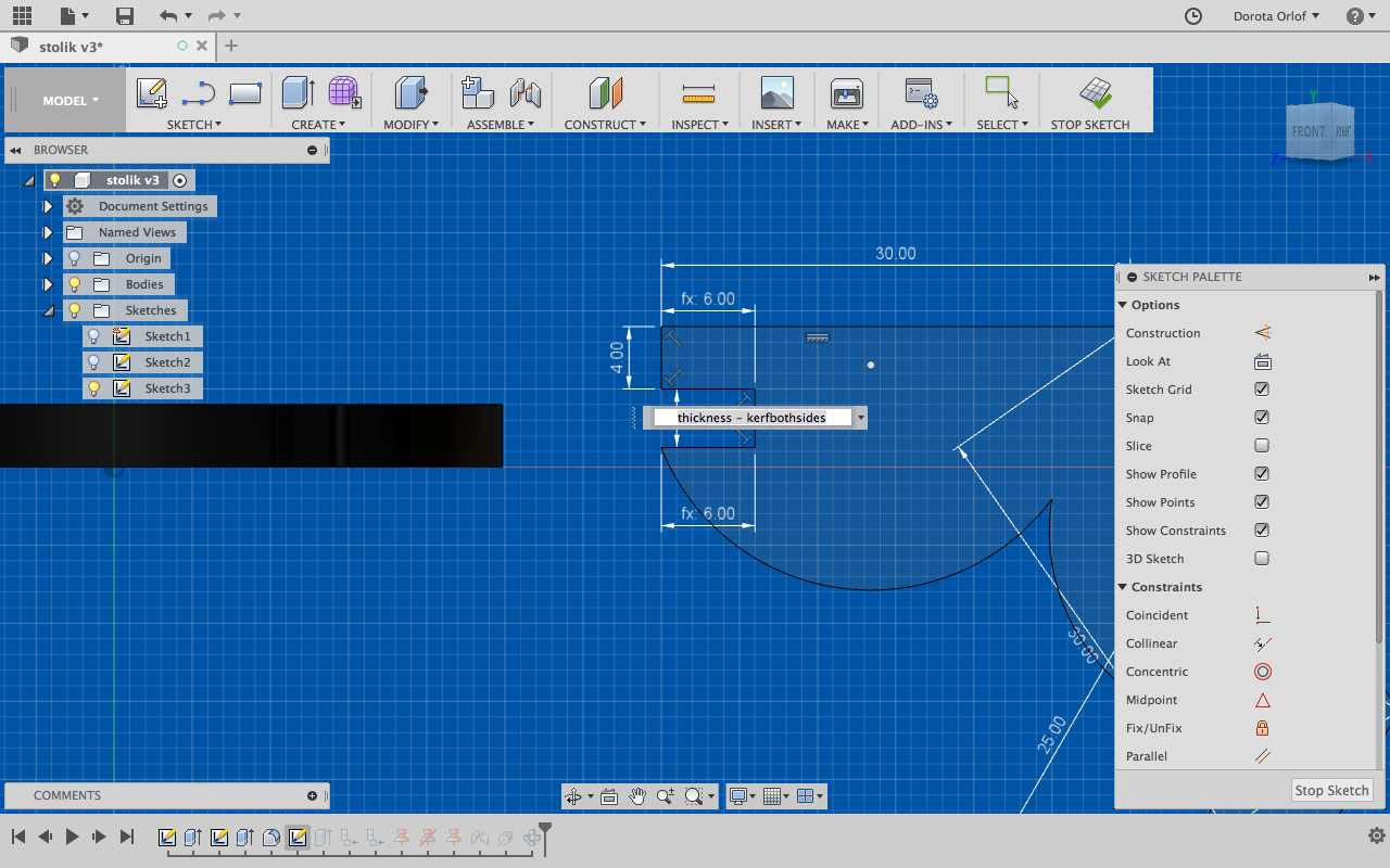
- While creating the slots forpress-fitting apply the width (material thickness) - kerf, so they will fit in a stabile way.
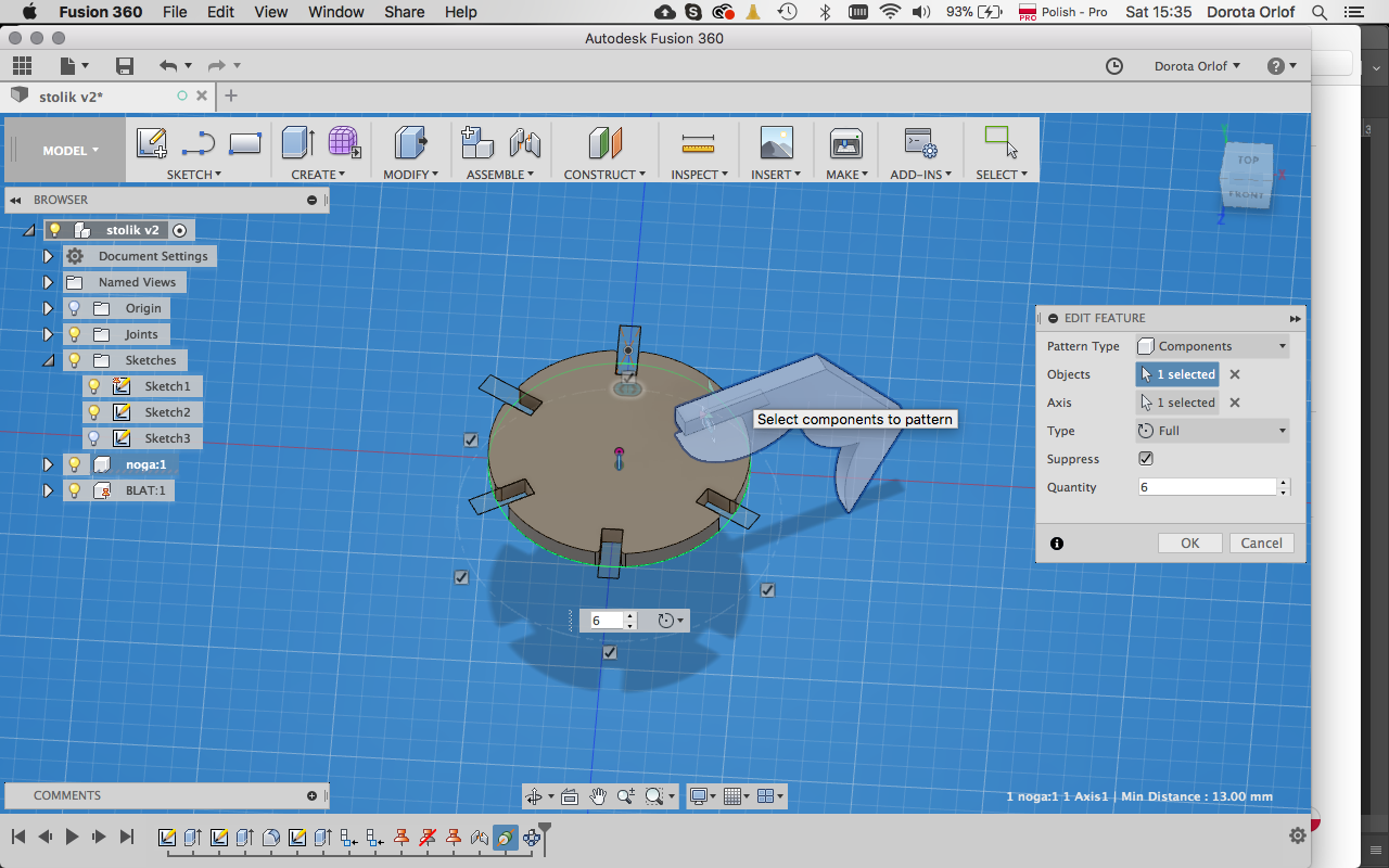
- After creating main component and repeatable element use feature
Circular Patternto multiply and distribute the elemnts around the previousely madeAxis Through Cilinderconstrain.
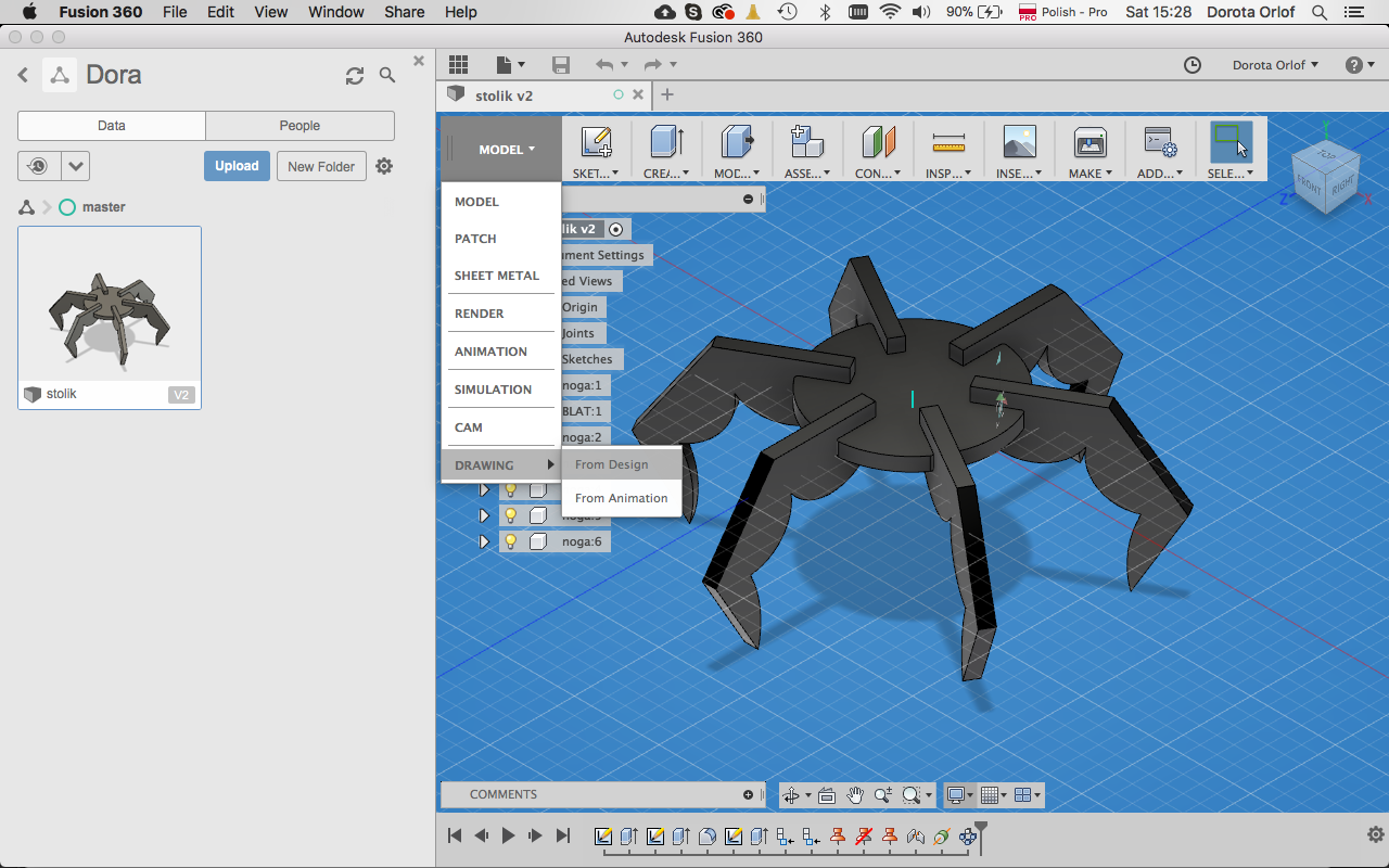
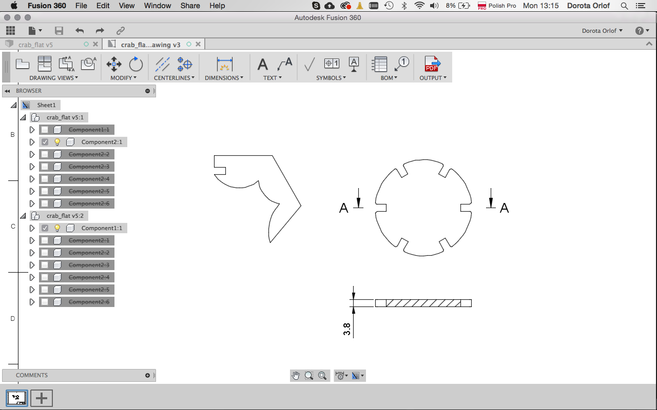
- Ifyou want to export the 2D flat elements for lasercutting, you can useoption
Drawing. Right click on the component andcreate drawing. Than set up the view in drawing file. The best practice while preparing files forlasercutter is to save in pdf, open in illustrator, check and save as dxf.
Other remarks:
- In object mode apply all features:
extrusion(operation:cut),fillet(select edges) - Create each part as a component - when drawing in one file (this good if working with related parameters) than to assamble one have to convert bodies to components (right mouse click)
assamble-joint-type-planar(plane to plane)construct-axis through cilinder(since the element is cylindrical), this give as axis around which we can build the circular pattern (from second component)- right click on the layer with first componenet -
ground- it will fix the comp. in place
Last stepis to send .dxf file to lasercutter, set it up and get this:
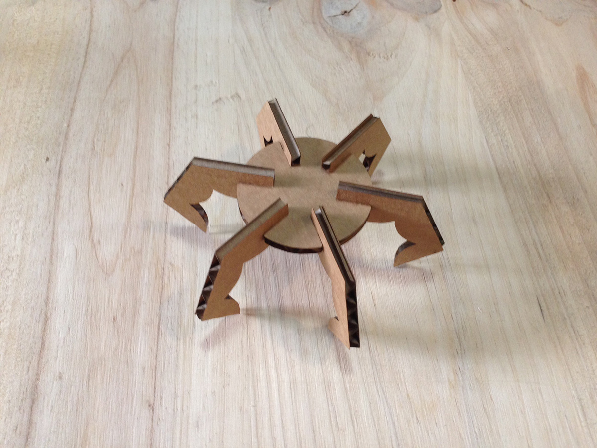
yupiiiiiii!
Vinyl-cutting
Vinyl cutter is great for cutting stickers, designs for heat-pressing on textiles, andother materials which are not suitable for e.g. laser like reflective materials or materials emitting toxic vapors after burning.
In our lab we are using Roland GS-24 vinyl cutter
Specification:
Cutting length: 25 m (max)
Cutting width: 50-700 mm
Cutting force: 30 to 250gf
Materials suitable for the machine: Vinyl, Flexible Copper Paper, Cloth, plastic sheets and other materials
The software operating the our vinyl cutter is called CutStudio.
Setting up the machine:
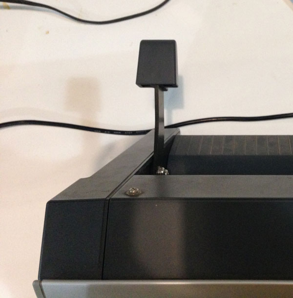
- First you have to place your meterial in the machine. The hinge at the backof the machine has to be down which willl lift up the rolls.
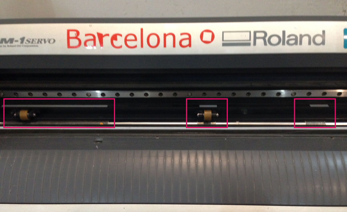
- The rolls (and your material under them) always has to be in between two of this three spots, marked with white tape.
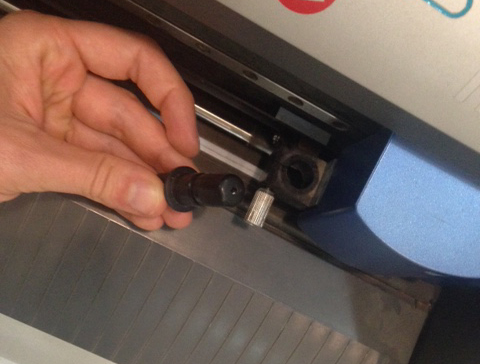
- You can also adjust the blade by turning the bladeholder and unreveal the blade.
- Now one have to switch on the vinyl cutter and measure the sheet of the material. The machine will do it automatially, though one has to choose on the display one of the options of the measuring
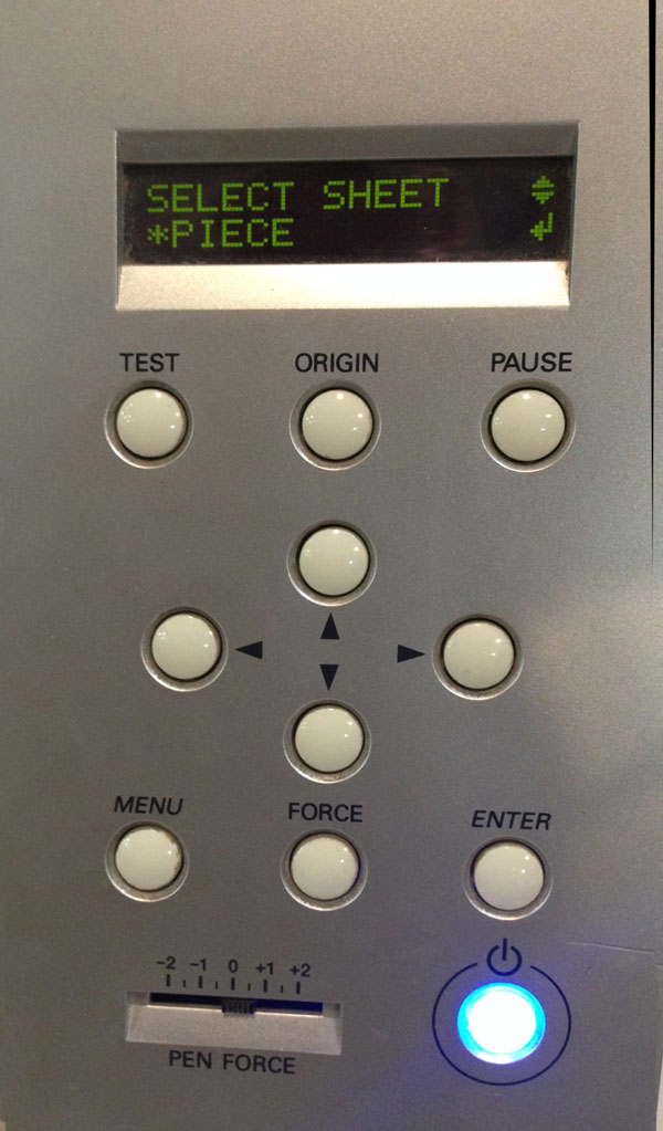
Menu > Unsetup > choose one of options below:
- piece (machine will measure the sheet and set up the artboard in CutStudio)
- roll (when you have a roll, machine will measure the width)
- edge (leaves the knife in the right-down edge of the piece)
Im choosing the piece, and make a test cut to see if it’s enough deep (long clickon Test button). If the test is not satysfing you can adjust the Pen Force atthe bottom of the panel, left from Power Button.
Everything works fine so I’m getting to the software part!.
CutStudio
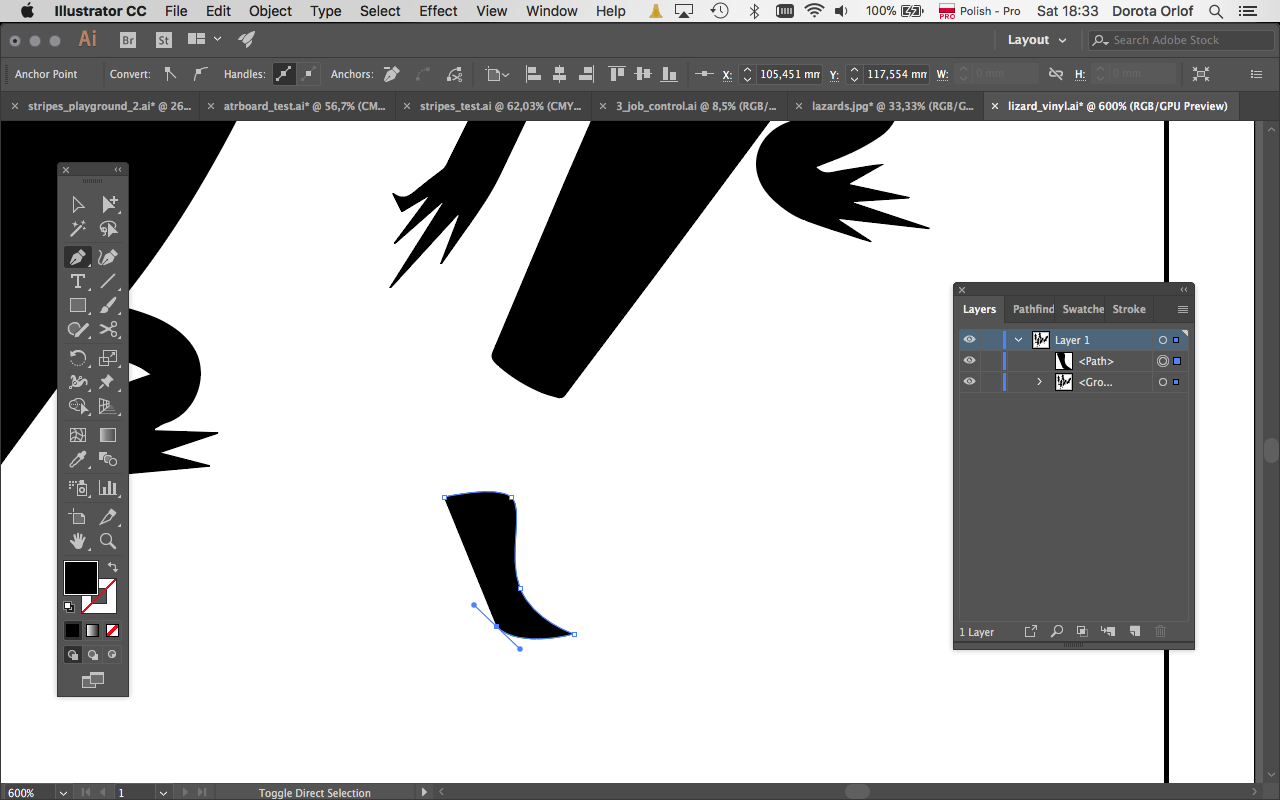
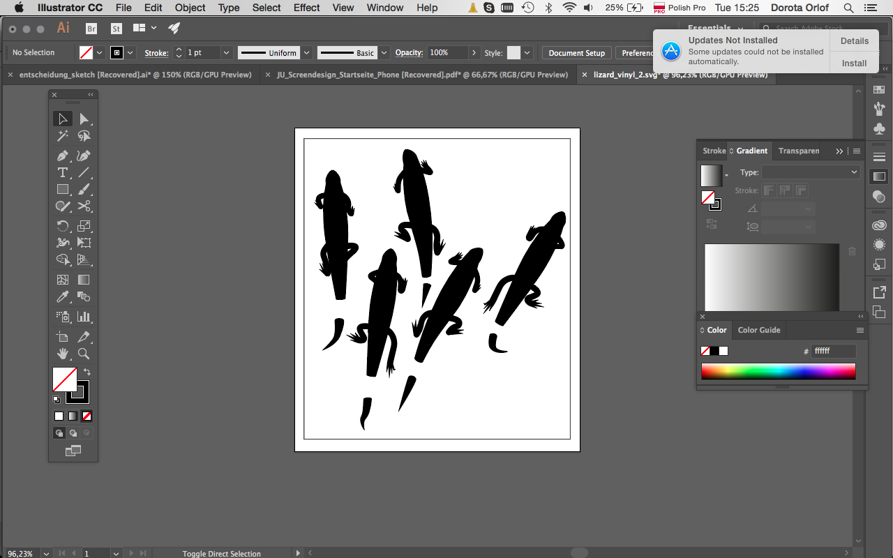
For vinyl-cutting you need to design the file in vector format. I designed the lizards-pattern in Illustrator. As described in the 2D softwae section in previous assignment Computer-aided Design I was constructing the shapes by using mostly Pen Tool. Than I’ve copied one shape and modify slightly so the lizards will look different.
I’ve also made a border around the design so the sticker is going to be cutted out from the rest of the foil sheet.
CamStudio ia pretty old programm thus do not support newer formats of the file types. If you want to import design in CatStudio make sure you’ve prepared it in Illustrator 8 or eps 8 file format.
CutStudio workflow:
- Import the file in one of the format described above
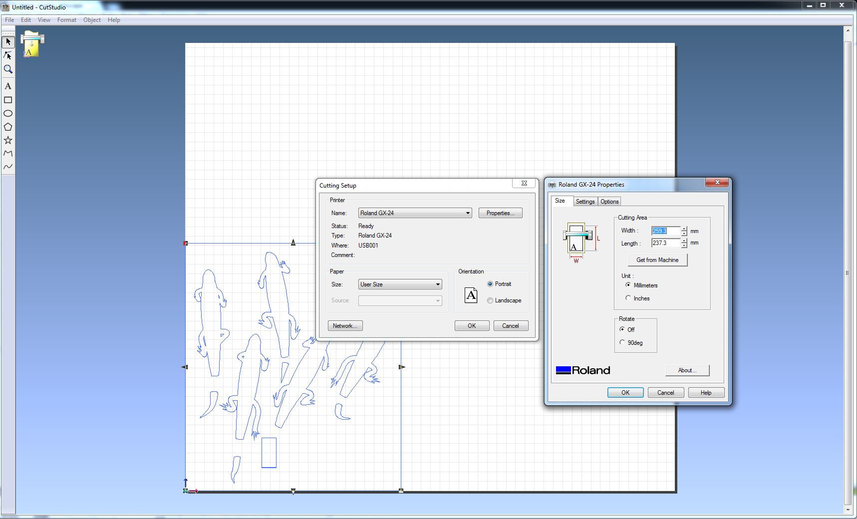
- Go to
File > Cutting properties > Propertieshere in Cutting Area you clickGet from machineand this is how you will get the proper format according to th size of your vinyl piece. Click ok. File > Cutting
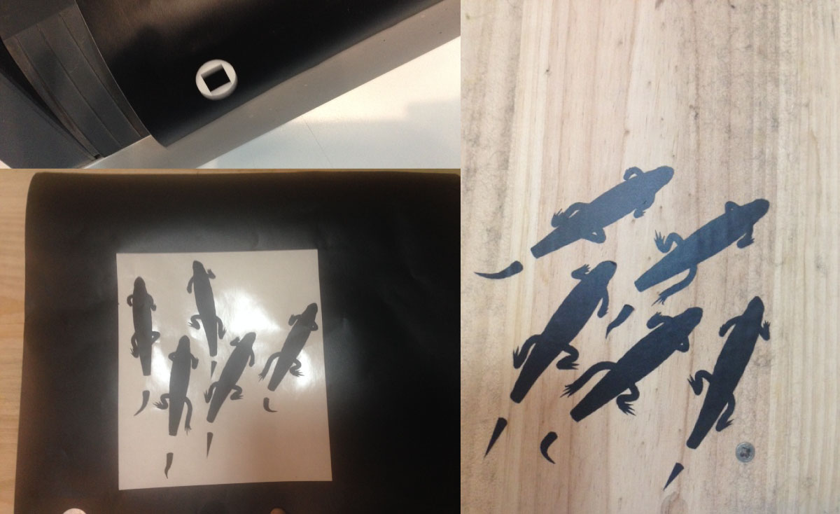
Success! Here photos of the test-cut and my lizards stickers.
Tipps and additional infos:
Inkscape have a plug-in
living hinge creator extension for foldable 2D: https://inkscape.org/en/~drphonon/%E2%98%85living-hinge-creatorMaker casefor making boxes: http://www.makercase.com/Fusion 360 slicer- for slicing 3D models and putting on the flat surfacethere are different profiles and ways of assambling the parts
- for profiles better to cut a hole which is rounded at the “entrance”
Files made during this assignment:
material template / ai
material template / dxf
pressfit / fusion
pressfit / dxf
pressfit / ai
pressfit / stl