11. Input devices
Group assignment
The detailed works of our group assignment are shown here.
Individual assignment
The goal of the individual assignment on this week was “measure something: add a sensor to a microcontroller board that you have designed and read it”
Plan for my final project
I decided to make the individual assignment as a part of my fianl project. As I described in WEEK3, I wil use HC-SR4 to detect distance around the mobile robot. In my plan, the mobile robot will have 4 HC-SR4 sensors to measure four directions around the robot. However, when I use only one microcontroller to control four sensors, there would be some issues.
One is time delation for property process in the sensors. Second is that there is not enough pin on the microcontrollers to connect four distance sensors and some actuators. So I planned a system architecture shown below figure.
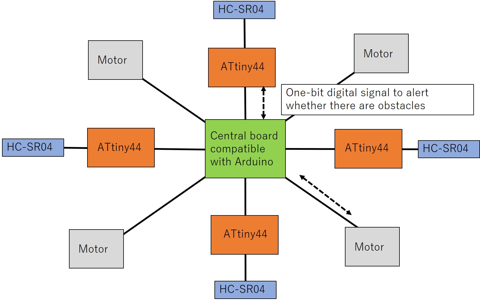
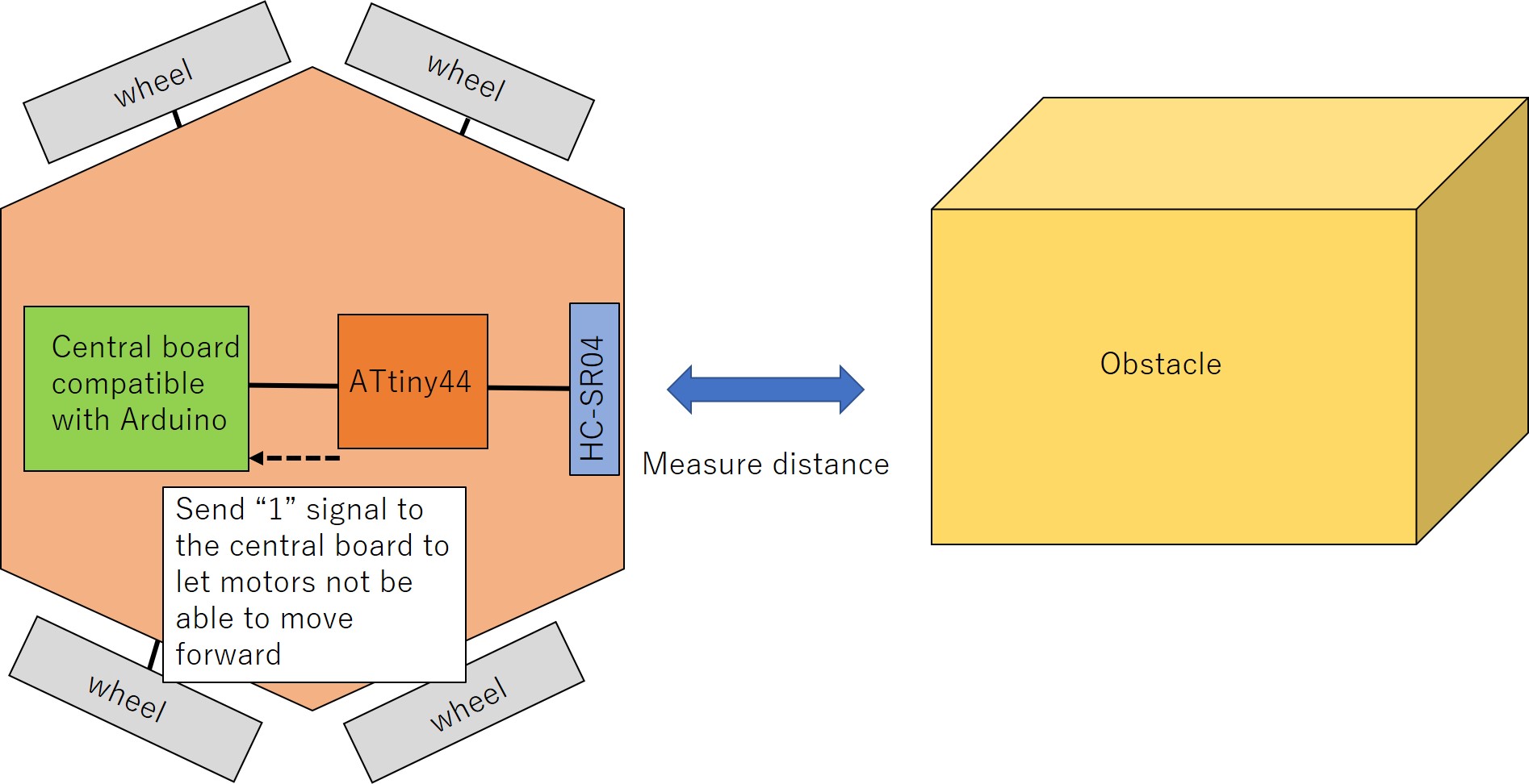
From the figure, each HC-SR4 will be controlled by each microcontroller (ATtiny 44) separately. Each microcontroller will be connected to a central controller (as similar as Arduino board ) and send a one-bit digital signal to the central board.
The purpose of sending a one-bit digital signal to the central board is to let the central board know which direction there is an obstacle near the mobile robot. According to the information, the central board will decide to stop or continue controlling motors.
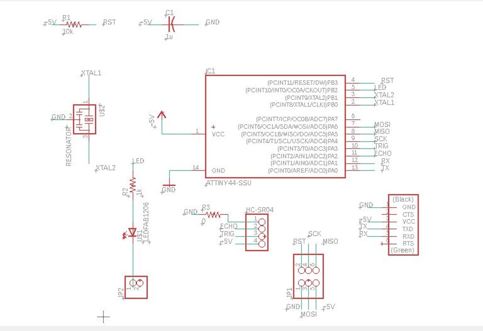
Designing an electrical board
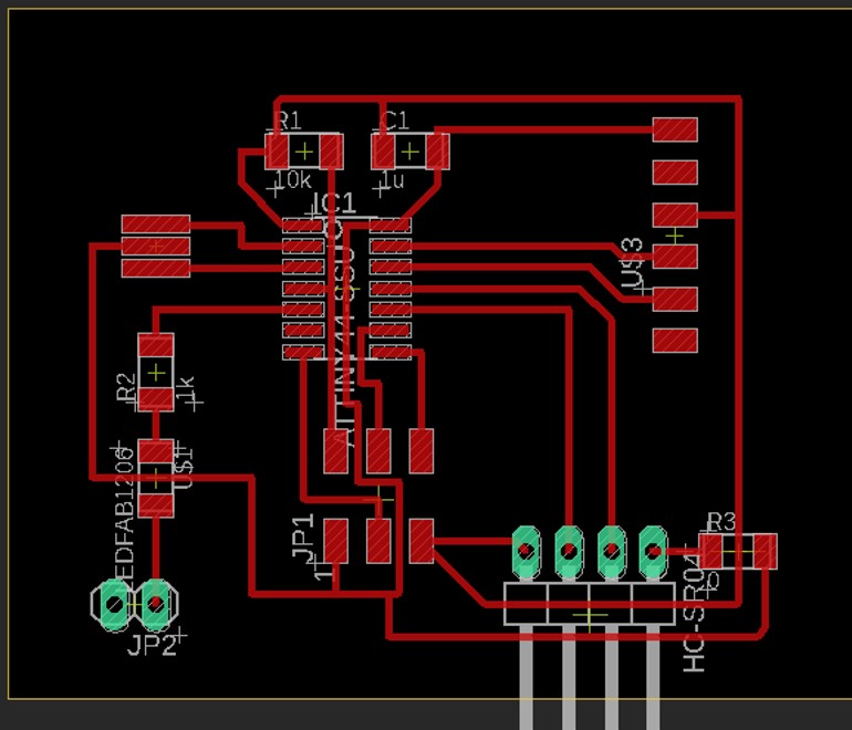
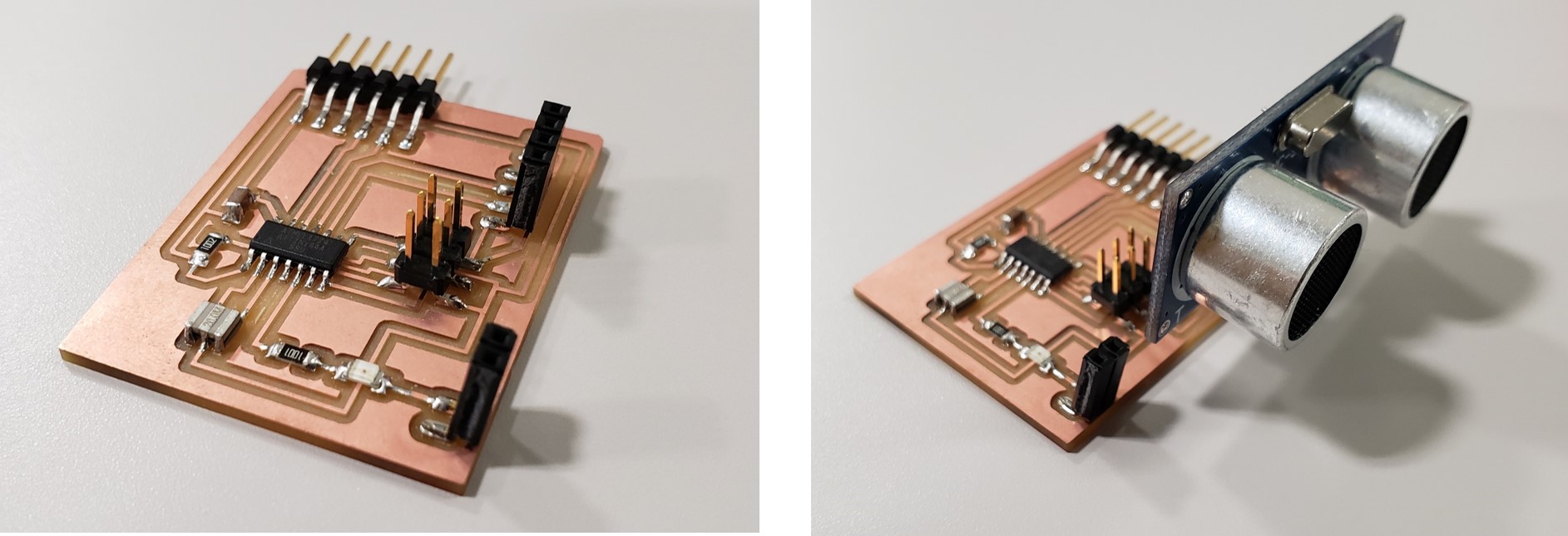
From the result of thinking about the system architecture of my final project, I designed one electrical board to control one HC-SR4 sensor. The basic structure of components was similar to the example one suggested in the lecture page on week11.
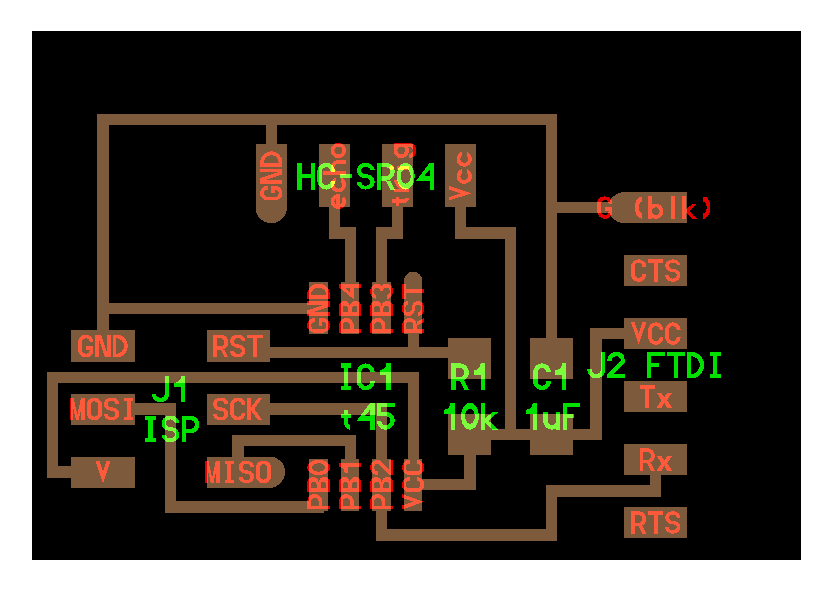
Showing measured distances on a serial communication display
For now, my plan for the assignment this week was to display the results of measured distances. To achieve that, I would combine serial communication and measuring distance function. Then, at first, I wrote down my code like below and used the similar make file suggested in the lecture page week 11.
The code of main function is below.
int main(void) {
   //
   // main
   //
   static char chr;
   static char buffer[max_buffer] = {0};
   static int index;

   unsigned char high;
   unsigned char low;
   unsigned long  counter;
   unsigned long filt;
   unsigned int distance;
   float eps=0.1;
   //
   // set clock divider to /1
   //
   CLKPR = (1 << CLKPCE);
   CLKPR = (0 << CLKPS3) | (0 << CLKPS2) | (0 << CLKPS1) | (0 << CLKPS0);

   clear(trigger_port,trigger_pin);
   output(trigger_direction,trigger_pin);
   clear(led_port,led_pin_out);
   output(led_direction,led_pin_out);
   //
   // initialize output pins
   //
   set(serial_port, serial_pin_out);
   output(serial_direction, serial_pin_out);

  TCCR0B |= (1 << CS01); // prescale /8
   //
   // main loop
   //
   index = 0;
   while (1) {
     //
     // trigger pulse
     //
     set(trigger_port,trigger_pin);
     _delay_us(10);
     clear(trigger_port,trigger_pin);
     //
     // wait for echo rising edge
     //
     // wait for echo rising edge
     //
     high = 0;
     TCNT0 = 0;
     TIFR0 |= (1 << TOV0);
     while (1) {
        if ((echo_pins & echo_pin) != 0) // check for rising edge
           break;
        //If there is a timeout break the while. I need to send a new echo
        if ((TIFR0 & (1 << TOV0)) != 0) { // check for counter overflow
           high += 1;
           if (high == timeout)
              break;
           TIFR0 |= (1 << TOV0);
           }
        }
      //
      // rising edge found, wait for falling edge
      //
      high = 0;
      TCNT0 = 0;
      TIFR0 |= (1 << TOV0);
      while (1) {
         if ((echo_pins & echo_pin) == 0) { // check for falling edge
            low = TCNT0;
            break;
            }
         if ((TIFR0 & (1 << TOV0)) != 0) { // check for counter overflow
            high += 1;
            if (high == timeout)
               break;
            TIFR0 |= (1 << TOV0);
            }
         }
         if (high == timeout && low == 0){
            put_string(&serial_port, serial_pin_out, "Object out of range");
            put_char(&serial_port, serial_pin_out, 10);
            _delay_ms(1000);
            continue; //The main loop, do not show anything

         }

         char high_char[5];
         put_string(&serial_port, serial_pin_out, "High:");
         itoa(high, high_char, 10);
         put_string(&serial_port, serial_pin_out, high_char);
         put_string(&serial_port, serial_pin_out, " Low:");
         char low_char[5];
         itoa(low, low_char, 10);
         put_string(&serial_port, serial_pin_out, low_char);
         counter = 256*high + low;

         distance = counter*8/1160;
         //filt = (1-eps)*filt+eps*counter;

         char counter_char[8];
         put_string(&serial_port, serial_pin_out, " Counter:");
         itoa(counter, counter_char, 10);
         put_string(&serial_port, serial_pin_out, counter_char);
      put_string(&serial_port, serial_pin_out, " Distance:");
      char distance_char[5];
         // convert distance to string [buf]
      itoa(distance, distance_char, 10);
      put_string(&serial_port, serial_pin_out, distance_char);
      put_string(&serial_port, serial_pin_out, " cm");
         put_char(&serial_port, serial_pin_out, 10);

         //_delay_ms(10);
         _delay_ms(1000);

      }
   }
After compiling the code, I opened the serial communication display to check the measured distances by using term.py.
However, the display showed garbled texts.
“bad result”
What happened? To verify the causes, I checked first whether serial communication could work correctly on the electrical board by using hello.ftdi.44.echo.c and hello.ftdi.44.echo.c.make.
Trying basic serial communication was successful. Then, serial communication could also work on this board. I checked what was differences between these files. I found the values of “F_CPU” were different. In hello.ftdi.44.echo.c.make, F_CPU=20000000. On the other hand, in the sample make file, F_CPU = 8000000. Then when I changed the F_CPU value from 8000000 to 20000000. Serial communication was successful as shown below.
“result”
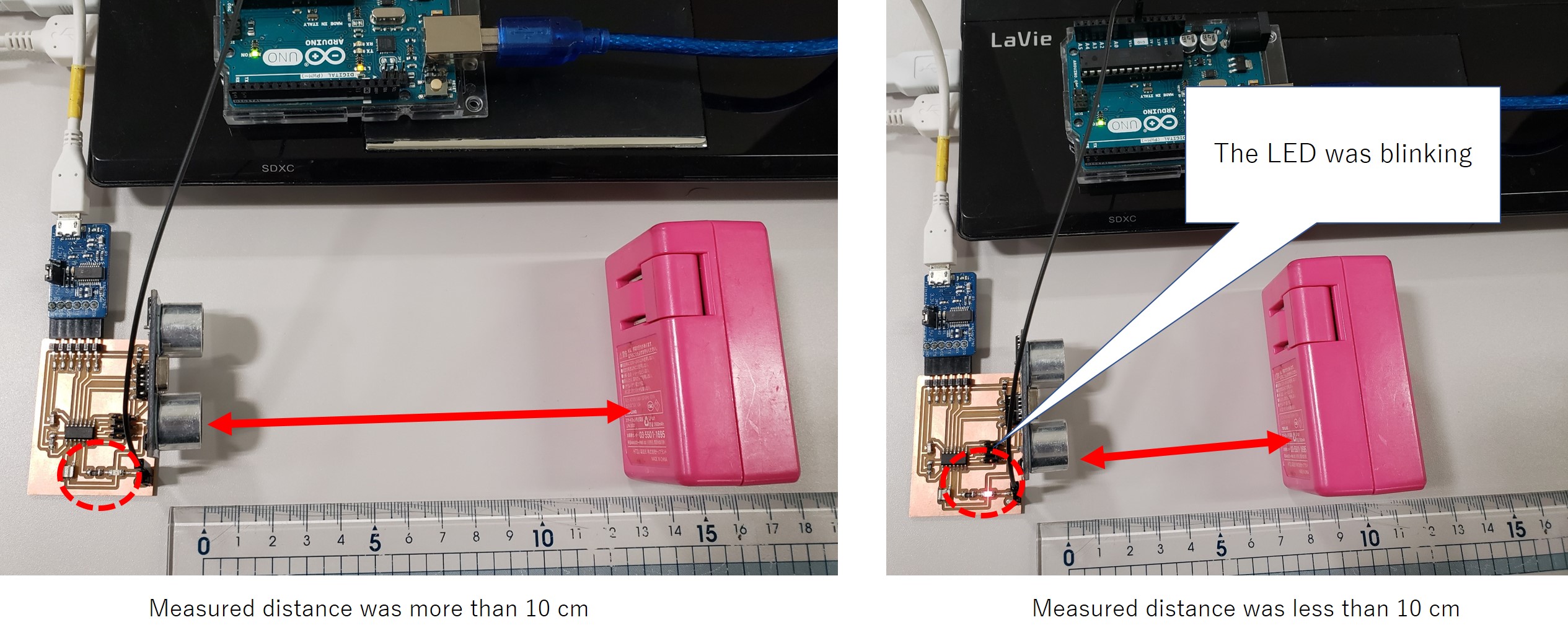
Blinking a LED based on the results of measured distances
To achieve one of the required functions for my final project as described above, a microcontroller should send 0 or 1 digital signal to the central microcontroller. On this week, I add a LED to check whether a digital signal is absolutely sent to the central controller.
In my case, the threshold distance was defined as 10 cm. Then, when measured distances were less than 10 cm, ATtiny 44 will send “1” signal and the LED will blink.
I added the below code in my main function.
       if (distance<=threshold){
           led_port=0b0100;
           _delay_ms(5);
           put_string(&serial_port, serial_pin_out, "OOOPS!");
         }
         else{
           led_port=0b0000;
           _delay_ms(5);
           put_string(&serial_port, serial_pin_out, "SAFE");
         }
Download link
Eagle files
Png files
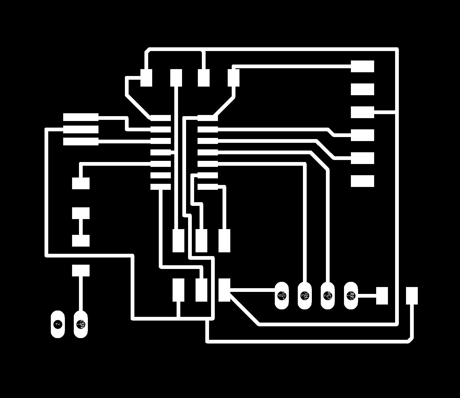
Codes
- Showing measured distance
- Blinking a LED based on the measured distances
- Makefile
Note: For both cases, the contents of makefile are the same.