Skip to content

5. Electronics & Programming

A. System Description

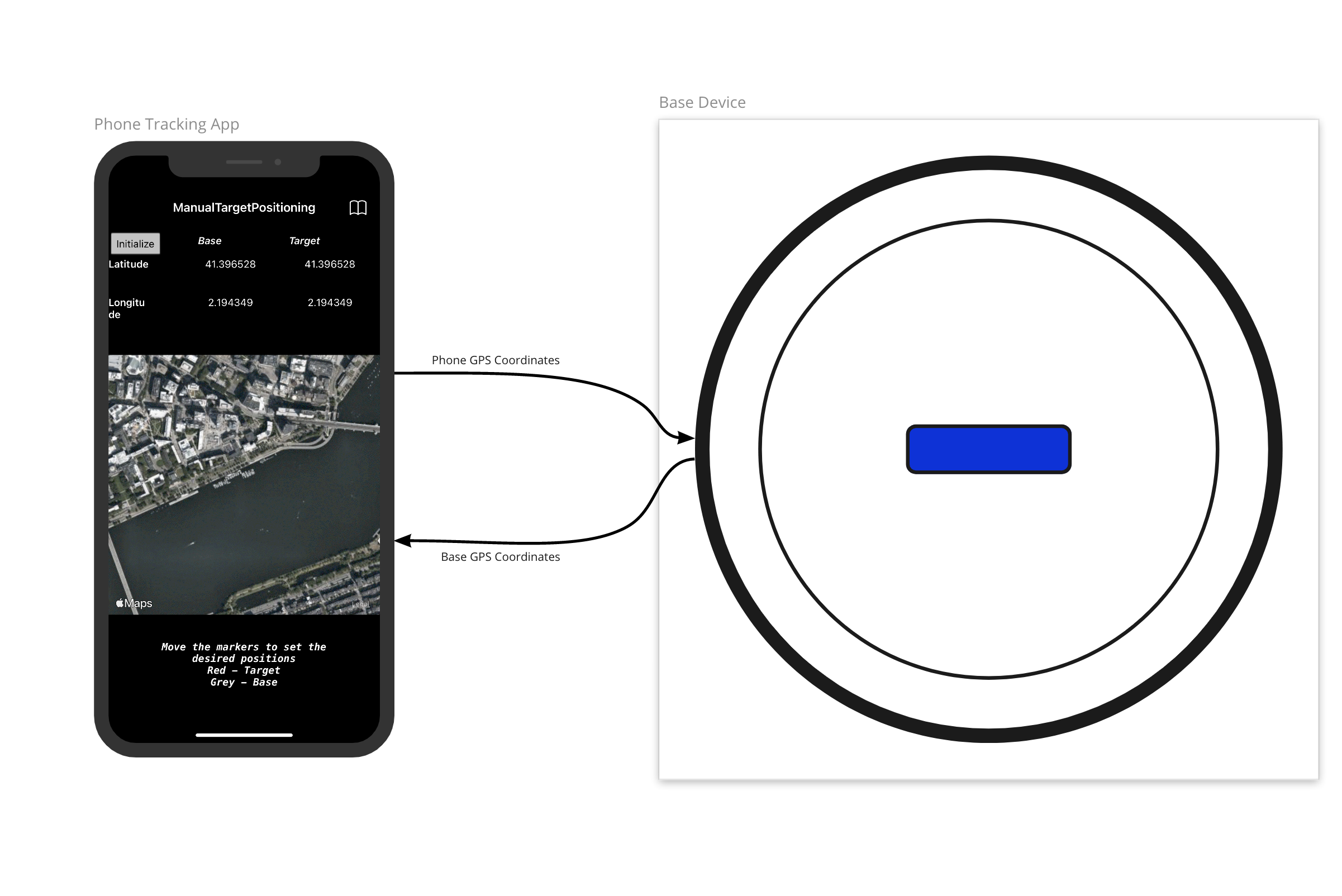
The end-goal was to create a system which tracks a moving object through changes in its GPS coordinates.

System Structure


Structure Diagram

System Structure Diagram


I/O Diagrams

As detailed in chapter 2 Project Management, the vision for the project was divided into 5 phases. For the academy, I focused on completing the first phase, and perhaps the second if I had enough time. This wasn’t the case as I encountered a couple mechanical and technical issues which slowed down my progress.


Phase 1

Phase 1 focused on designing a base technology on which the rest of the system’s features could be developed. I viewed this as a modular pan only system which can be controlled manually. The base system features a GPS, a compass, a stepper motor, and an ESP32 hosting a WiFi network. Furthermore, a phone app issues manual user commands to the base device through the WiFi network. The below diagram describes the role each of these components in this particular phase.
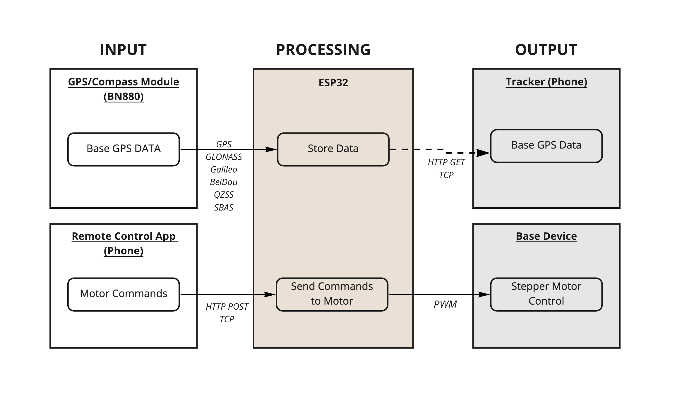

I/O Diagram P1

Phase 1 I/O Diagram


In this first phase, the companion app is used to send commands to the system over WiFi. When the ESP32 received a command, It moves the motor in the instructed direction. In addition, the GPS module’s readings are used to simply display the base device’s coordinates to the user on the phone app. The functionalities in this phase were kept to the bare minimum as I had anticipated I would have issues with the panning mechanism itself. This simplicity would allow me to assess the system as a mechanical device first, which I viewed as essential to optimise in order to create a reliable development platform.


Phase 2

The second phase would start including and combining GPS and Magnetometer readings to provide the base tracking feature. The GPS coordinates of the base would be compared to those of the user’s tracker (phone), yielding a target heading. The device’s magnetometer, installed in a manner that allows for the camera’s orientation to be measured, would be used to compare the device’s current heading to the target heading in order to determine in what direction and by what distance the motor should be moved to align the camera with the target.
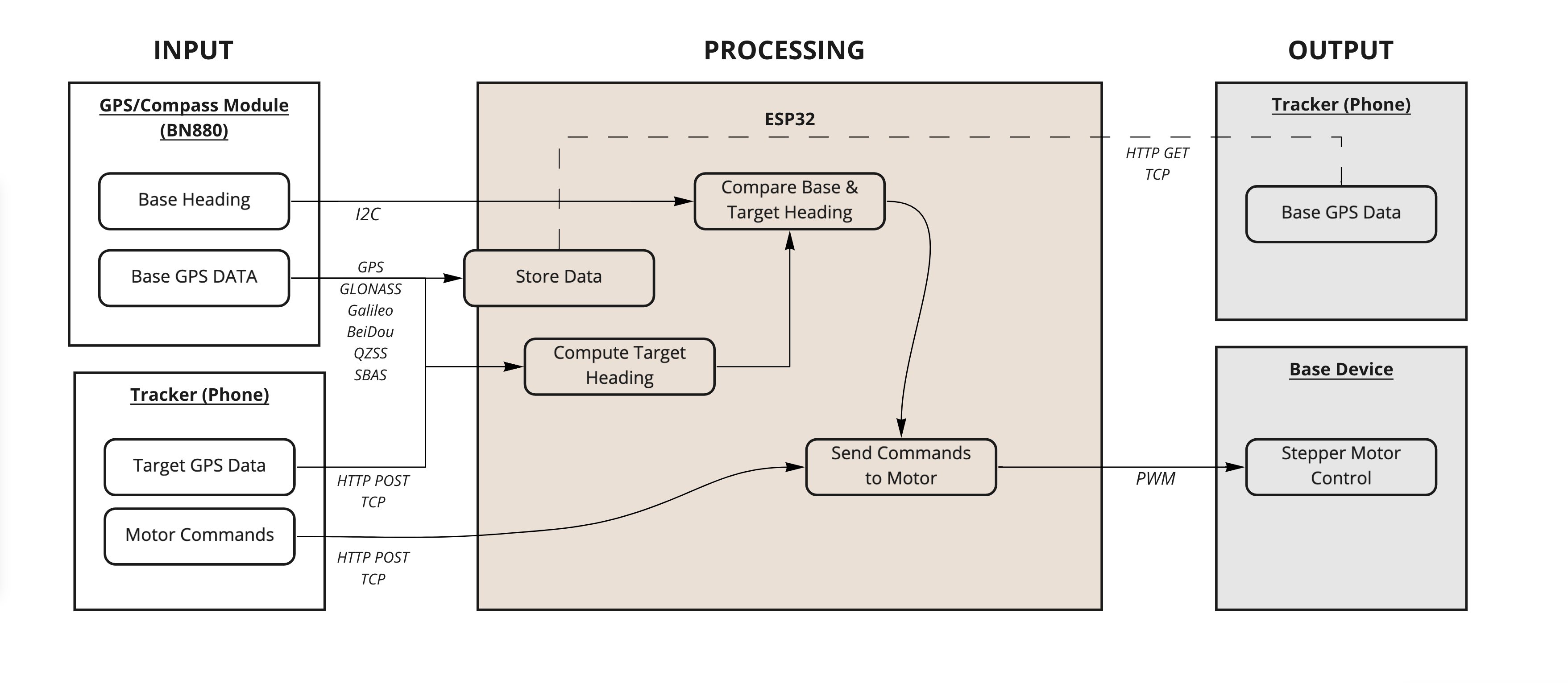

I/O Diagram P2

Phase 2 I/O Diagram


B. Electronics Design

I decided to have two separate boards. One would contain the micro controller and connections to all I/O components. The other would act as the interface for programming, serial communication and power input. Both were to be connected with jumper cables. All boards were milled on an SRM-20 using a combination of 1/64 and 1/32 end-mills.

I/O Modules

BN880 - GPS/Compass Module

BN880

The work I carried out during the Input week details how to interface and work with Beitian’s BN880 module. The difference between that week’s board and the one to be developed for the final project is in the processor used. For the final project, I decided to use an ESP32 which, according to its datasheet (See section 2.3), can be supplied with up to 3.6V at more than 0.5A. For a single power source, the recommended power supply is of 3.3V.

This is an issue as the BN880 module requires a power supply of 5V. Furthermore, I couldn’t simply power the BN880 with 5V and directly connect it to ESP pins as I would have run the risk of damaging them, because the module’s output signals will have a 5V logic level. I therefore used a bi-directional logic level converter (LLC) produced by Sparkfun. The LLC converts signals originating from the bn880 from a 5v to a 3.3V logic level, and vice-versa for signals originating from the ESP and destined to the BN880.

LLC

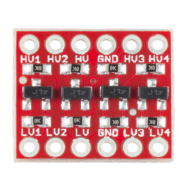
Logic Level Converter


Stepper Motor Control - TMC2208

nema14

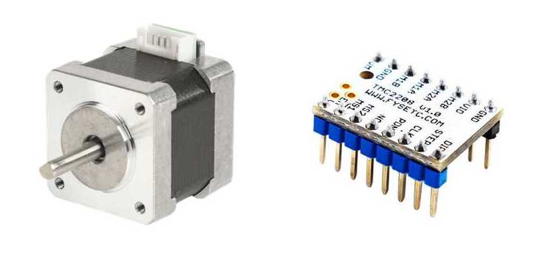
NEMA14 Stepper Motor (Left) & TMC2208 Driver (Right)

For the power train, I settled on Stepper motors as I had already gained some experience in using them for the machine design week and the output week. The stepper driver I used was the TMC2208 by FYSTEC, which used Trinamic’s TMC2208-LA chip. This driver is capable of up to 1/256 micro-steps and is stealthchop2 compatible. It was selected as drives stepper motors with little to noise emitted, allowing for a silent operation. This is essential for my project as I need to limit the noise emitted by the device to the strict minimum. Its implementation is explained in week12’s documentation page.

Interface Board

The interface board is used to connect to an FTDI interface for programming and serial communication through male headers, and to a power source through a power barrel jack. The power adapter used supplies a DC voltage of 12 Volts at up to 6 Ampers. For the copper boards used, the track width of the tracks connected to the power source had to be set to 2.0 mm in order to ensure a proper dissipation of the heat generated, and avoid having the tracks pop off and eventually break. This value was calculated using the tool on 4pcb.com.

interface schematic

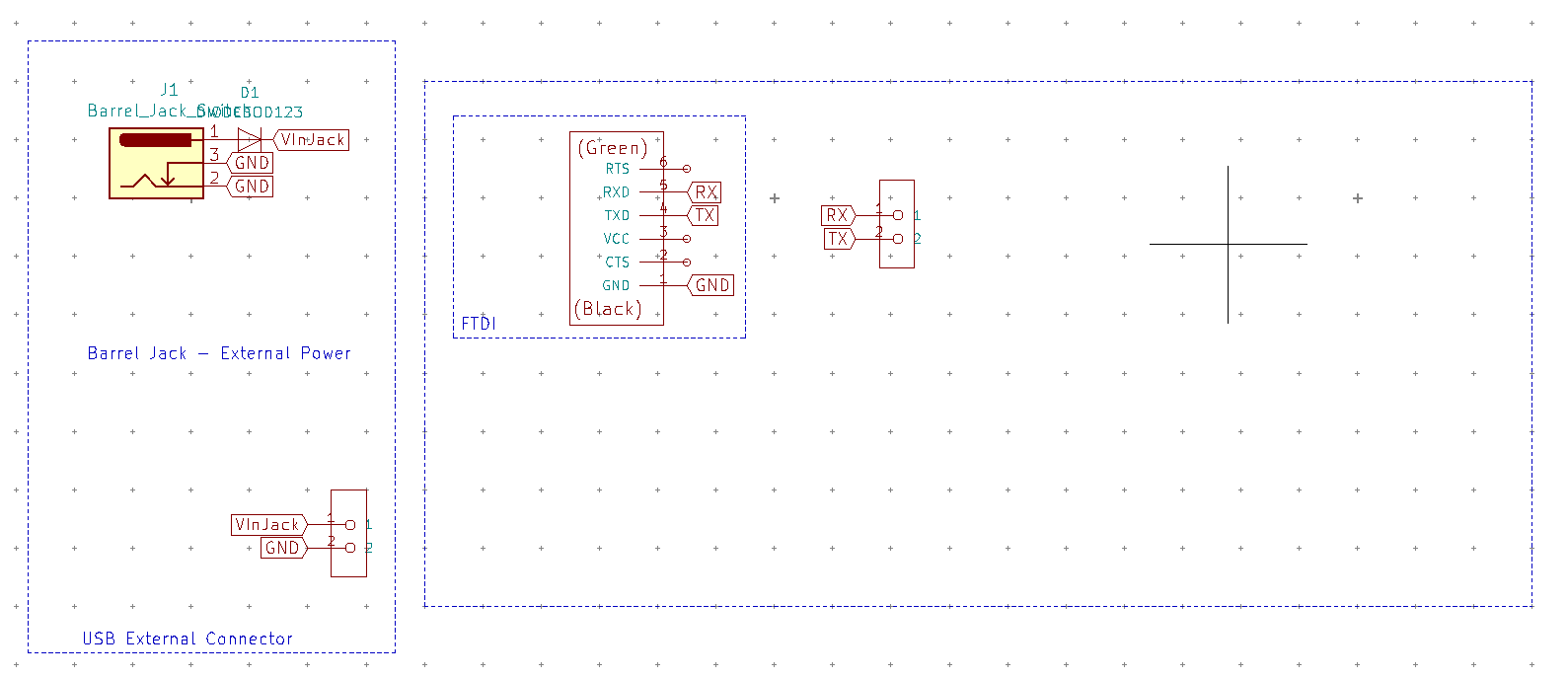
Interface Board Schematic

interface layout

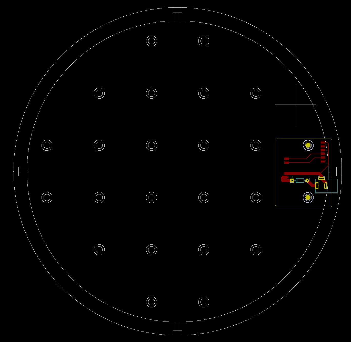
Interface Board Layout

interface layout

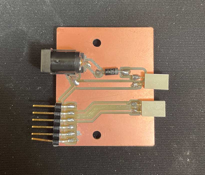
Soldered Interface Board

interface layout

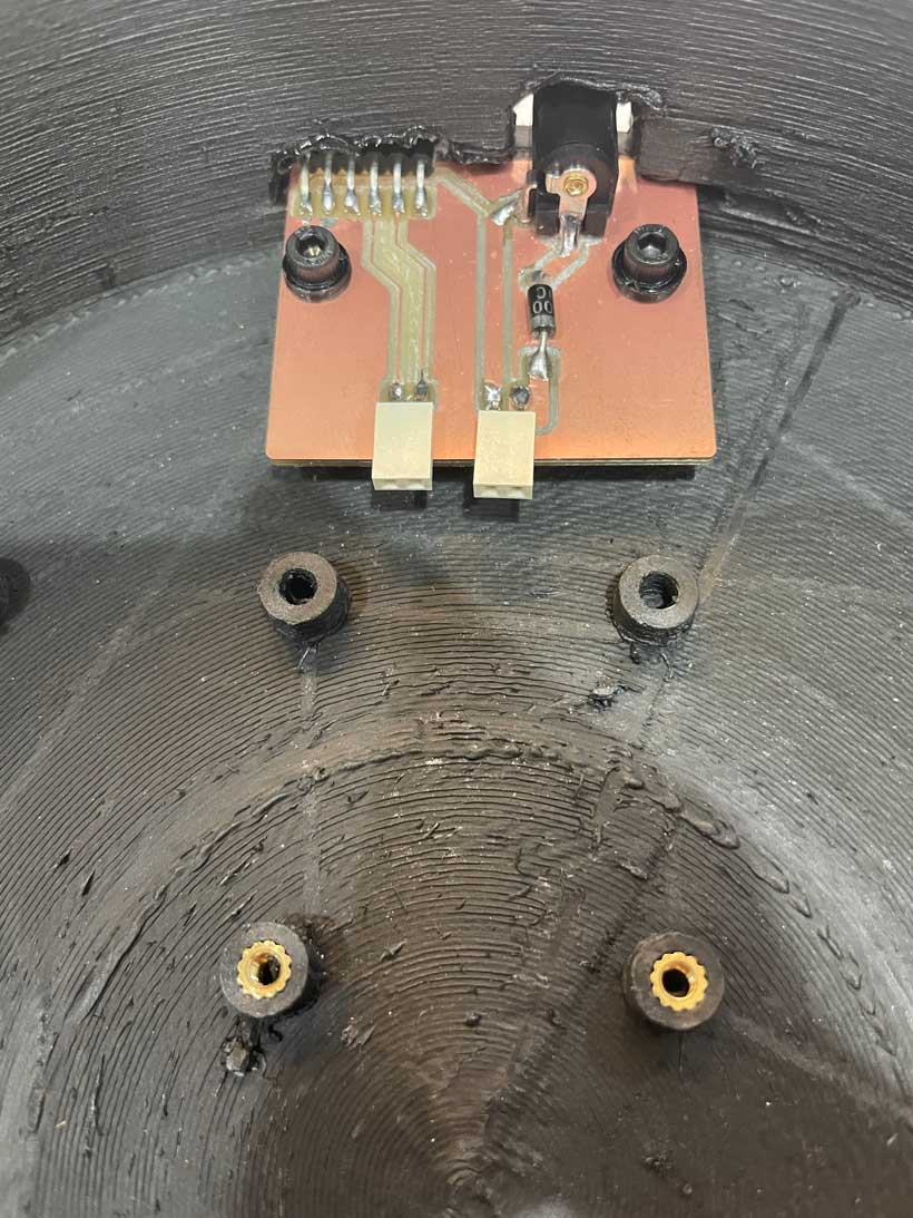
Picture of Interface Board installed On the Bottom Casing


Central Board

The central board would feature an ESP32 acting as the central control unit, a stepper motor driver and connectors for the GPS/Compass module and the stepper motor. The BN880 module requires 5V of power whereas the ESP32 cannot go above 3.3V. As such, I have used 2 voltage regulators converting the power received from the DC jack to 5V and 3.3V. Furtermore, because the BN880 is supplied with 5 volts, its output signals are also set to 5V, which might damage the ESP32 if connected directly. I therefore used a Logic Level converter which would convert the signals form received from the GPS/Compass module from 5V to 3.3V, and the signals sent by the ESP to the module from 3.3V to 5V.
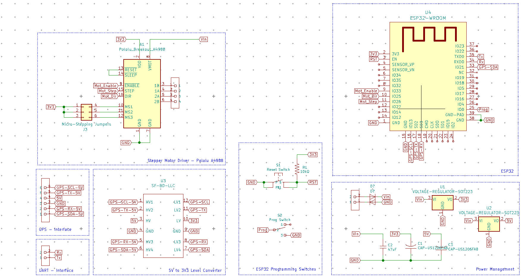
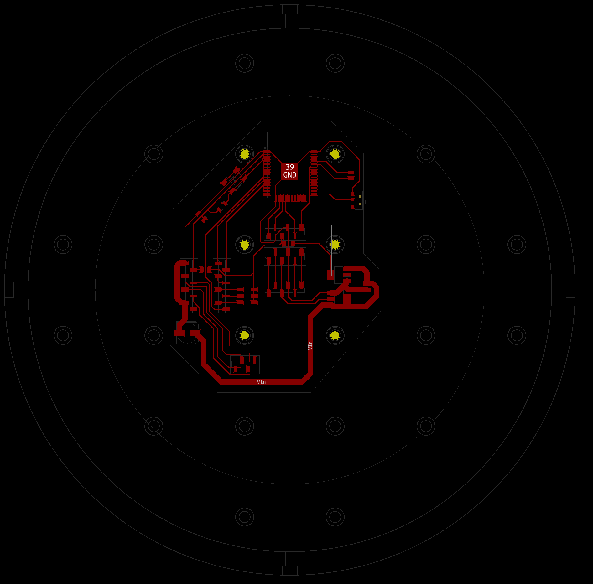

central_schematic

Central Board Schematics


I had initially tried to mill a double-sided circular board, on which all modifiable components (LLC & Driver) and connectors would be placed on one side, and all permanent components on the other. Both sides would be connected with vias. However, I wasn’t able to properly align both sides during the milling process, causing the tracks to be offset from the holes. I therefore moved to a simpler design as I was running out of time.

circular_top_layout

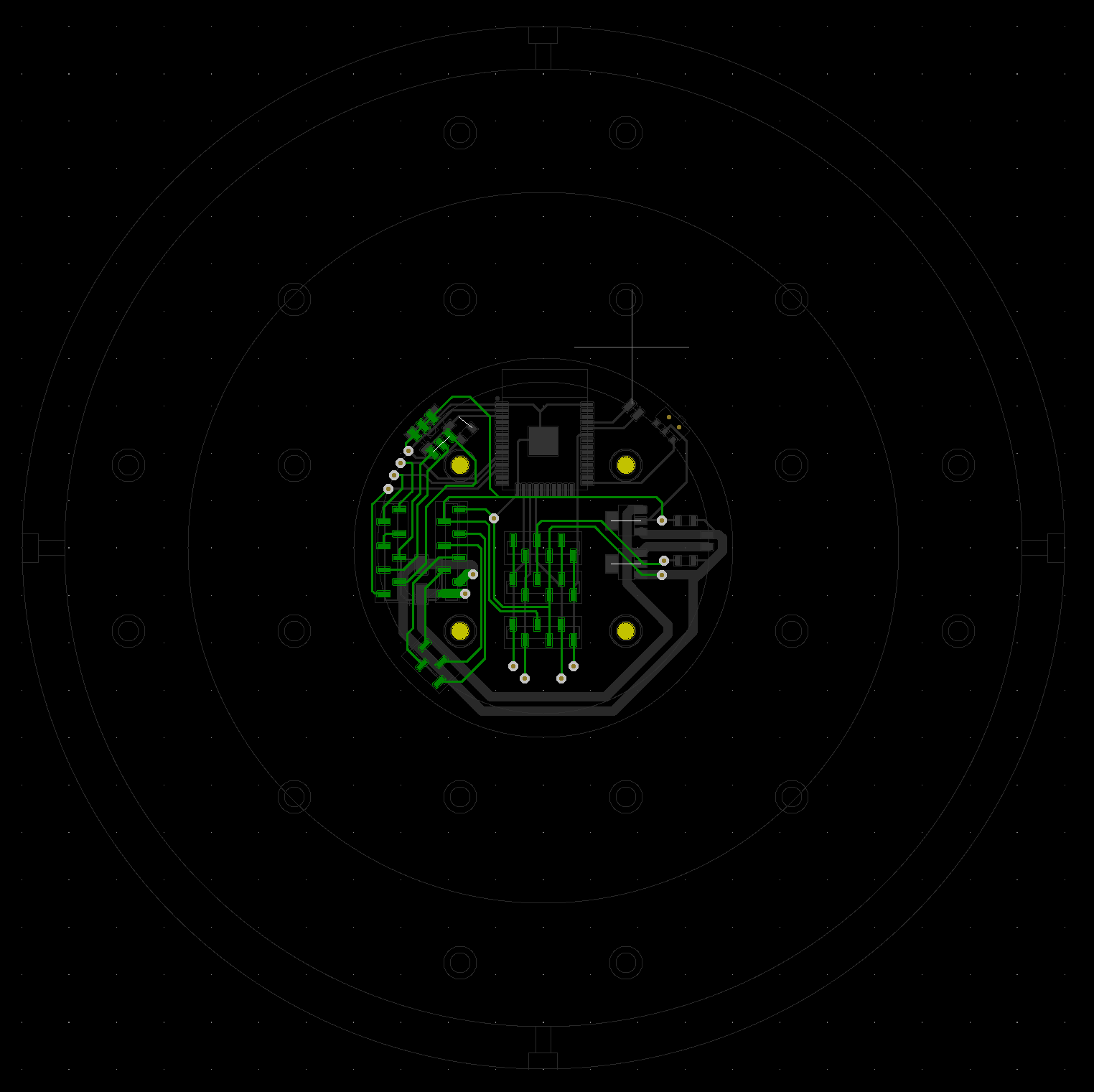
Top Layout of Circular Board
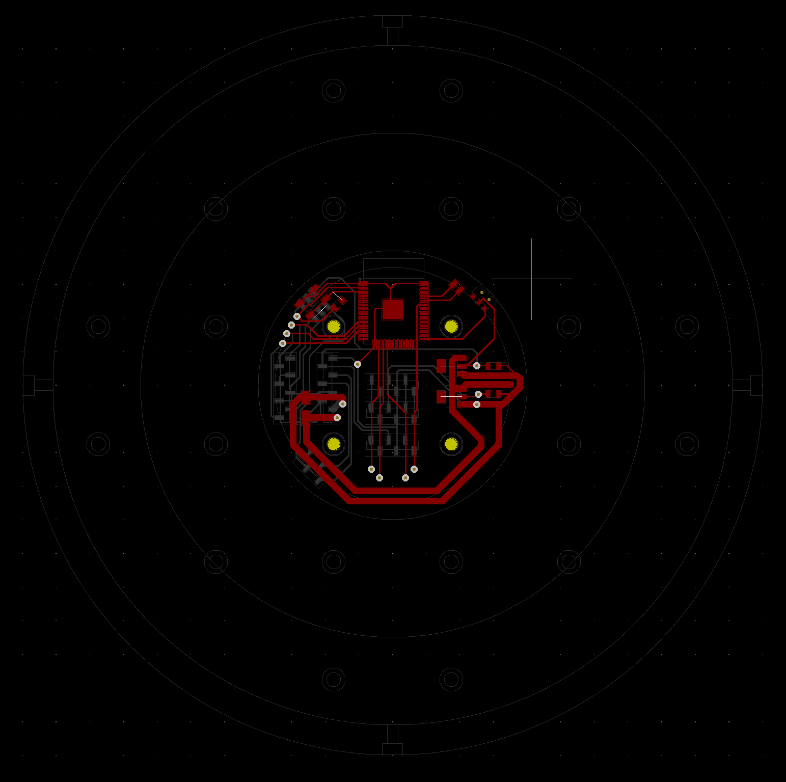
circular_top_layout

Bottom Layout of Circular Board


While less elegant, the one sided design would be much easier to produce. However I had made a mistake while desiging it by forgetting to ad a 2.0 mm wide track from the ground source to the motor driver, causing some 0.4 mm ground tracks to break and forcing me to use jumper wires on the board. Nevertheless, the board was functional in its frankenstein state. I still updated the layout, but wasn’t able to mill a new one in time.

central_layout_faulty

Faulty Layout of Central Board

central_milled_faulty

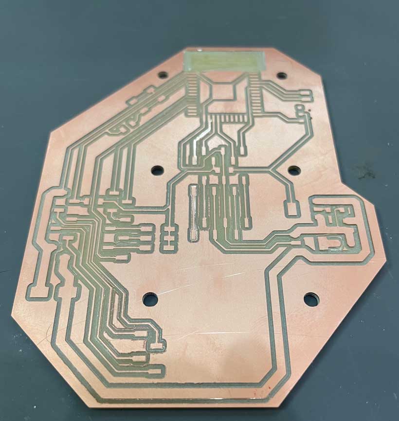
Milled Faulty Central Board

frank_faulty

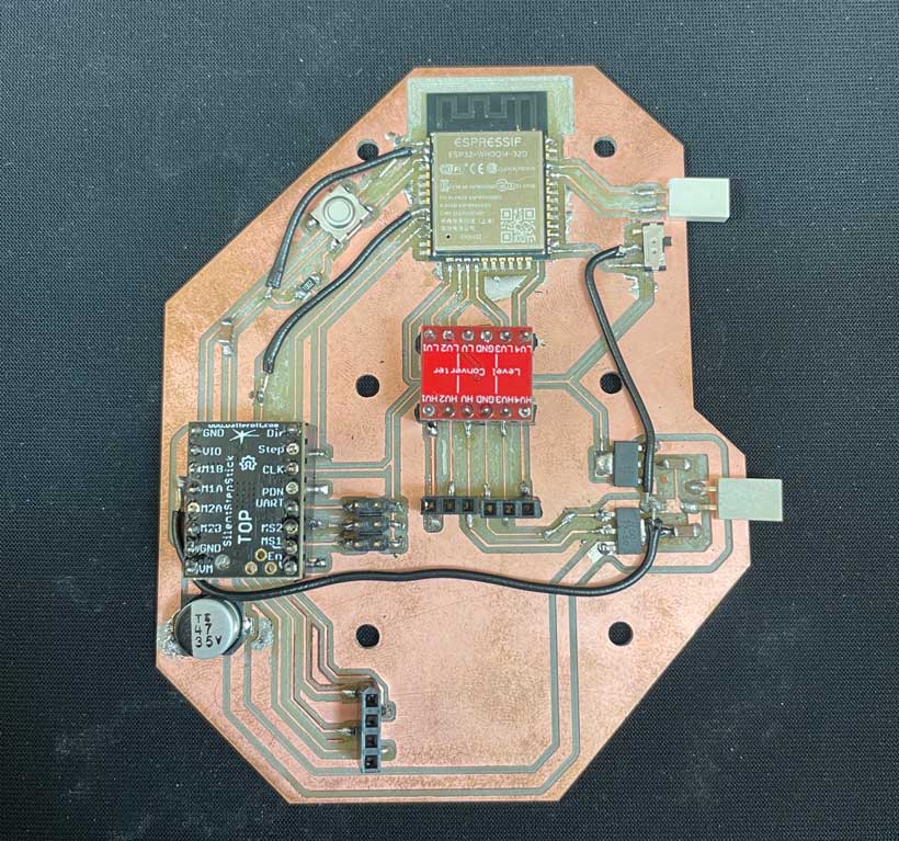
Assembled Faulty Central Board
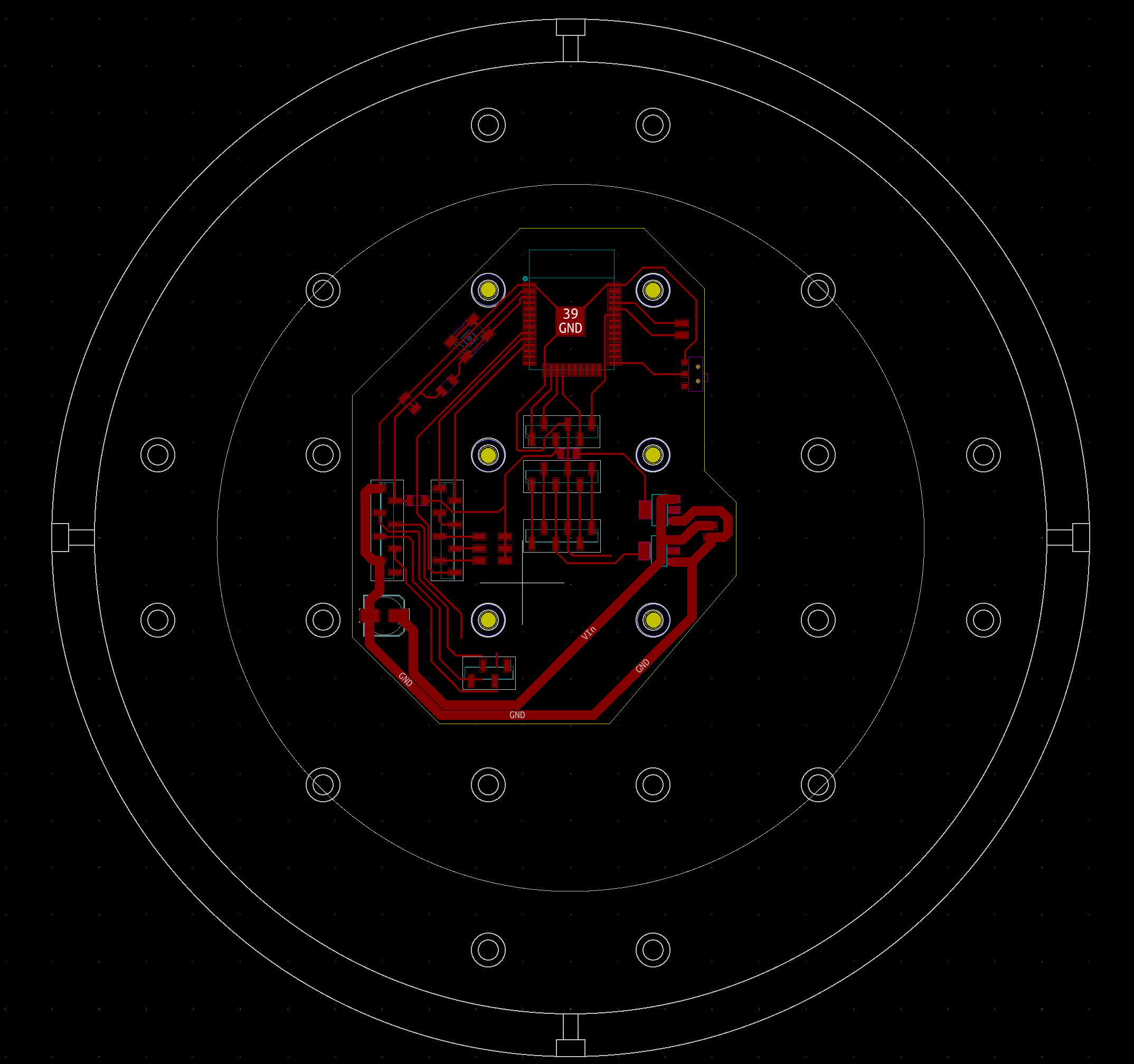
central_layout_faulty

Corrected Layout of Central Board


And here are the boards installed on the bottom casing.
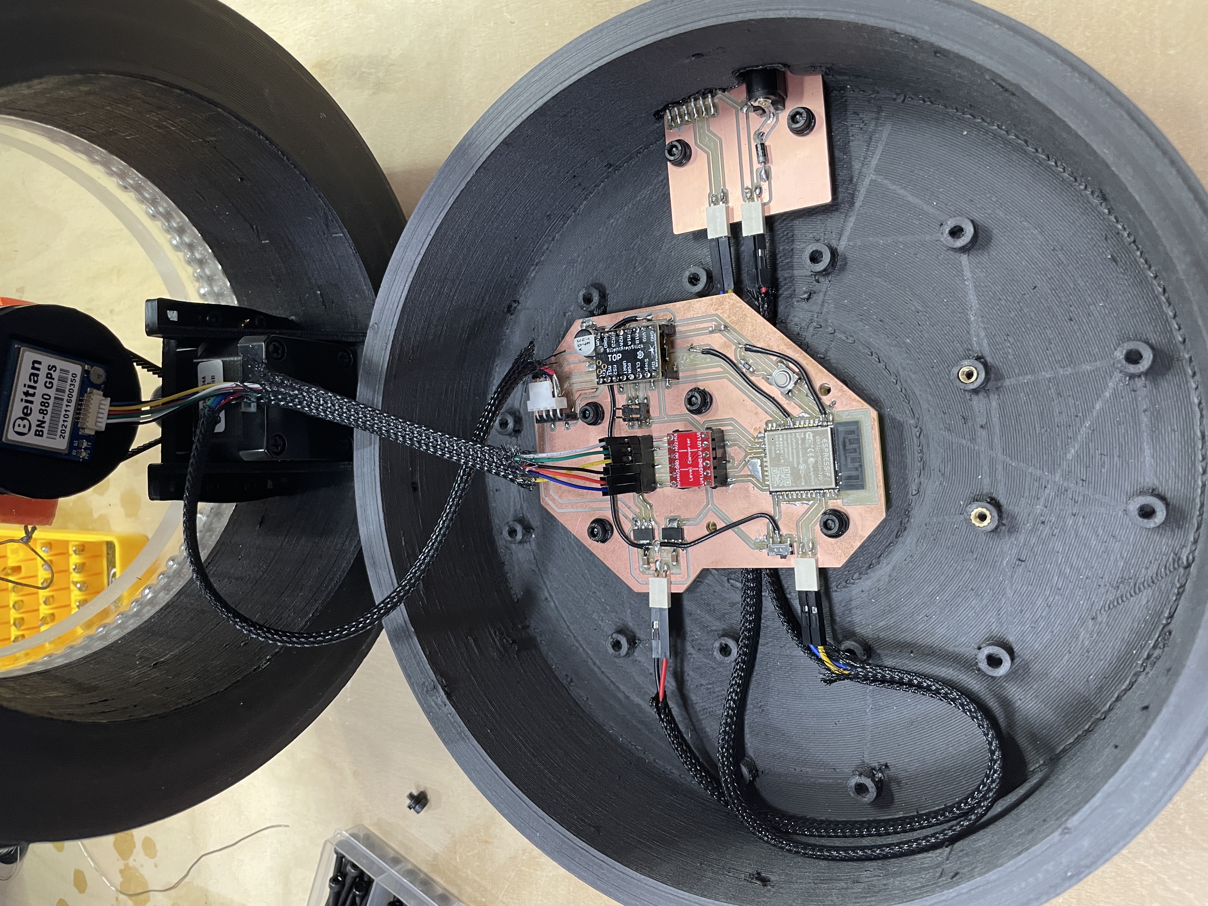
installed boards

Installed Boards

C. The Companion Phone App

The companion app was developed on the MIT app inventor. The app inventor is made up of two development modules.

Interface Design

App interfaces are designed in the “Designer” module. Here, layout and desired functional elements can be added and positioned where desired.


mii_app_interface

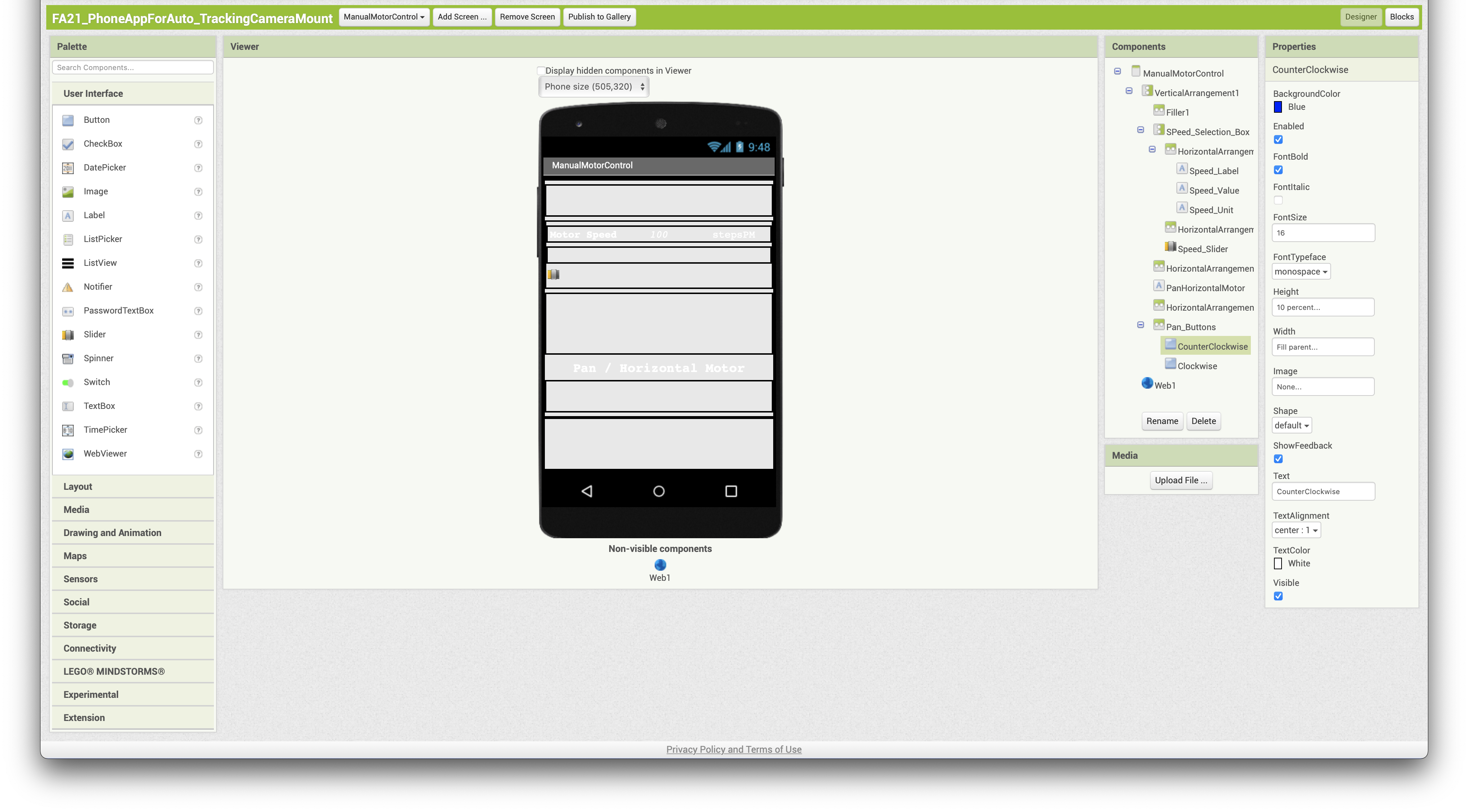
Phone App - MIT AppInventor Designer Module screenshot


Phase 1’s app interface was composed of three components:

  1. A slider used to define the speed at which the motor was to move.
  2. A button to turn the motor in a clockwise direction.
  3. A button to turn the motor in a counter-clockwise direction.

The selected motor speed would be displayed to the user above the slider. Below is the resulting app interface.


app_interface

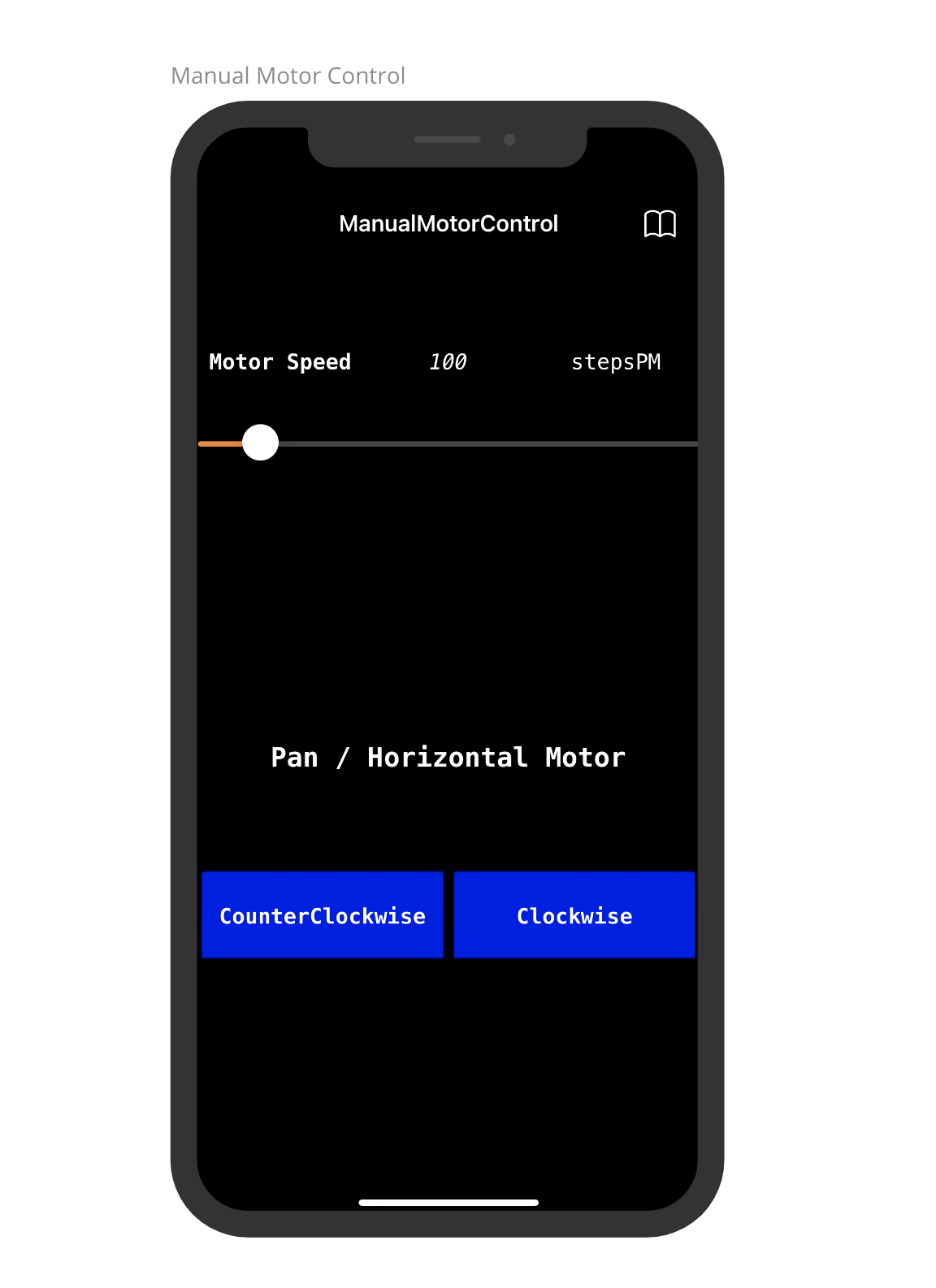
Phone App - Manual Motor Control Interface


App Programming

Programming an app designed on the MIT app inventor is achieved through its “Blocks” module where block based coding of interface elements is used to define the app’s functionality.


app_blocks

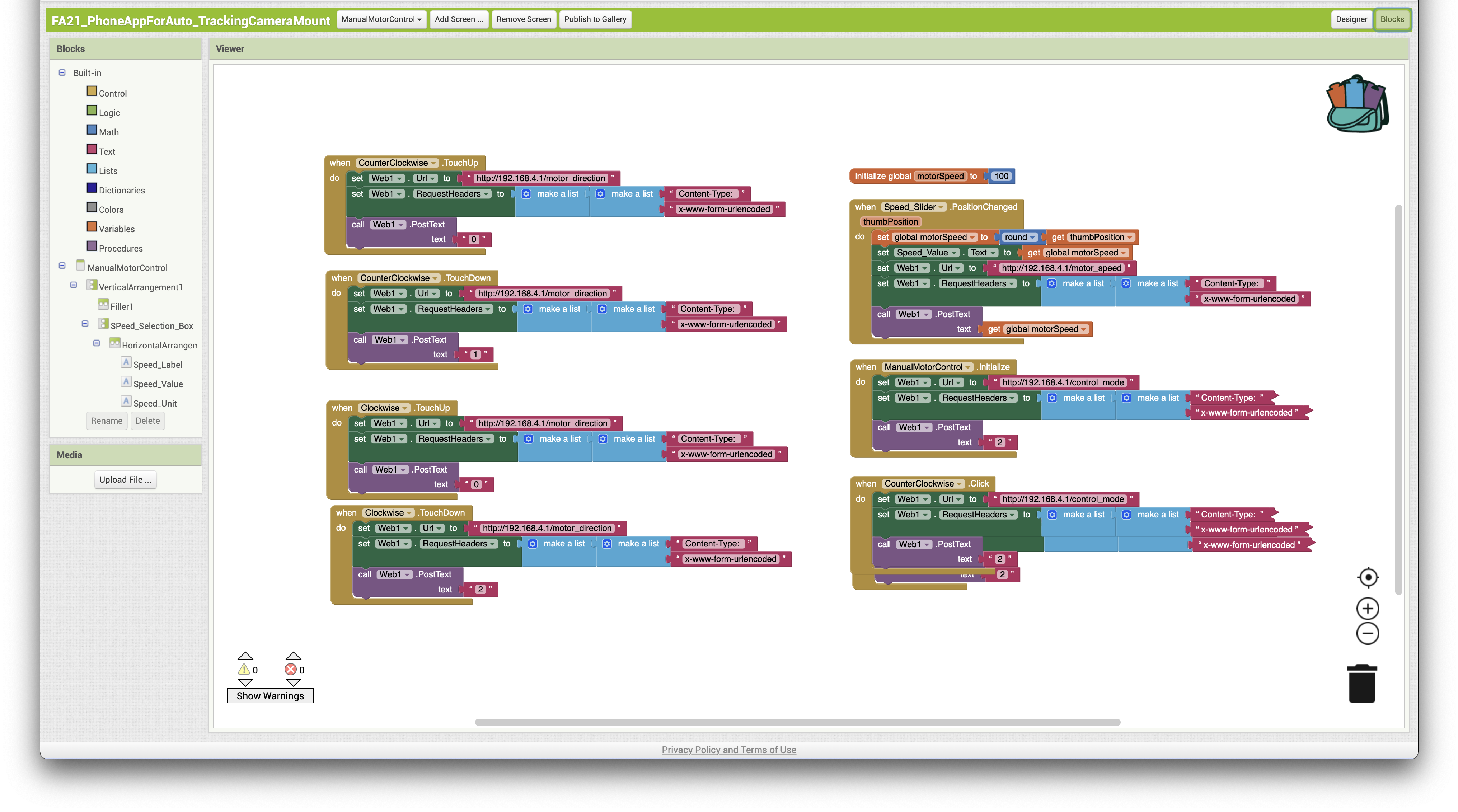
Phone app - MIT App Inventor Block Programming


The app’s code basically follows the logic of the below flow chart. In short, when the user interacts with either buttons, a value (0, 1 or 2) is sent to an address of the HTML server (http://192.168.4.1/motor_direction) hosted by the base device’s ESP32. Values 1 (Counter-Clockwise) and 2 (clockwise) are sent while one of the buttons is pressed, once at each tick. When the user interacts with the slider, the set speed value is sent to another address of the server (http://192.168.4.1/motor_speed).
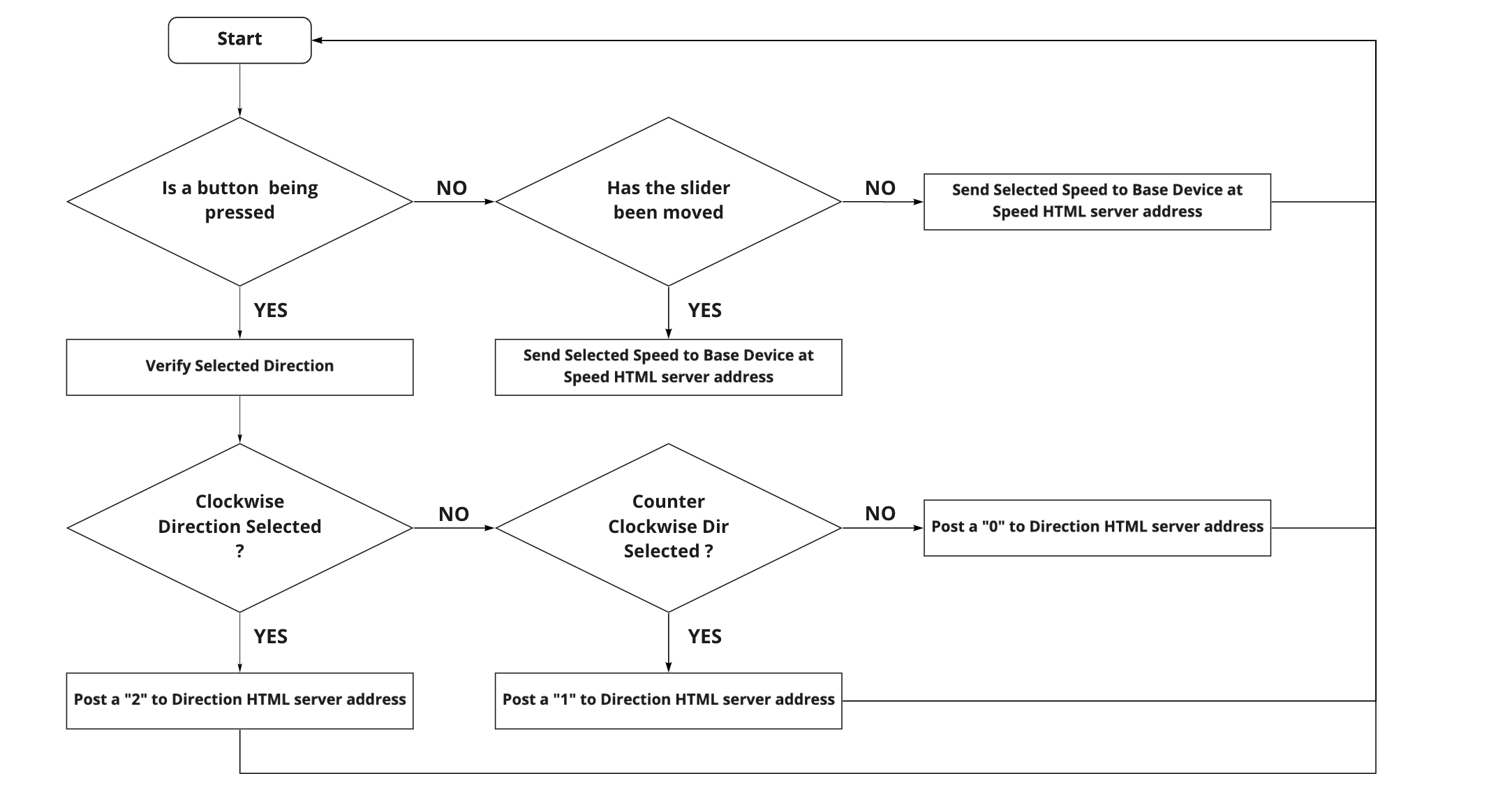

app_flowchart

Phone app - Program flow chart


The transfer of data from the phone to the board, and vice-versa, is achieved by means of HTML POSTs. An encoded string message is placed at a given HTML address, replacing anything that was there previously.

I’ve spent a considerable amount of time determining how to properly encode the posted data. The arduino program I had written was receiving the data but was unable to decipher it. This was because POST requests are submitted via HTML forms where the type of encoding (or MIME type = media type) needs to be specified (Reference), which I hadn’t done in my previous attempts. This was achieved by adding a ‘content-type’ attribute to the header of the request. In this case, the content type was set to the default “x-www-form-urlencoded”.


app_flowchart

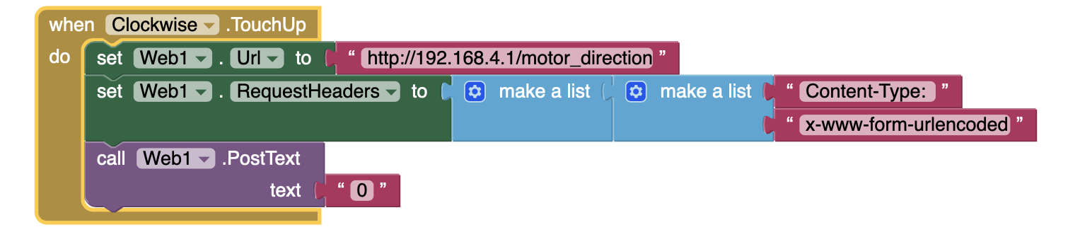
HTML Post Request Structure on the MIT AppInventor


D. Base Device Programming

The device’s program was developed in Arduino C using the arduino IDE. I used a total of 3 libraries in order to obtain the functionalities I was looking for.


Library Function
WiFi.h Hosting a WiFi Network from an ESP32
ESPAsyncWebServer.h Hosting an Asynchronous Web server on an ESP32
AccelStepper.h Position and Speed based control of stepper motor


The program has been developed to account for the implementation of future phases. It allows for the user to switch between modes defined as “Auto-Tracking” (GPS based tracking - Phase 2), “Manual Control” (Phase 1) and Manual Positioning (Testing platform for the transition from phase 1 to phase 2). It follows the logic of the flow chart shown below.
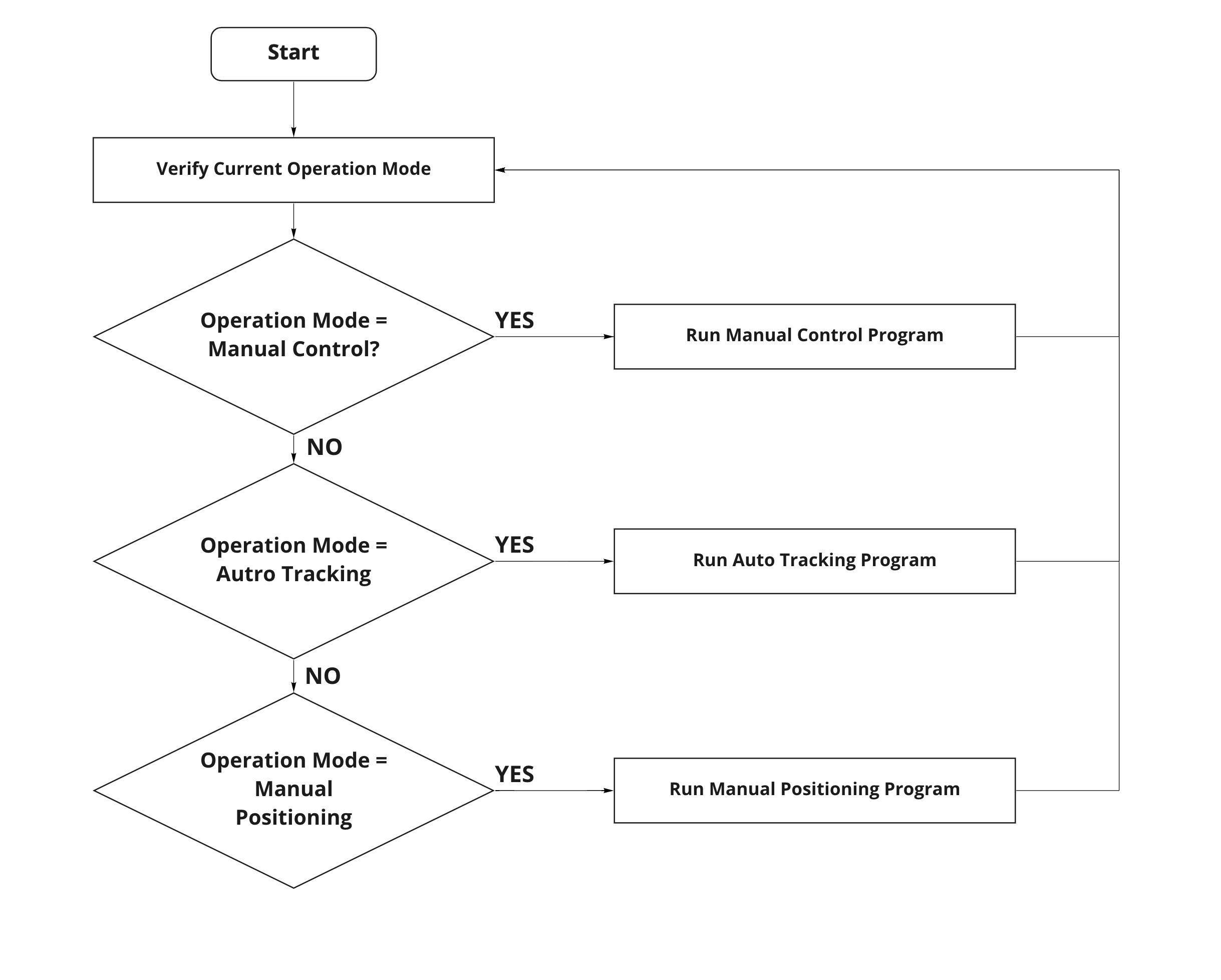

program_flowchart

Program Flowchart


The code responsible for delivering the phase 1 functionalities respects the following flow.
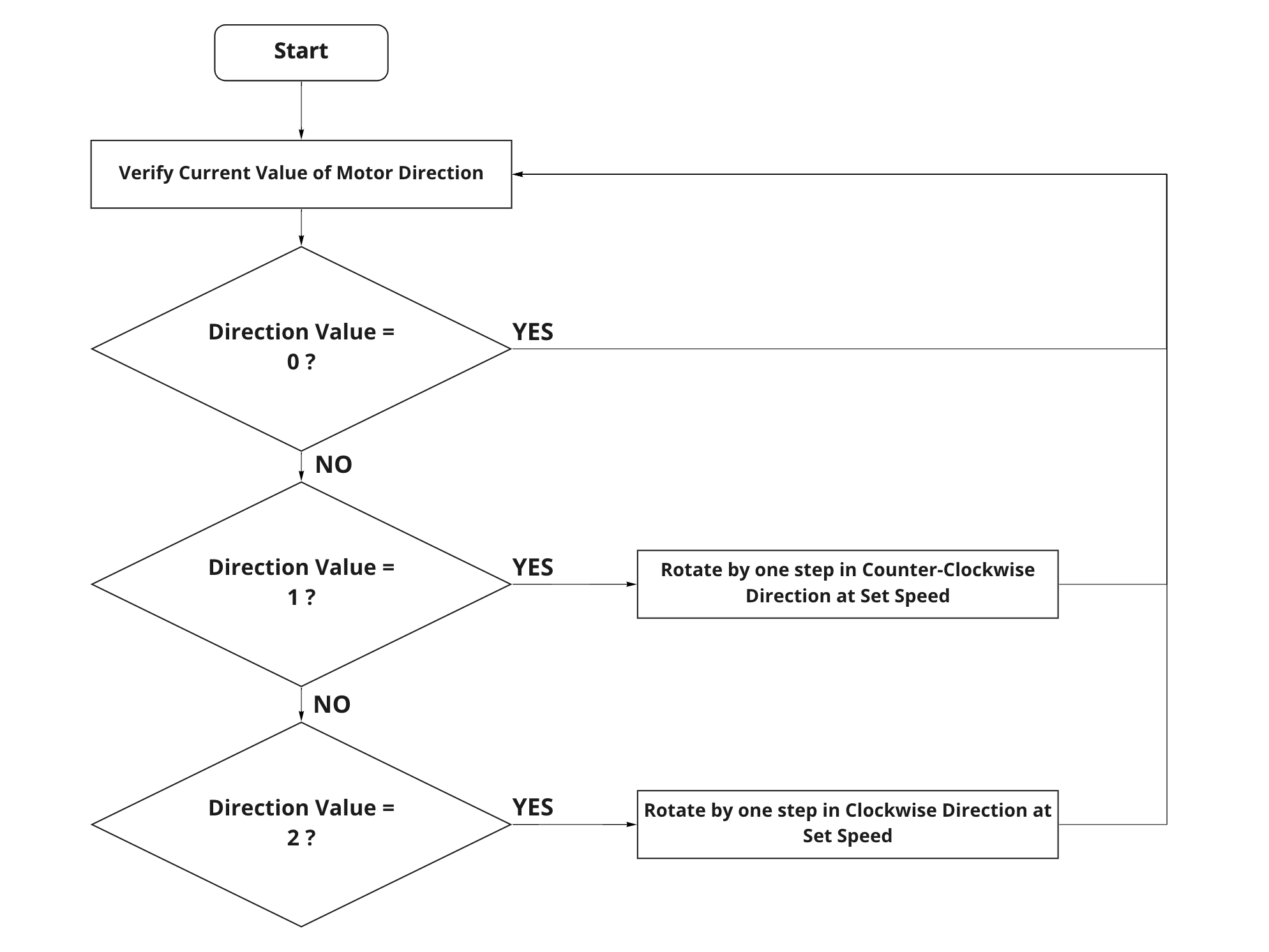

phase1_flowchart

Phase 1 Program Flowchart


  1
  2
  3
  4
  5
  6
  7
  8
  9
 10
 11
 12
 13
 14
 15
 16
 17
 18
 19
 20
 21
 22
 23
 24
 25
 26
 27
 28
 29
 30
 31
 32
 33
 34
 35
 36
 37
 38
 39
 40
 41
 42
 43
 44
 45
 46
 47
 48
 49
 50
 51
 52
 53
 54
 55
 56
 57
 58
 59
 60
 61
 62
 63
 64
 65
 66
 67
 68
 69
 70
 71
 72
 73
 74
 75
 76
 77
 78
 79
 80
 81
 82
 83
 84
 85
 86
 87
 88
 89
 90
 91
 92
 93
 94
 95
 96
 97
 98
 99
100
101
102
103
104
105
106
107
108
109
110
111
112
113
114
115
116
117
118
119
120
121
122
123
124
125
126
127
128
129
130
131
132
133
134
135
136
137
138
139
140
141
142
143
144
145
146
147
148
149
150
151
152
153
154
155
156
157
158
159
160
161
162
163
164
165
166
167
168
169
170
171
172
173
174
175
176
177
178
179
180
181
182
183
184
185
186
187
188
189
190
191
192
193
194
195
196
197
198
199
200
201
202
203
204
205
206
207
208
209
210
211
212
213
214
215
216
217
218
219
220
221
222
223
224
225
226
227
228
229
230
231
232
233
234
235
236
237
238
239
240
241
242
243
244
245
246
247
248
249
250
251
252
253
254
255
256
257
258
259
260
261
262
263
264
265
266
267
268
269
270
271
272
273
274
275
276
277
278
279
280
281
282
283
284
285
286
287
288
289
290
291
292
293
294
295
296
297
298
299
300
301
302
303
304
305
306
307
308
309
310
311
312
313
314
315
316
317
318
319
320
321
322
323
324
325
326
327
328
329
330
331
332
333
334
335
336
337
338
339
340
341
342
343
344
345
346
347
348
349
350
351
352
353
354
355
356
357
358
359
360
361
362
363
364
365
366
367
368
/*

 Author : Tarek Mahmoud

 Last Revision : 08/06/2021

 Version : 0.1

 */

// Initialisation of Libraries ____________________________________________________________________________________________________________________________________________________________________________________________________________________________________________

#include <WiFi.h>
#include "ESPAsyncWebServer.h"
#include <AsyncTCP.h>
#include <MultiStepper.h>
#include <AccelStepper.h>


// Initialisation of Variables ____________________________________________________________________________________________________________________________________________________________________________________________________________________________________________

// A - GPS & Compass

// Base GPS variables are initialised. Target variables will be intialised in server
double baseLongitude; double baseLatitude; double baseAltitude;

// Received from HTTP Post as
double targetLongitude; double targetLatitude; double targetAltitude; double targetSpeed;

// Compass

double baseAzimuth; double targetAzimuth;


// B - Manual Motor Control Commands

String postedMotorDirection; String postedMotorSpeed;

// D - Current Operation Mode - Defined by Phone App

int currentMode;

// E - WiFi Access Point

const char *ssid = "AutoTracking Camera Station";
const char *password = "1234abcde";

// Initialisation of server port
AsyncWebServer server(80);

// F - Stepper Motor

#define dirPin 32   // direction pin
#define stepPin 33    //step Pin
#define Motor_Enable 25 // Enable Pin

int motorDirection = 0;

int stepperSpeed =  100;

double stepsFraction = 1.00 / 1.00;
double fStepsPerRevolution = 200.00 / stepsFraction;

// Define a stepper and the pins it will use
AccelStepper stepper(AccelStepper::DRIVER, stepPin, dirPin);

// Custom Functions _______________________________________________________________________________________________________________________________________________________________________________________________________________________________________________________

double azimuthCalculator(double baseLong, double baseLat, double targetLong, double targetLat) {

  // Function used to determine the target Azimuth

  // Converting fron Degrees to Radians
  baseLong = baseLong * PI / 180;
  baseLat = baseLat * PI / 180;
  targetLat = targetLat * PI / 180;
  targetLong = targetLong * PI / 180;

  double deltaLong = targetLong - baseLong;
  double deltaLat = targetLat - baseLat;

  double A = sin(deltaLong) * cos(targetLat);
  double B = cos(baseLat) * sin(targetLat) - sin(baseLat) * cos(targetLat) * cos(deltaLong);

  // Converting Azimuth to degrees
  double O = atan2(A, B) * 180 / PI;

  if (O < 0) {
    O = 360 + O;
  }

  return O;
}


double motorStepsCalculator(double AzimuthA, double AzimuthB, double stepFraction) {

  // Function used to calculate the numer of steps required to align the motor's azimuth with the target azimuth

  double deltaAzim = AzimuthA - AzimuthB;

  if (deltaAzim < 0) {
    deltaAzim = 360 - deltaAzim;
  }

  double steps = deltaAzim / stepFraction;

  return steps * 100;
}


// Setup __________________________________________________________________________________________________________________________________________________________________________________________________________________________________________________________________
// ________________________________________________________________________________________________________________________________________________________________________________________________________________________________________________________________________

void setup() {

  Serial.begin(115200);
  Serial.println();

  // WiFi Network Set up
  Serial.println("Configuring access point...");
  WiFi.softAP(ssid, password);


  IPAddress myIP = WiFi.softAPIP();
  Serial.print("AP IP address: ");
  Serial.println(myIP);


  // Async Server - Post ____________________________________________________________________________________________________________________________________________________________________________________________________________________________________________________
  // ________________________________________________________________________________________________________________________________________________________________________________________________________________________________________________________________________


  // the below handle all post requests from the companion app.


  server.on("/control_mode", HTTP_POST, [](AsyncWebServerRequest * request) {},
  NULL,
  [](AsyncWebServerRequest * request, uint8_t *data, size_t len, size_t index, size_t total) {
    // Handling of data received.

    String controlMode;

    for (size_t i = 0; i < len; i++) {
      controlMode += (char)data[i];
    }

    currentMode = controlMode.toInt();

    switch (currentMode) {
      case 1:
        Serial.println("Auto-Tracking Mode");
        break;
      case 2:
        Serial.println("Manual Motor Control Mode");
        break;
      case 3:
        Serial.println("Manual Positioning Mode");
        break;
    }

    request->send(200);
  });


  server.on("/target_latitude", HTTP_POST, [](AsyncWebServerRequest * request) {},
  NULL,
  [](AsyncWebServerRequest * request, uint8_t *data, size_t len, size_t index, size_t total) {
    // Handling of data received.

    String targetLatitude;

    for (size_t i = 0; i < len; i++) {
      targetLatitude += (char)data[i];
    }
    targetLatitude = targetLatitude.toDouble();

    request->send(200);
  });


  server.on("/target_longitude", HTTP_POST, [](AsyncWebServerRequest * request) {},
  NULL,
  [](AsyncWebServerRequest * request, uint8_t *data, size_t len, size_t index, size_t total) {
    // Handling of data received.

    String targetLongitude;

    for (size_t i = 0; i < len; i++) {
      targetLongitude += (char)data[i];
    }
    targetLongitude = targetLongitude.toDouble();

    request->send(200);
  });


  server.on("/target_altitude", HTTP_POST, [](AsyncWebServerRequest * request) {},
  NULL,
  [](AsyncWebServerRequest * request, uint8_t *data, size_t len, size_t index, size_t total) {
    // Handling of data received.
    String  targetAltitude;

    for (size_t i = 0; i < len; i++) {
      targetAltitude += (char)data[i];
    }
    targetAltitude = targetAltitude.toDouble();
    Serial.println("Altitude Received");
    request->send(200);
  });


  server.on("/target_speed", HTTP_POST, [](AsyncWebServerRequest * request) {},
  NULL,
  [](AsyncWebServerRequest * request, uint8_t *data, size_t len, size_t index, size_t total) {
    // Handling of data received.
    String  targetSpeed;

    for (size_t i = 0; i < len; i++) {
      targetSpeed += (char)data[i];
    }
    targetSpeed = targetSpeed.toDouble();
    request->send(200);
  });

  server.on("/base_latitude", HTTP_POST, [](AsyncWebServerRequest * request) {},
  NULL,
  [](AsyncWebServerRequest * request, uint8_t *data, size_t len, size_t index, size_t total) {
    // Handling of data received.
    String  baseLatitude;

    for (size_t i = 0; i < len; i++) {
      baseLatitude += (char)data[i];
    }
    baseLatitude = baseLatitude.toDouble();

    request->send(200);
  });

  server.on("/base_longitude", HTTP_POST, [](AsyncWebServerRequest * request) {},
  NULL,
  [](AsyncWebServerRequest * request, uint8_t *data, size_t len, size_t index, size_t total) {
    // Handling of data received.
    String  baseLongitude;

    for (size_t i = 0; i < len; i++) {
      baseLongitude += (char)data[i];
    }
    baseLongitude = baseLongitude.toDouble();

    request->send(200);
  });


  server.on("/motor_speed", HTTP_POST, [](AsyncWebServerRequest * request) {},
  NULL,
  [](AsyncWebServerRequest * request, uint8_t *data, size_t len, size_t index, size_t total) {
    // Handling of data received.
    String postedMotorspeed;
    for (size_t i = 0; i < len; i++) {
      postedMotorSpeed += (char)data[i];
    }
    stepperSpeed = postedMotorSpeed.toInt();

    request->send(200);
  });


  server.on("/motor_direction", HTTP_POST, [](AsyncWebServerRequest * request) {},
  NULL,
  [](AsyncWebServerRequest * request, uint8_t *data, size_t len, size_t index, size_t total) {
    // Handling of data received.
    String postedMotorDirection;

    for (size_t i = 0; i < len; i++) {
      postedMotorDirection += (char)data[i];
    }
    motorDirection = postedMotorDirection.toInt();
    Serial.println(motorDirection);

    request->send(200);
  });

  // Async Server - Get _____________________________________________________________________________________________________________________________________________________________________________________________________________________________________________________
  // ________________________________________________________________________________________________________________________________________________________________________________________________________________________________________________________________________

  server.on("/base_latitude", HTTP_GET, [](AsyncWebServerRequest * request) {
    request->send_P(200, "text/plain", String(baseLatitude).c_str());
    Serial.print("Received GET request for board from client with IP: ");
    Serial.println(request->client()->remoteIP());
  });

  server.on("/base_longitude", HTTP_GET, [](AsyncWebServerRequest * request) {
    request->send_P(200, "text/plain", String(baseLongitude).c_str());
    Serial.print("Received GET request for board from client with IP: ");
    Serial.println(request->client()->remoteIP());
  });

  // ________________________________________________________________________________________________________________________________________________________________________________________________________________________________________________________________________
  // ________________________________________________________________________________________________________________________________________________________________________________________________________________________________________________________________________

  Serial.println("Starting Server on port 80");
  server.begin();
  Serial.println("Server Started");

  stepper.setMaxSpeed(1000);


}

// loop ___________________________________________________________________________________________________________________________________________________________________________________________________________________________________________________________________
// ________________________________________________________________________________________________________________________________________________________________________________________________________________________________________________________________________

void loop() {


  switch (currentMode) {

    case 1: //Auto-Tracking Mode

      targetAzimuth = azimuthCalculator(baseLongitude, baseLatitude, targetLongitude, targetLatitude);

      if (targetAzimuth == baseAzimuth) {
        break;
      } else {
        break;
      }

      break;


    case 2: // Manual Motor Control Mode

      if (motorDirection == 0) {
        break;

      } else if (motorDirection == 1) {

        Serial.println("Counter Clockwise Rotation");
        stepper.move(-1);
      }   else {

        Serial.println("Clockwise Rotation");
        stepper.move(1);

      }

      stepper.setSpeed(stepperSpeed);
      stepper.runSpeed();
      break;


    case 3: // Manual Positioning Mode

      break;
  }
}

Files


Last update: July 2, 2021