13. Networking & Communications
I. Individual Assignment
This week, I focused on developing a thorough understanding of WiFi communications. My goal is to determine how to send data over the air, form one device to another, using WiFi channels. My work centred around the ESP8266 platform which offers 2.4GHz WiFi hosting and stationing.
A. Producing the Boards
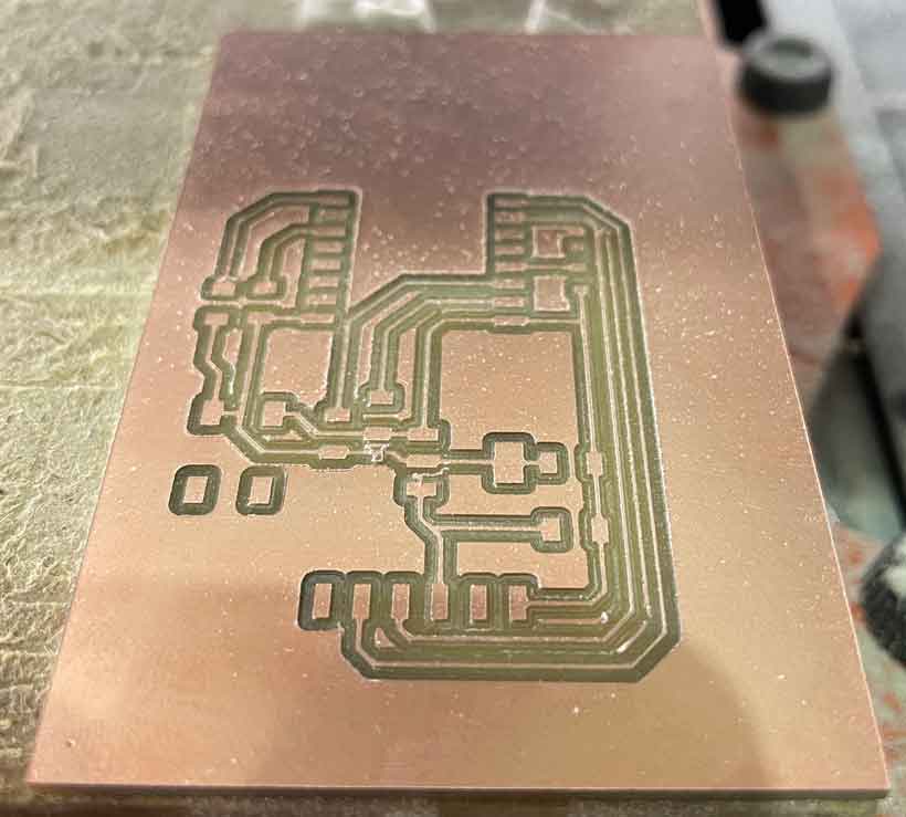
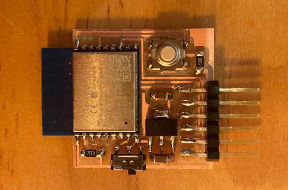
The Barcelona Fablab had a variety of modules based on the ESP8266. Namely the ESP12S, ESP WROOM 02D and the ESP8266XXX. This week’s course page included a complete example using the ESP WROOM 02D which included milling files and an Arduino sketch. I milled a board from these files but also designed a board around the ESP12S and milled it as well.
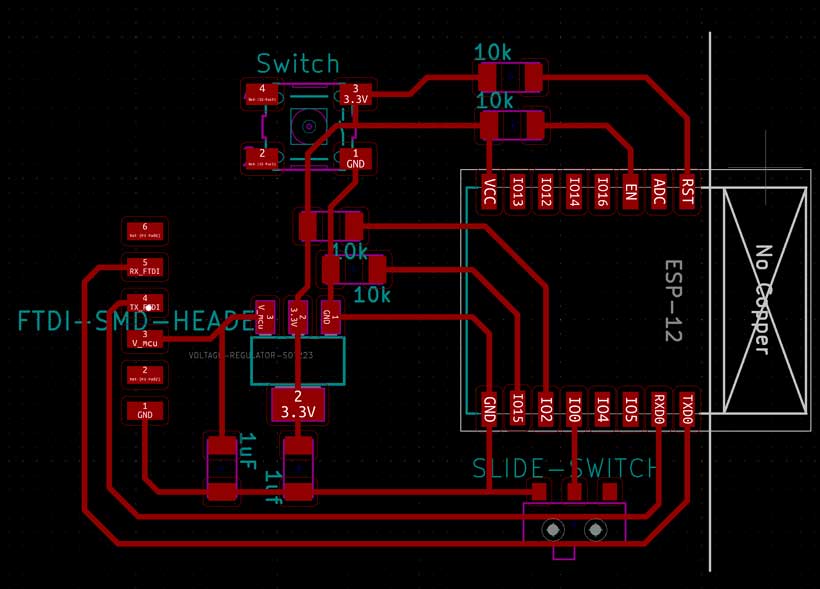
ESP12S
I based my design of the ESP12S board on that of the ESP WROOM 02D by Neil Gershenfeld (see below). I had to consider elements such as pin modes for flash boot and UART communication detailed in the below table. I also followed this manual provided by elcrow.com, as well as the information given on the board’s datasheet.
| GPIO15 | GPIO0 | GPIO2 | |
|---|---|---|---|
| UART (Serial Communication) | |||
| Flash Boot (Program Flash) |
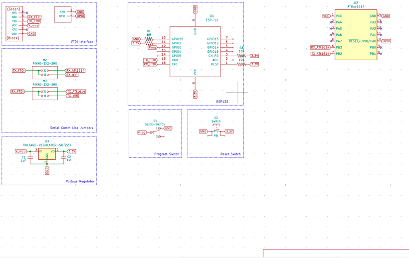
| Reference | Description | Quantity |
|---|---|---|
| ESP12S Module | WiFi module based on ESP8266 | |
| VReg | Voltage Regulator (3.3V @ 1A out) | |
| RST Switch | Button Switch used to reset board | |
| Prog Switch | Slide Switch used to set the board to external flash mode | |
| 10kΩ Res | 10 000 Ohms Resistors | |
| 1uF Cap | 1 micro Farad Capacitors | |
| FTDI Headers | Male pins used to interface with FTDI connector |
ESP Wroom 02D
This is a simple replica of the ESP WROOM 02D board provided on this week’s course page.

| Reference | Description | Quantity |
|---|---|---|
| ESP12S Module | WiFi module based on ESP8266 | |
| VReg | Voltage Regulator (3.3V @ 1A out) | |
| RST Switch | Button Switch used to reset board | |
| Prog Switch | Slide Switch used to set the board to external flash mode | |
| 10kΩ Res | 10 000 Ohms Resistors | |
| 1uF Cap | 1 micro Farad Capacitors | |
| FTDI Headers | Male pins used to interface with FTDI connector |
B. Establishing a WiFi network - AT Commands
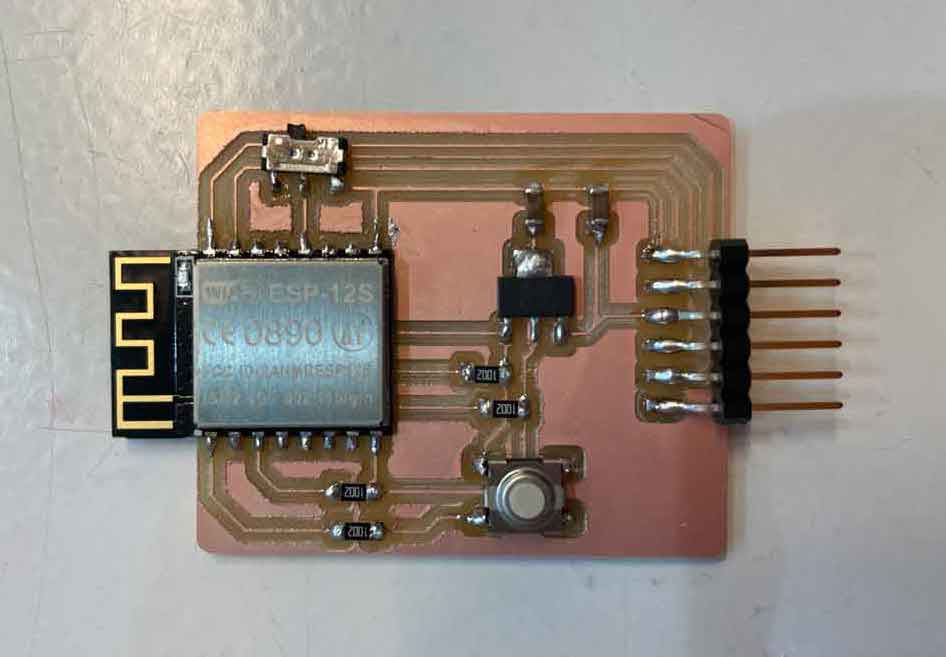
For once, milling went extremely well. No badly milled parts or broken end-mills :). I tested both boards at once by connecting them to my computer using an FTDI programmer for, each and they were both detected. Great success!
I now needed to try communicating with the boards. ESP8266 modules are pre-flashed with a firmware allowing them to be setup using specific commands from the Hayes command set, also known as the ATtention (or simply AT) command set. In short, a serial monitor can be used to input these commands to the board and set them up as desired.
My goal for this week was to have any type of data sent between devices on the same network. I first tried to set this using AT commands only.
1. Setting up a network through the Hayes command set
I worked on both boards in parallel. Arduino IDE’s serial monitor only allows for a single serial port to be monitored. To overcome this limitation, I downloaded (CoolTerm)[https://freeware.the-meiers.org/], a tool capable of exchanging data with several serial ports at the same time.
In order to create a WiFi network, I had to establish a hierarchy between my devices. Only one could act as an AccessPoint (AP) and host the network. The other would be setup as a client who accesses the network by connecting to the host.
First and foremost, I had to ensure the UART connection to the board was working. To do so I entered the startup test command:
AT
To which the board replied “OK”, indicating the link was working. I then obtained the firmware version using:
AT+GMR
Response
AT version:1.2.0.0(Jul 1 2016 20:04:45)
SDK version:1.5.4.1(39cb9a32)
Ai-Thinker Technology Co. Ltd.
Dec 2 2016 14:21:16
OK
Next, I had to configure the board as a host. ESP8266 can be configured to one of three modes assigned by numbers ranging form 1 to 3. Mode 1 configures the module as a station (client). Mode 2 configures it as a software enabled Access Point (softAP). Mode 3 as an AP and a Station (dual mode). I started by querying the board for its current mode through:
AT+CWMODE?
The board responded by indicating it was in mode 2 and was therefore already acting as a host. I therefore checked for its current SSID/Password configuration with:
AT+CWSAP?
Response
+CWSAP:”AI-THINKER_16886C”,”“,1,0,4,0
OK
which is equivalent to +CWSAP:SSID, Password, Channel ID, Encryption, Max number of stations, Current number of stations connected. Encryption can take values between 0 and 3, where:
0 = Open ; 1 = WPA_PSK ; 2 = WPA2_PSK ; 3 = WPA_WPA2_PSK
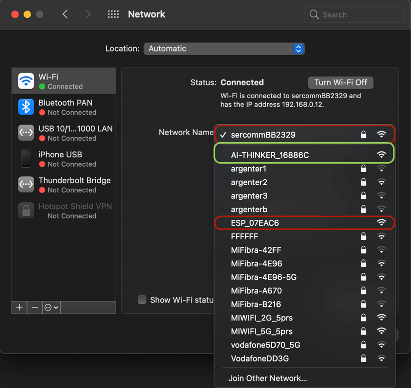
I checked the networks available within my laptop’s range and found one by the name “AI_THINKER_16886C” that did not require a password. This was it as the ESP-12S is manufactured and sold by a company called AI Thinker. I also found another open network called “ESP07EAC6” which was actually the other module. It seems both these boards were pre-configured as hosts.
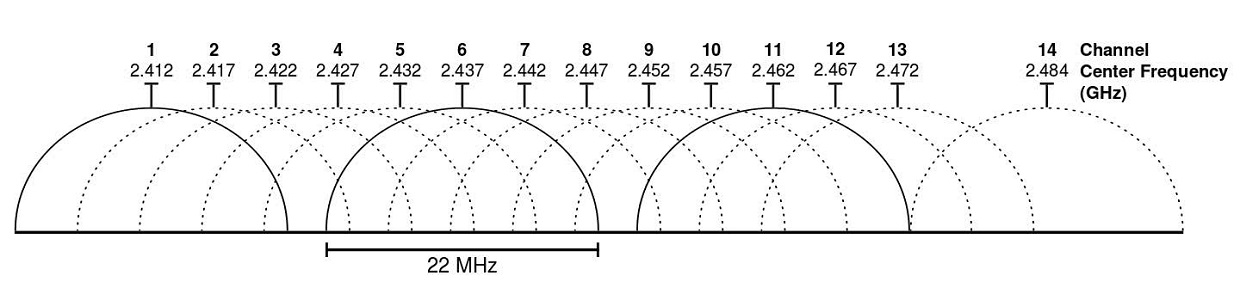
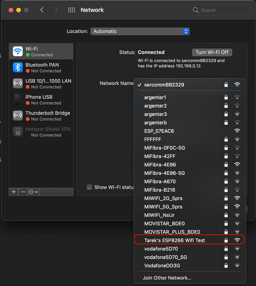
Next, I modfied the SSID to “ESP8266 Wifi Test” and added a password. I also set the encryption to WPA2 as it was the most secure. Furthermore, I scanned the 2.4 GHz wifi bandwave using macOS’s wireless diagnostoics tools (once app is open, head to window/scan and click scan) which determined that channel 11 was the most optimal. I therefore set my network on the 11th channel (2.462 GHz)
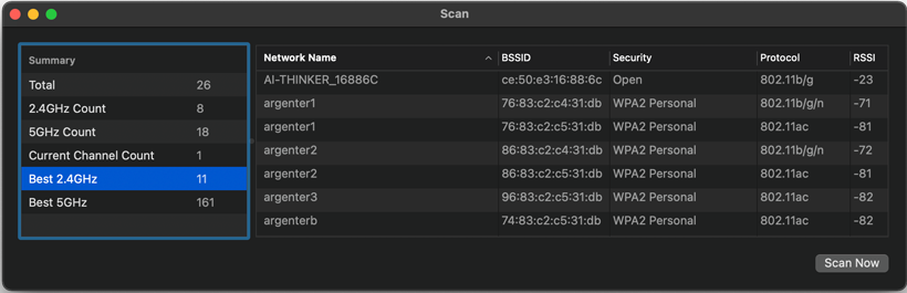
2.4 GHz WiFi Channels
AT+CWSAP=”ESP8266 Wifi Test”,”1234Test”,11,3
To confirm changes had been made, I used:
AT+CWSAP?
Response
+CWSAP:”Tarek’s ESP8266 Wifi Test”,”1234Test”,11,2,4,0
OK
Network was also available on my laptop’s list.
With that, the host configuration was done.
First and foremost, I had to ensure the UART connection to the board was working. To do so I entered the startup test command:
AT
To which the board replied “OK”, indicating the link was working. I then obtained the firmware version using:
AT+GMR
Response
AT version:1.6.2.0(Apr 13 2018 11:10:59) SDK version:2.2.1(6ab97e9) compile time:Jun 7 2018 19:34:26 Bin version(Wroom 02):1.6.2 OK
Much more recent versions than those of the ESP12S. Perhaps I’ll need to update the other board at one point. Nevertheless, I moved on and configured the board as a station using as it was currently set-up as a host:
AT+CWMODE=1
I then connected to the hose with:
AT+CWJAP=”ESP8266 Wifi Test”,”1234Test”
board responded that the connection was succesful with:
WIFI CONNECTED WIFI GOT IP
OK
I checked the connection type using:
AT+CIPSTATUS
which returned the following, meaning that the connection had been established and that an IP Address had been assigned to the station.
STATUS:2
OK
I checked the station’s IP address by entering “AT+CIFSR” which returned the IP and mac addresse.
AT+CIFSR
+CIFSR:APIP,”192.168.4.1”
+CIFSR:APMAC,”82:7d:3a:07:ea:c6”
Response
Station configuration was now complete.
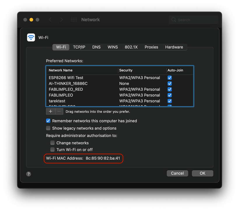
I also connected my computer and phone to the WiFi network. By using “AT+CWLIF”, I obtained a list of the IP and MAC addresses of all devices connected to the hub.
AT+CWLIF
192.168.4.2,cc:50:e3:16:88:6c
192.168.4.3,8c:85:90:82:ba:41
192.168.4.4,62:6d:2d:24:37:fb
I compared these values to those specified by the devices. The MAC address of my computer matched that of the second IP (192.168.4.3).
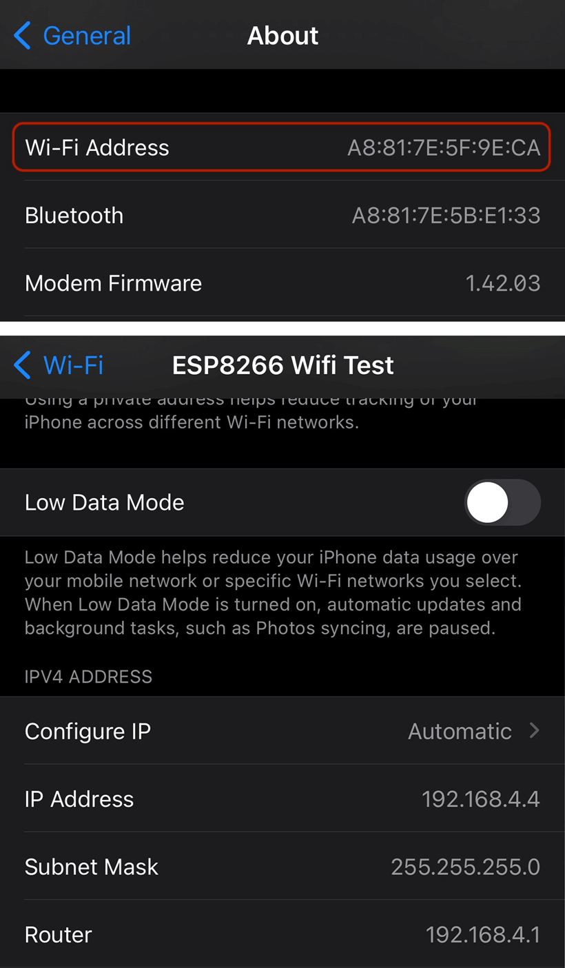
On the other hand, that of my phone matched none. I verified its assigned IP address which was the third (192.168.4.4). I am not exactly sure why. Perhaps I should look into it. But for now, I’ll focus on something else.
I finished by restoring both modules to their factory settings using
CT+RESTORE
2. Going Beyond.
Updating the board’s firmware
As
AT+CWJAP=”SSID”,”PASSWORD”
3. Conclusion
AT commands offer a simple way of setting up a WiFi network that does not require a complete program to be written. While I haven’t explored and tried the whole command set, I have a gotten a good idea of what can be done with them. If I were to continue working within the Hayes environment, I would like to use it to gain a better understanding of the whole WiFi protocol by limiting application abstractions to the bare minimum.
C. Communicating between stations.
Here, my goal is to send data between stations connected to a same network. Both ESP8266 modules I am using can be flashed through the ARDUINO IDE. My plan is to create a network with one of the modules through AT commands. I would then connect the other module and my Barduino to that network and have them communicate between each other.
1. Establishing and joining the network
I started by creating the network on the ESP-WROOM-02D using AT commands as described in previous section. Then, using the below code, I attempted to join the network through the Barduino’s ESP32.
1 2 3 4 5 6 7 8 9 10 11 12 13 14 15 16 17 18 19 20 21 22 23 24 25 26 27 28 29 30 31 32 | |
Connection was established successfully as both the station and host printed an event message through the serial port.
+STA_CONNECTED:”c8:2b:96:9f:a5:c8”
+DIST_STA_IP:”c8:2b:96:9f:a5:c8”,”192.168.4.2”
15:02:27.934 -> Connecting.....
15:02:30.432 -> Connected to ESP8266 Wifi Test
15:02:30.432 -> IP Address: 192.168.4.2
Sending AT Commands to Host Device through Arduino Program (TO DO)
example
https://circuitdigest.com/microcontroller-projects/sending-arduino-data-to-webpage
2. Data Transfer
HTTP Requests - Asynchronous Server
One way of storing data to be accessed by other stations within the network is to use the application-layer Hypertext Transfer Protocol (or HTTP). In essence, specific chunks of data are given an HTTP address which can be accessed externally. A tutorial by randomnerdtutorials.com, which can be found here details how to achieve this using ESP8266 modules. Seeing as I am also using an ESP32, some commands had to be replaced. I used this ESP32 WiFi command guide to figure out which.
The tutorial works on setting up an Asynchronous Server. Asynchronous servers can process multiple requests without creating dedicated threads (which I assume to mean connection lines). Instead, they process multiple requests at once, preventing the blocking of other requests., contrary to synchronous servers in which each connection is assigned a single thread until its request has been successfully processed. I’ll compare this Asynchronous setup to a regular synchronous one.
(Explanation 3 - Simplest to understand),
(Explanation 4 - Good as well)
Essential Libraries
I had to Download the following libraries to make the code work.
Setting up a Server
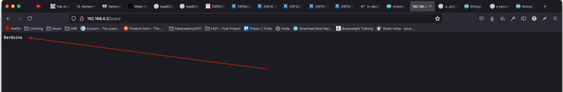
I wrote a program based on that of the randomnerdtutorials and uploaded it to the Barduino. The code simply creates an HTML address at which the board’s name is stored. This HTML can be found within the asynchronous server hosted by the board on which the program is flashed.
ESP8266 Conversion
To use this program with an ESP8266, simply replace #include
1 2 3 4 5 6 7 8 9 10 11 12 13 14 15 16 17 18 19 20 21 22 23 24 25 26 27 28 29 30 31 32 33 34 35 36 37 38 39 40 41 42 43 44 45 46 47 48 49 50 51 52 53 54 55 56 57 58 59 60 61 62 63 64 | |
Once the board had been flashed and connected to the network, I could verify the contents of the HTML address form my computer. To do so, I needed to connect to the network and then access “192.168.4.2/board” from my web browser.
The initial trials failed because I had not properly set the server request handle, causing the browser to be unable to open the HTML page. One thing that was essential was to ensure the data to be displayed on the HTML address was a string that would be converted to a C based string using the “.c_str()” extension. As shown below:
server.on(“/board”, HTTP_GET, {
request->send_P(200, “text/plain”, String(header).c_str());
});
Having corrected this, I tried again, and it worked.
Now onto the Client
Setting up a Client
Using the same tutorial as reference, I wrote the following code and flashed it to the ESP12S, which uses an ESP8266 module.
Pre-requisites
- Downloaded all ESP8266 libraries from ESP8266 Community Arduino Resources
- Used V2.5.0 ESP8266 Boards Package - I would get compilation errors using the latest version. This version is known to work in this perticular context.
1 2 3 4 5 6 7 8 9 10 11 12 13 14 15 16 17 18 19 20 21 22 23 24 25 26 27 28 29 30 31 32 33 34 35 36 37 38 39 40 41 42 43 44 45 46 47 48 49 50 51 52 53 54 55 56 57 58 59 60 61 62 63 64 65 66 67 68 69 70 71 72 73 74 75 76 77 78 79 80 81 82 83 84 85 86 87 88 89 | |
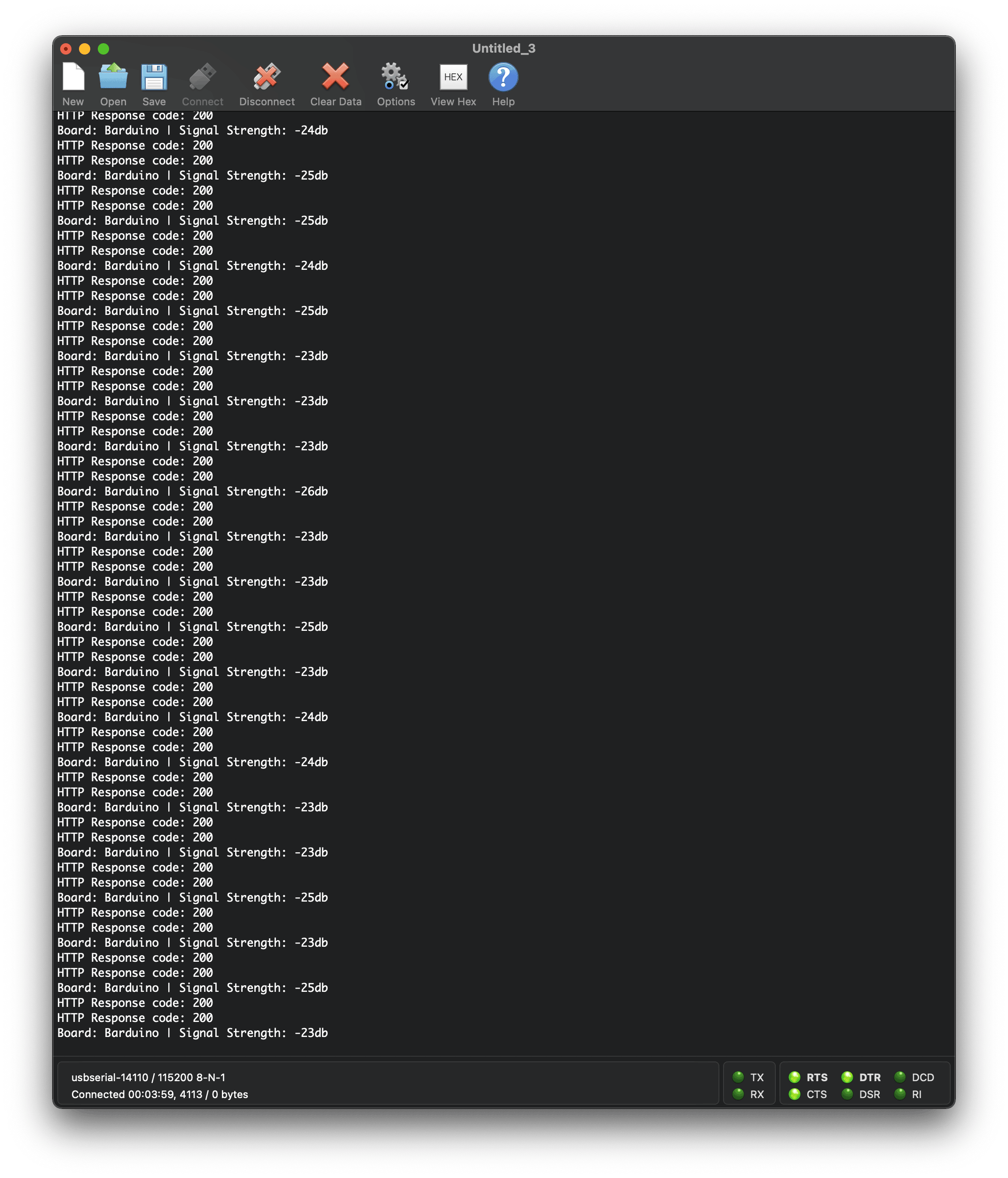
The program requests the values located at “192.164.4.2/board” and “192.164.4.2/rssi”, then displays them on the serial monitor, as shown below.
HHTP Data Requests - Synchronous Server (TO DO)
Example https://robotzero.one/sending-data-esp8266-to-esp8266/
HHTP Data Posts (TO DO)
Example https://circuitdigest.com/microcontroller-projects/sending-arduino-data-to-webpage
3. Summary
Structure
Server (Hosting Data)
Client (Looking to exchange data with Server)
Get = obtaining data from server through specific Requests
Post = Obtaining permission from server to send additional data.
II. Group Assignment
Please refer to Adrien Laveau’s comprehensive documentation for a summary of the different networking protocols considered this week.
Adrien connected to my network with his own version of the Barduino
III. Files & Resources
Files
Files for Week 13
WiFi Server Arduino Sketch for ESP32
WiFi Client Arduino Sketch for ESP8266
WiFi AT Commands for ESP8266 Platform - Cheat Sheet
Links
AT-Commands
Guide by ESPRESSIF - https://docs.espressif.com/_/downloads/esp-at/en/release-v2.1.0.0_esp32s2/pdf/
Guide by deviceplus - https://www.deviceplus.com/arduino/esp-wroom-02-wifi-setup-guide-at-commands/
Guide by Room15 - http://room-15.github.io/blog/2015/03/26/esp8266-at-command-reference/#AT+CIPSEND
Comprehensive list of AT commands (most are not relevant to the ESP8266 platform) - https://m2msupport.net/m2msupport/atchld-call-related-supplementary-services/
ESP 8266 Platform
AT Firmware Download - https://www.espressif.com/en/support/download/at?keys=&field_type_tid%5B%5D=14
Guide on Flashing AT firmware - https://www.allaboutcircuits.com/projects/flashing-the-ESP-01-firmware-to-SDK-v2.0.0-is-easier-now
Sending data over WiFi using a sketch - https://robotzero.one/sending-data-esp8266-to-esp8266/
ESP-12S
Datasheet - https://docs.ai-thinker.com/_media/esp8266/docs/esp-12s_product_specification_en.pdf
User Manual - https://www.elecrow.com/download/ESP-12S_User_Manual.pdf
ESP-WROOM-02D
Datasheet - https://www.espressif.com/sites/default/files/documentation/esp-wroom-02u_esp-wroom-02d_datasheet_en.pdf
ESP32
Useful Wifi Commands - https://randomnerdtutorials.com/esp32-useful-wi-fi-functions-arduino/
WiFi ESP Tutorials*
ESP32 Client Server - https://randomnerdtutorials.com/esp32-client-server-wi-fi/ ESP32 AP Web Server - https://randomnerdtutorials.com/esp32-access-point-ap-web-server/ ESP32 Web Server Arduino - https://randomnerdtutorials.com/esp32-web-server-arduino-ide/ ESP8266 Asynchronous Web Server - https://randomnerdtutorials.com/esp8266-nodemcu-client-server-wi-fi/
Ultra Wide Band (UWB)
https://www.youtube.com/watch?v=TR-rahy3Y2k
https://www.youtube.com/watch?v=zA27p0Pj30U
https://www.mouser.es/ProductDetail/Qorvo/DWM1000?qs=%2Fha2pyFadugIGSS%2FR%2FAb6A41XE%2FOZPGGKI5qaaSRY3o%3D
https://www.mouser.es/ProductDetail/Qorvo/DWM1004C?qs=sPbYRqrBIVldx%2FKFDrxv5Q%3D%3D
https://www.mouser.es/ProductDetail/Qorvo/DWM3000TR13?qs=hWgE7mdIu5QrWWDEt6OFQw%3D%3D