4. Electronics Production
This week’s work revolved around the milling and soldering of our own Plastic Circuit Boards (PCB). We were given a brief lecture on the required processes and basic concepts of electronics, followed by hands on soldering and milling demonstrations and exercises. Once completed, we focused on completing the assigned group and individual tasks.
I. Group Assignment
- Characterize the design rules for your PCB production process
1. Preping test files on mods
The milling machines available at FabLab BCN are the Roland SRM-20 and Seinsmart Genmitsu CNC router. G-Code is used to program and sequence the [xxx] whereas the SRM-20 uses RML-1 code, but is G-Code compatible. We tested both in order to determine the characteristics of each machine. The PCBs used are composed of a rigid and rectangular plastic core sandwiched by copper layers.
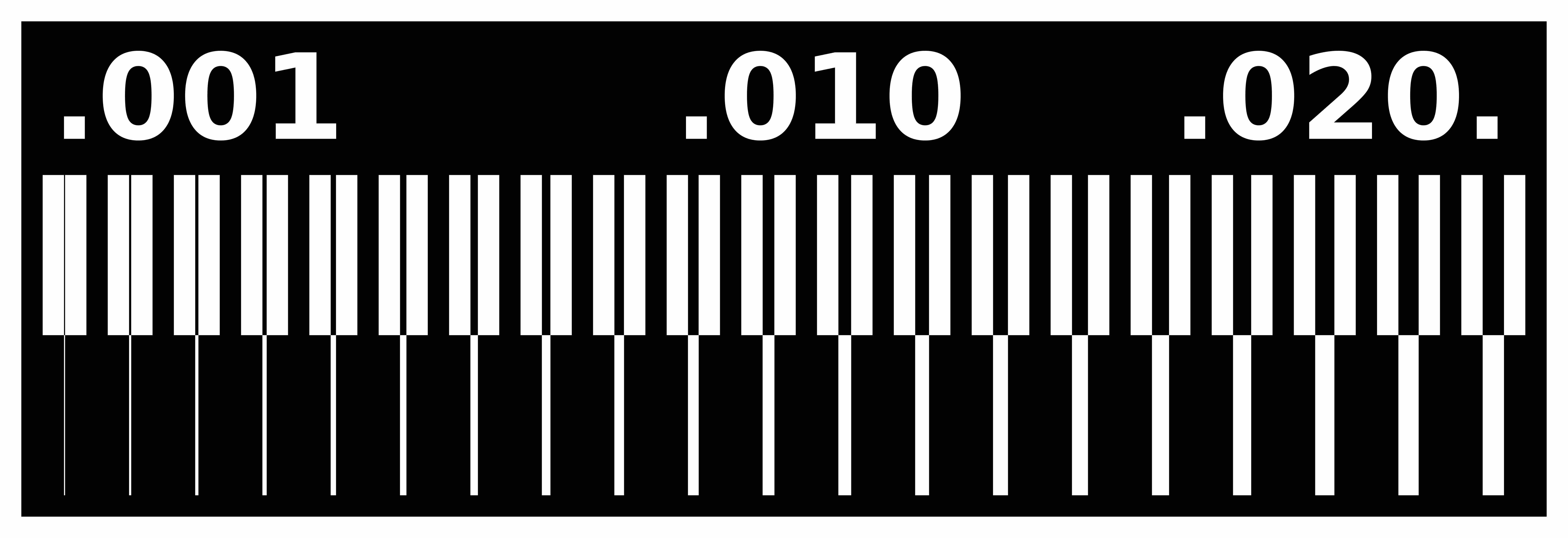
For this assignment, we were provided with files that would allow us to test the effectiveness of the available tools in producing traces of small to large width. These were in .PNG format and needed to be translated into the corresponding numerical control code (G or RML-1). This was achieved by means of mods, an in-browser tool developed by the CBA at MIT.
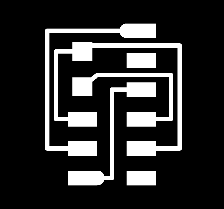
The test included traces and interior components, each having its own .PNG file. Traces defines the internal copper circuits. Interior outlines the edges of the board. Thus, the first is determines what parts of the copper layer are to be milled to produce the desired circuitry. The latter defines the board’s boundary lines to mill it out from the initial piece of PCB materials.

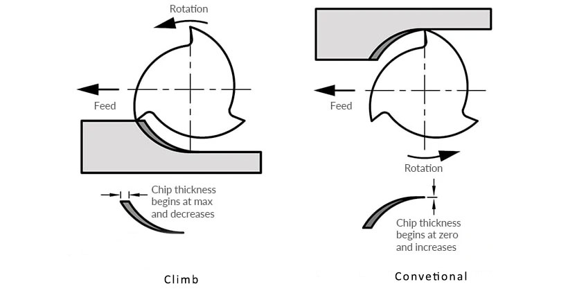
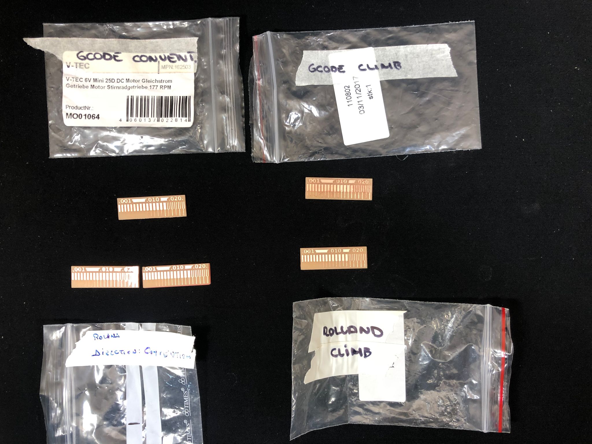
One fundamental milling concept we needed to compare was the milling direction, which defines the direction in which the end-mill rotates with regards to the material feed. Milling can be achieved in what are known as the conventional direction and the climb direction.
In the conventional direction, the milling tool cuts the material from the inside, pushing out the removed pieces, also referred to as chips, in front of it. In other terms, it “digs out”. In contrast, in the climb direction, the milling tool strikes the cutting surface, and pushes the chips to its back. It “digs in”. Conventional milling used to be preferred as it eliminated the backlash caused by the tool hitting the cutting surface. However, most machines now compensate for this and the climb direction has now become widely used. amongst its benefits are that it increases the tool’s life. Source
Therefore, we compared both conventional and climb on both machines.
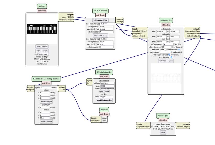
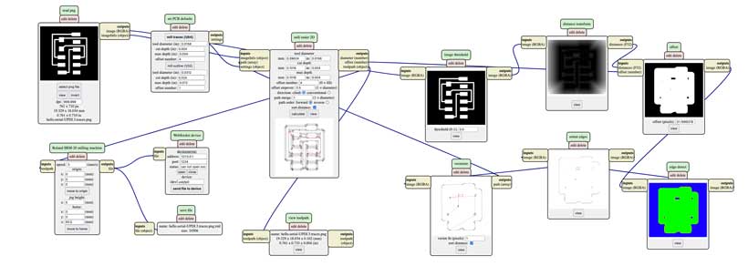
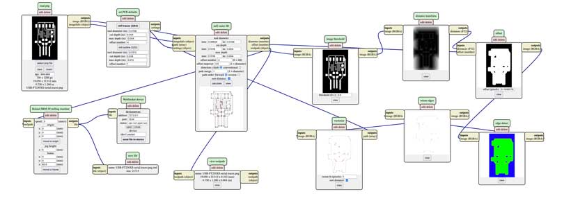
Mods uses a visual network of tools, or program, to process files. For this week’s assignment, we only focused on a handful of these.
We first had to load the proper program. Right clicking on the workspace brings out a menu. Fromm there we needed to head to programs/open server program/SRM20 PCB PNG. This loaded the program shown below.
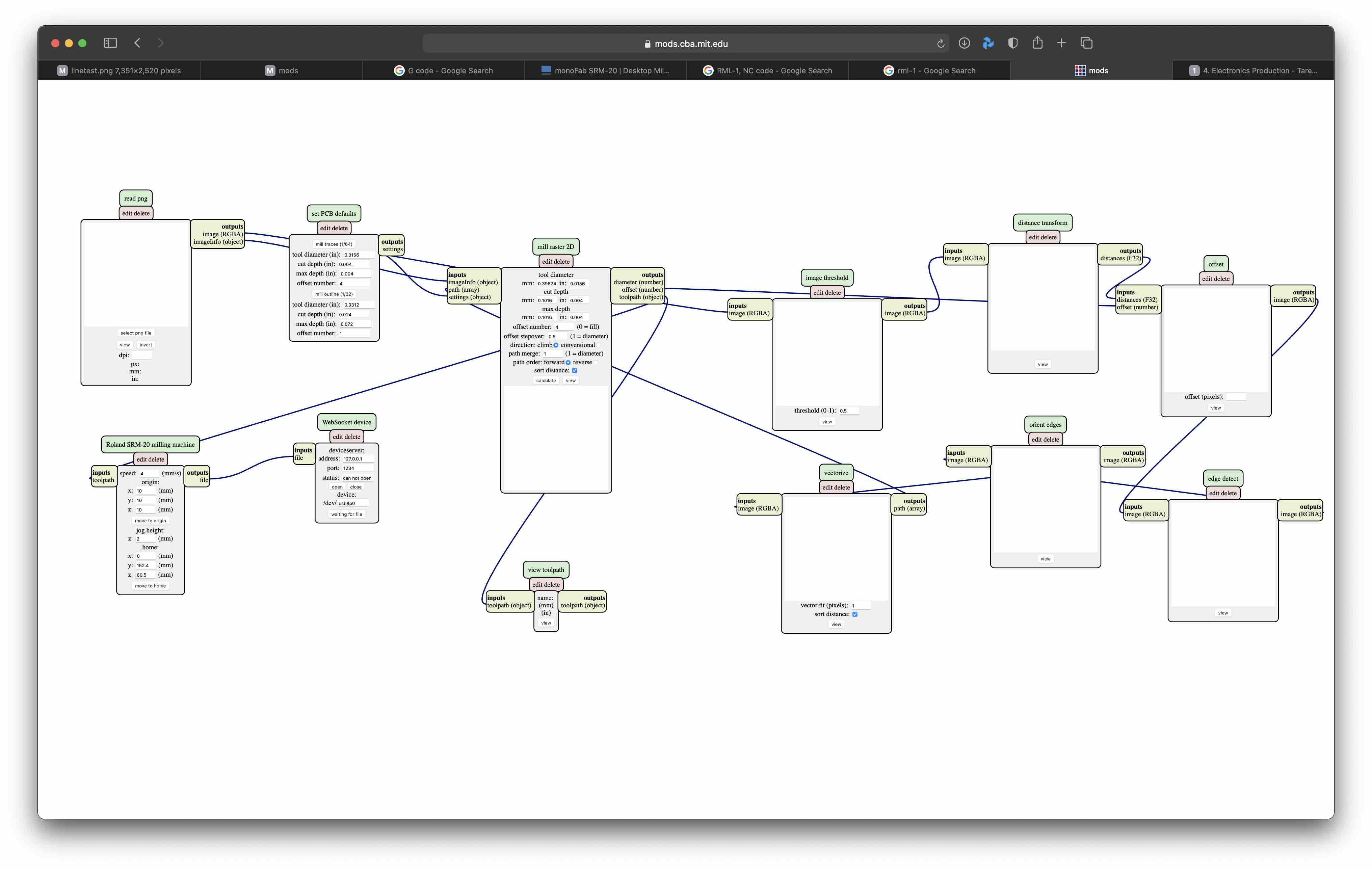
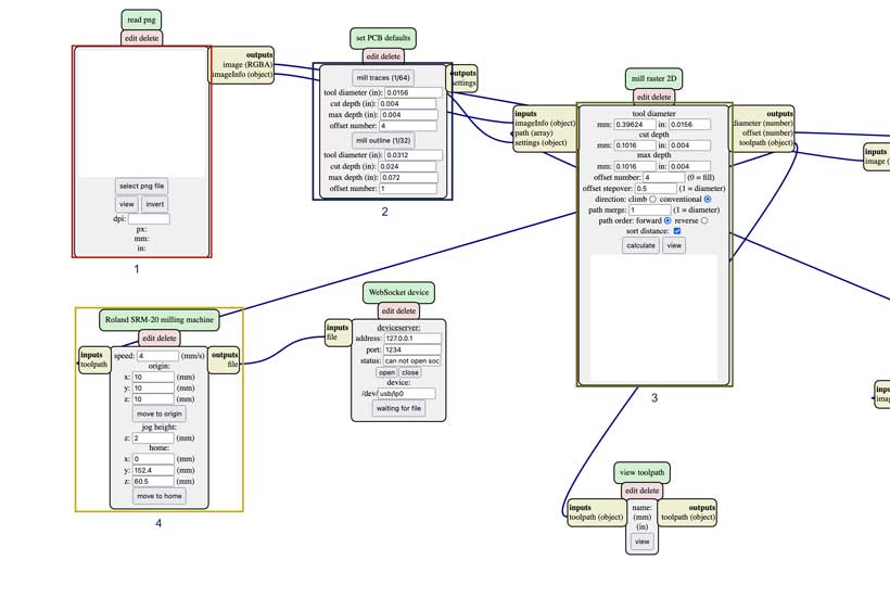
We only focused on four of the tools in the above network. These are the PNG reader (Red), end-mill selector (Blue), tool-path calculator (Green) and Machine parameter selector (Orange), and were used in that following order.
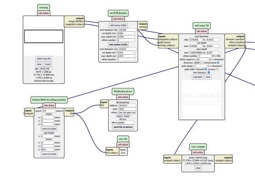
Below are the cut parameters used for the traces and outline cuts. The main differences between each was the tool selected and speed, which were of 1/64 mill at 3mm/s and 1/32 mill at 0.5 mm/s for the traces and outline, respectively.
2. Milling the Test Boards.
b. Milling procedure
I worked with Adrian on the conventional cut with the Roland SRM-20.
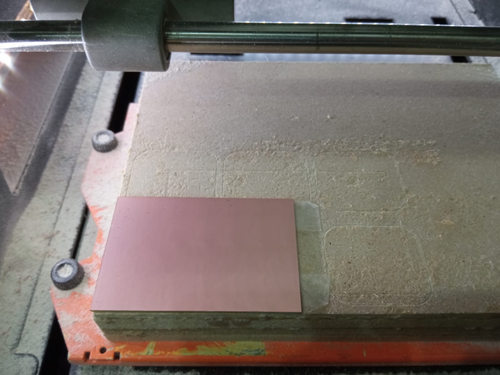
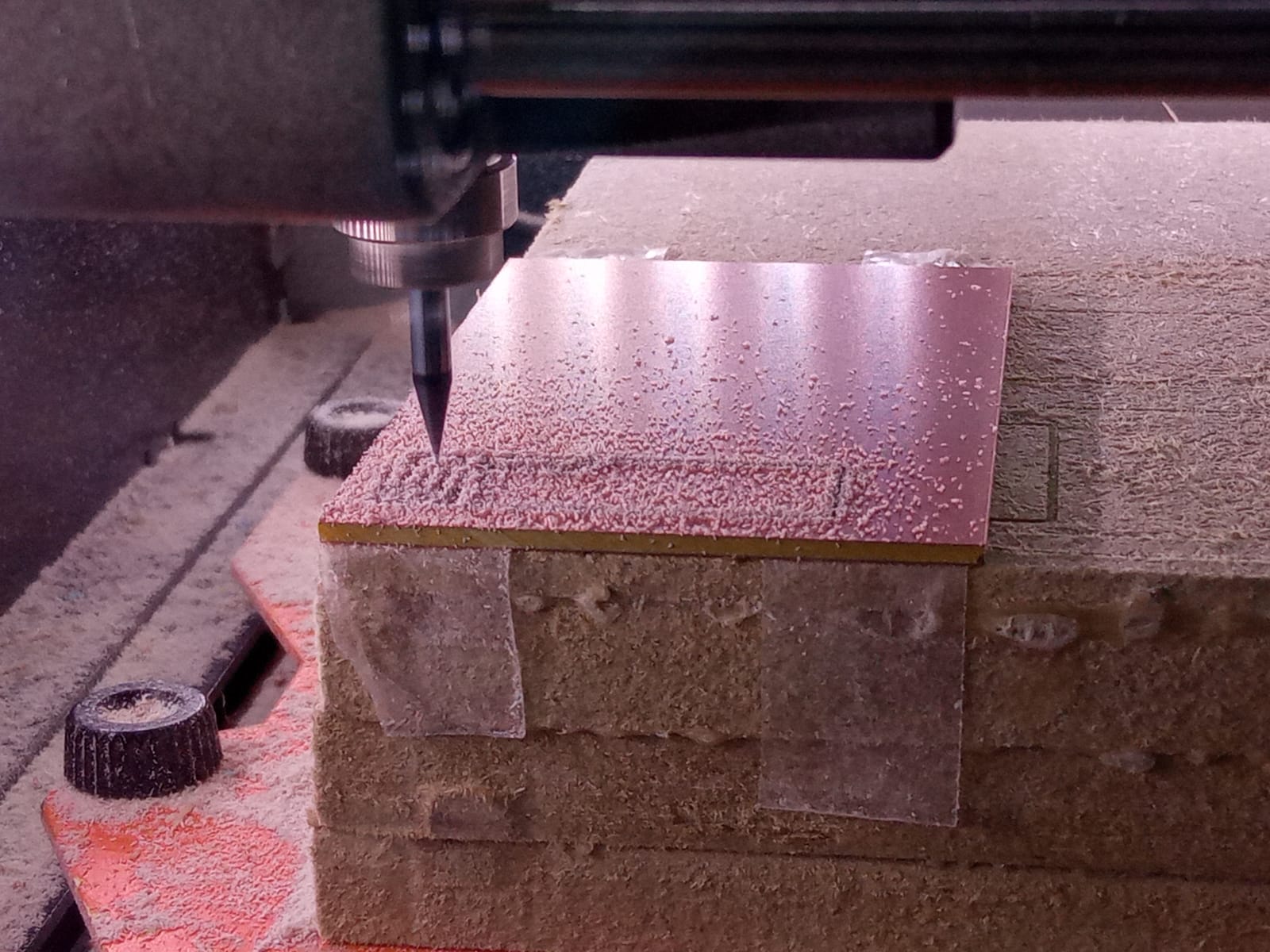
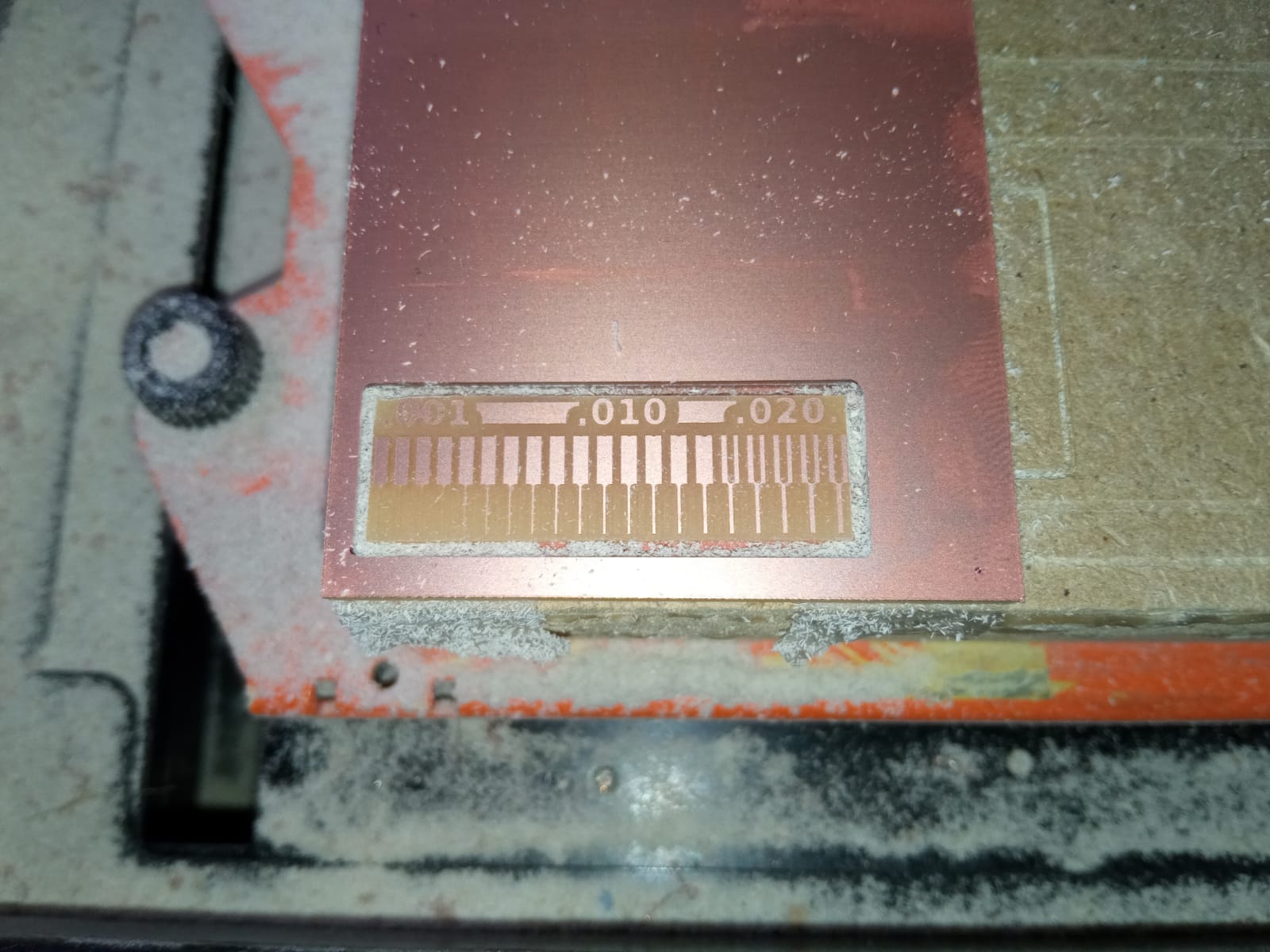
The conventional cut with the Roland SRM-20 offered the cleanest results.
3. PCB Milling Rules and Summary
Process (From existing traces/internal files)
a. Create or locate files for desired PCB configuration.
b. Upload the files in mods.
c. Select the end-mill to be used (1/64 for traces; 1/32 for internal).
d. Select the desired milling direction.
e. Extract Machine control code in a format compatible with machine to be used.
d. Place board on the required surface.
e. Initialise machine and set zero point in X, Y and Z coordinates from corresponding software. - XXX for SRM20 - XXX for XXX
f. Launch milling process, starting with traces (1/64 end-mill) followed with interior (1/32 end-mill).
Things to Consider
-
To ensure proper milling of the Copper and Plastic layers, verify the following have been respected:
-
End-mills have been tightly attached.
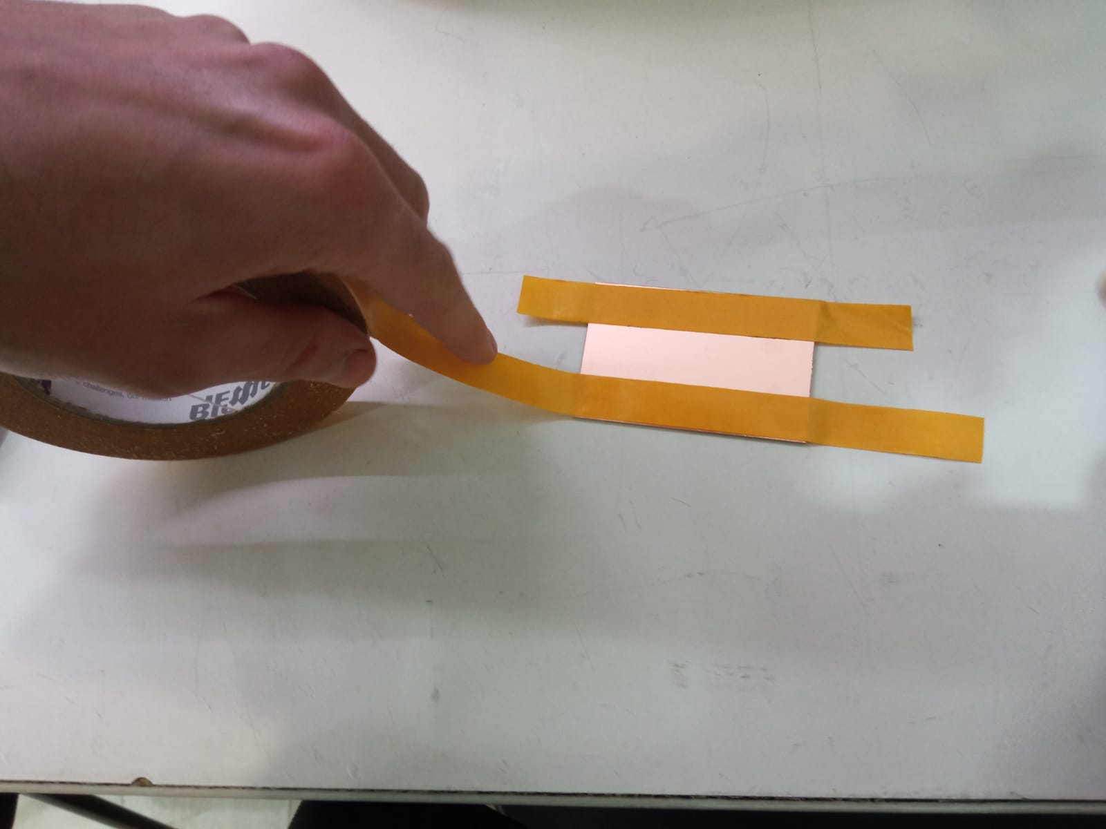
- PCB is laid flat on support surface. If using double sided tape, align tape’s mid-line with edge of board.
- If milling multiple boards, set zero in Z direction towards the midpoint of the distance seperating boards.
II. Individual Assignment
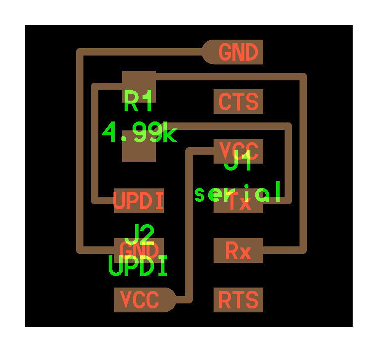
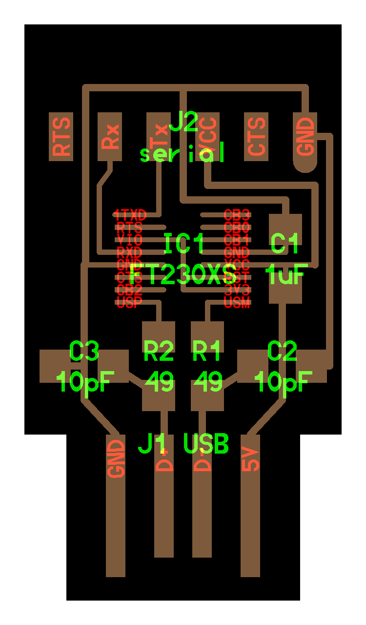
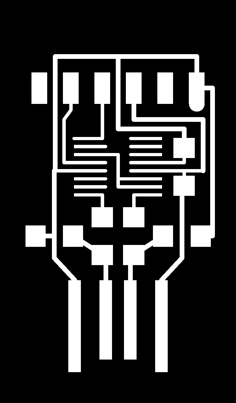
For this week’s assignment, I decided to mill both an FTDI and a UPDI board on the SRM-20.
a. Preping the files
The UPDI board I picked also possessed a VCC line that could program on its own any programmable board with a UPDI interface.


b. The hell mill
I encountered a couple of issues while milling and soldering both the boards.
The first two had missing tracks. This was due to one of the two machines being inconsistent with its cut. It tried again with the second machine we had at the lab and never encountered the same issue.
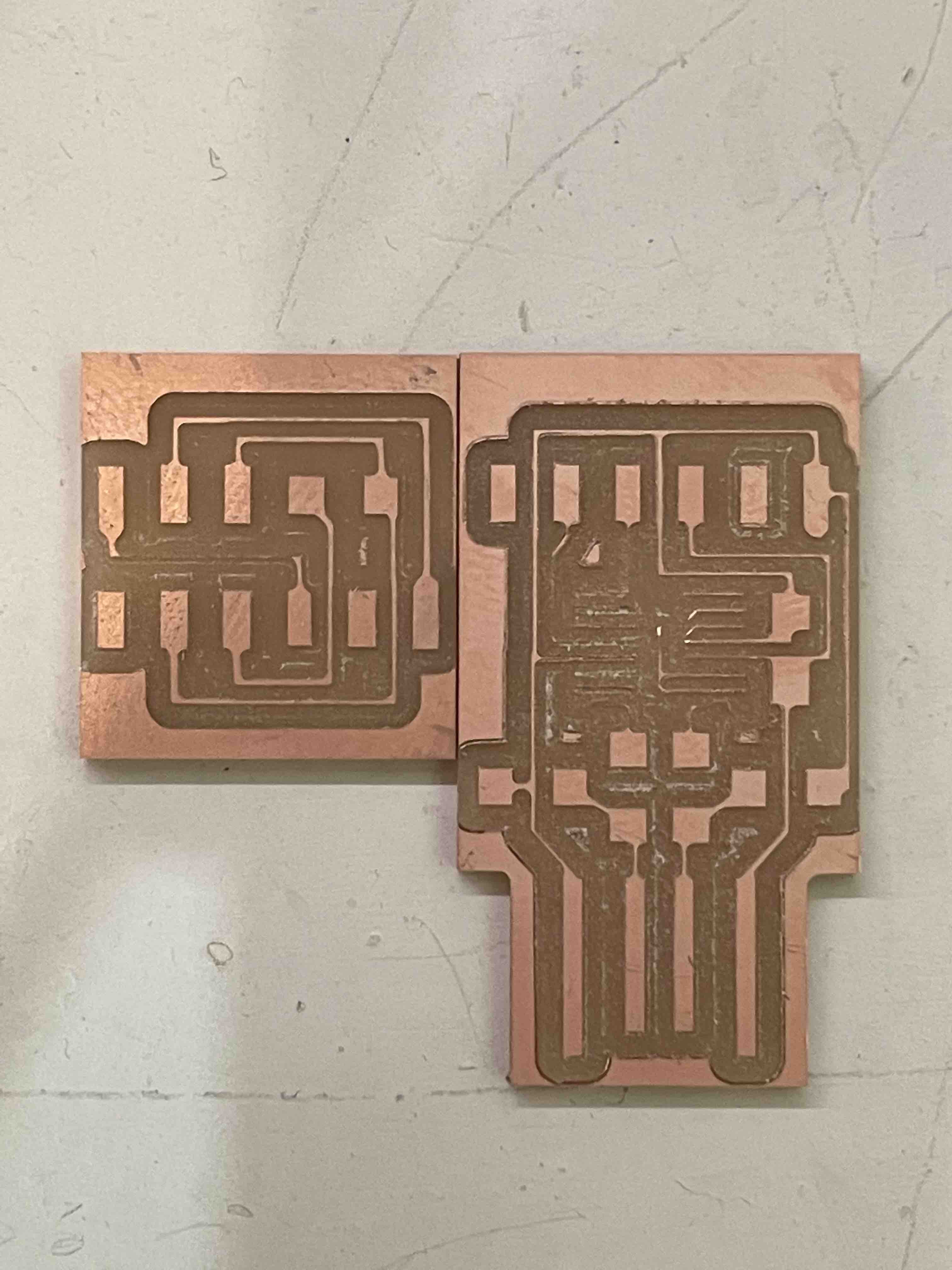
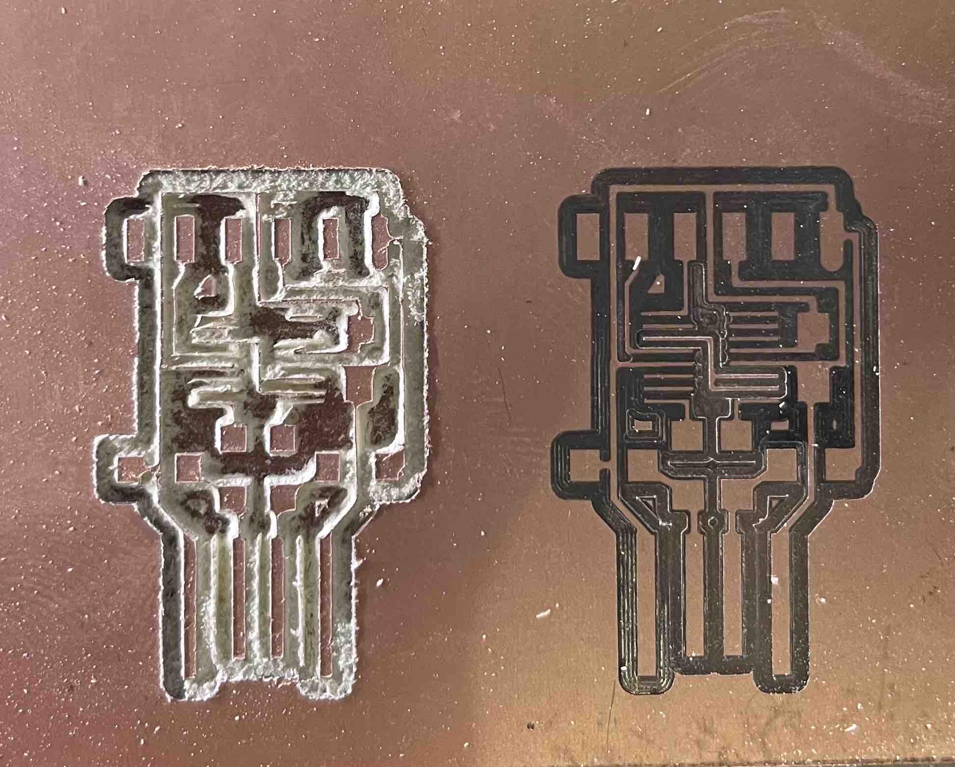
Another issue I encountered was an improper setting of the tool’s zero position in the Z direction. In fact, I both set it too low (Left board), and too high (Right Board). This led to deep tracks on the one hand, which miraculously didn’t break my 1/64 end mill, and on the other hand, a residual layer of copper which rendered the board not usable.
My fourth try worked perfectly. However, as I was soldering the FT230XS chip, I tore one of its tracks off and had to mill the board again, for a fifth time :’/
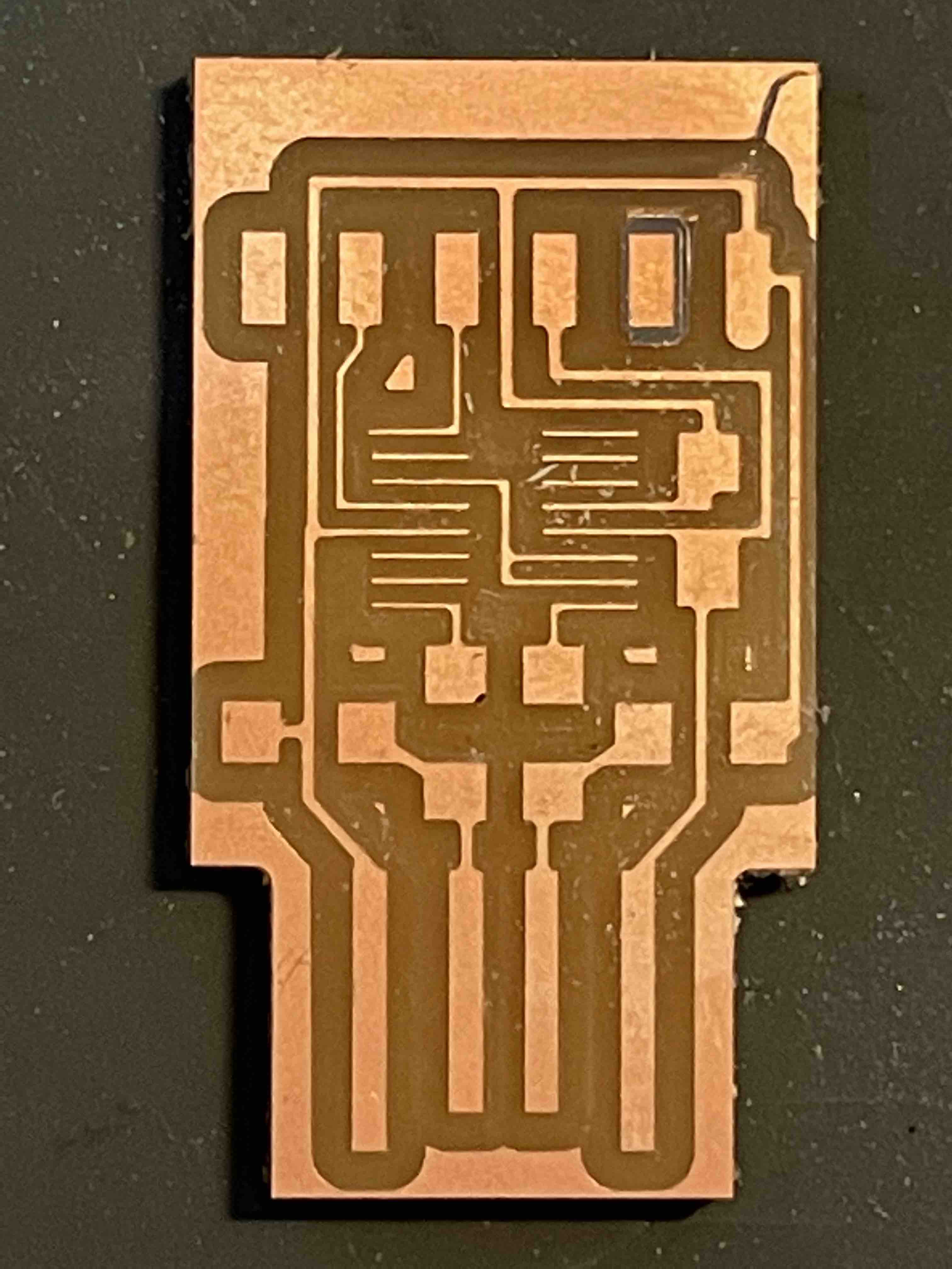
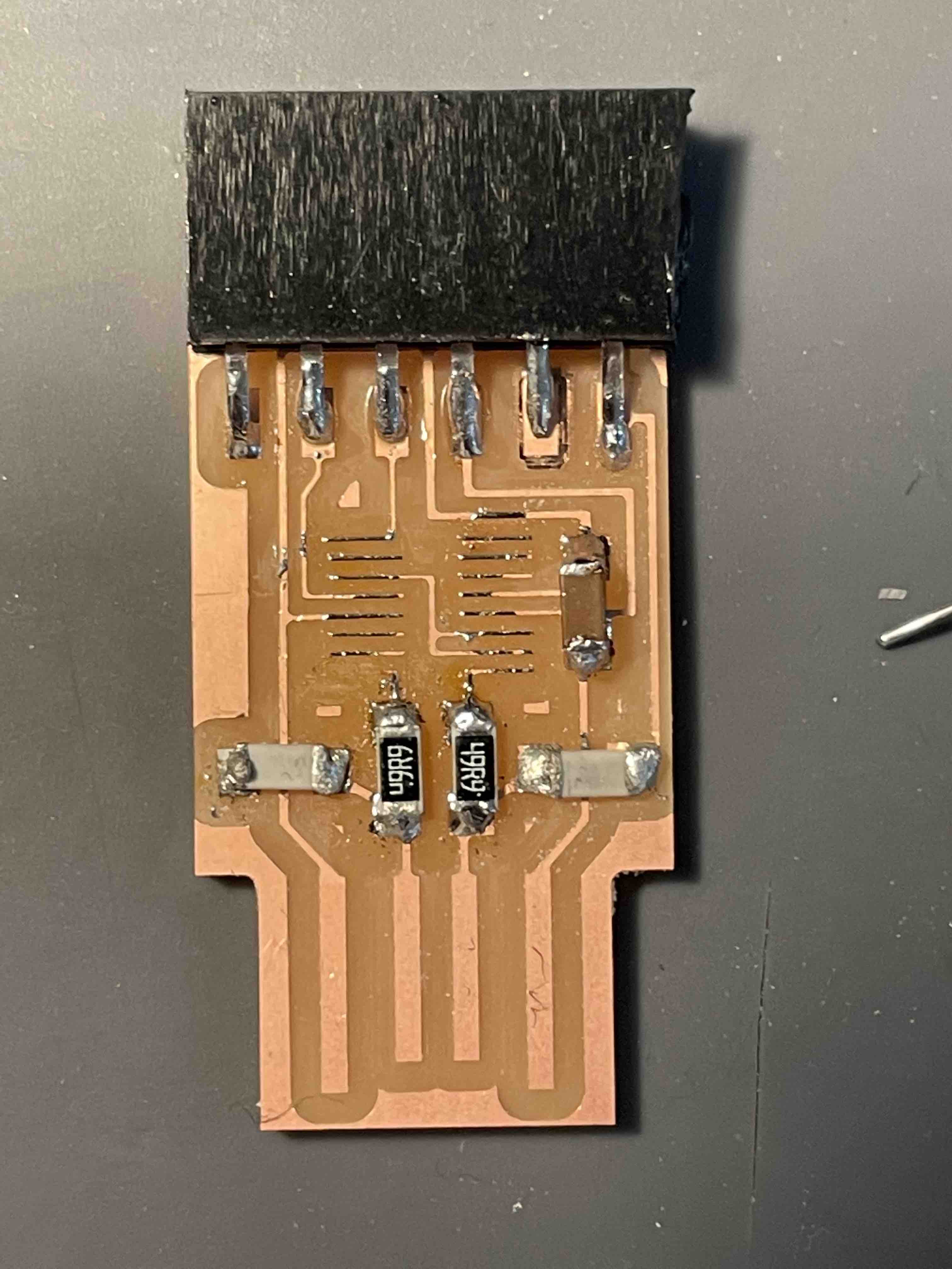
I was now a scarred but experienced veteran. My fifth try was the right one. Below are picture of the soldered boards.
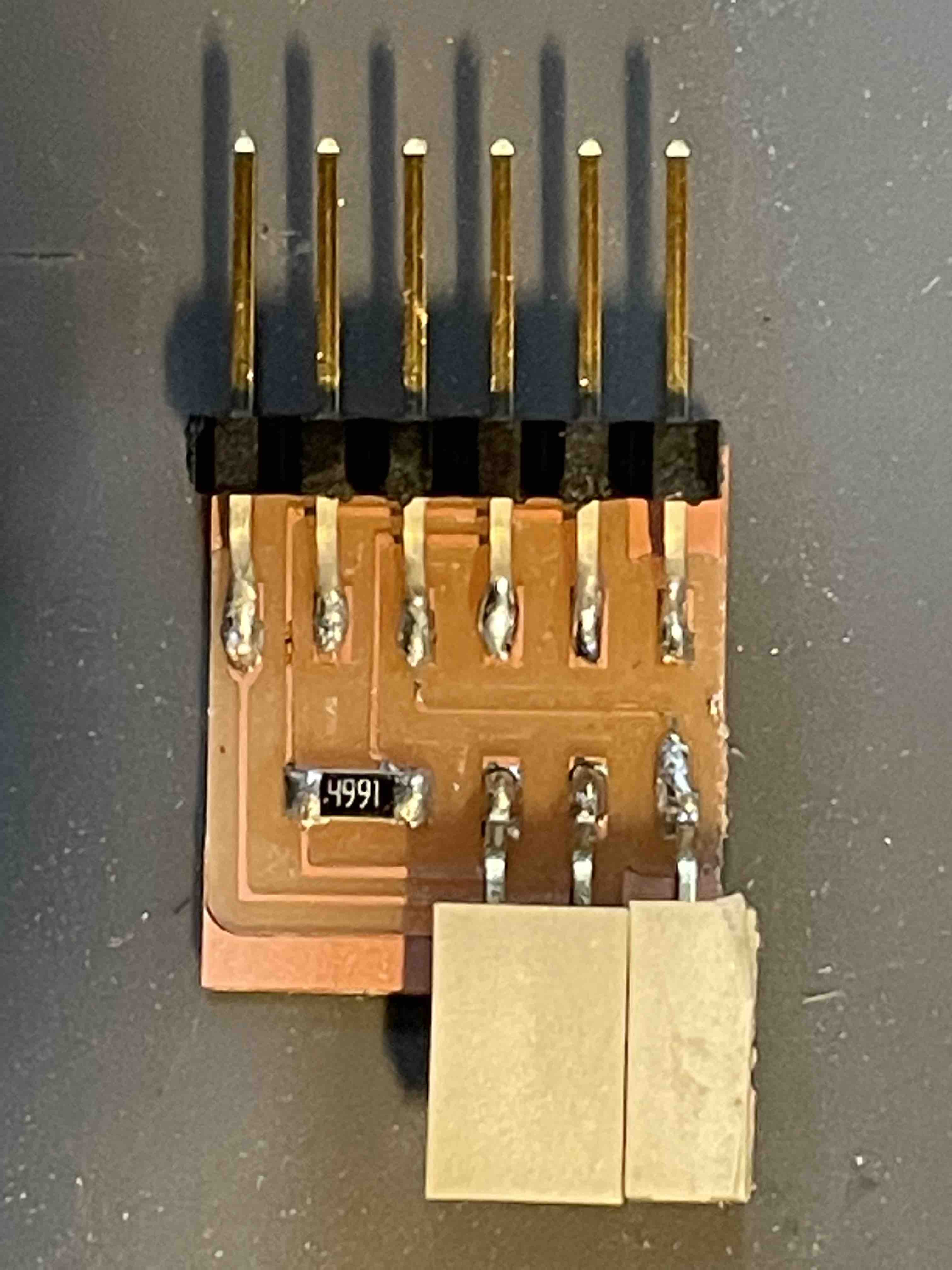
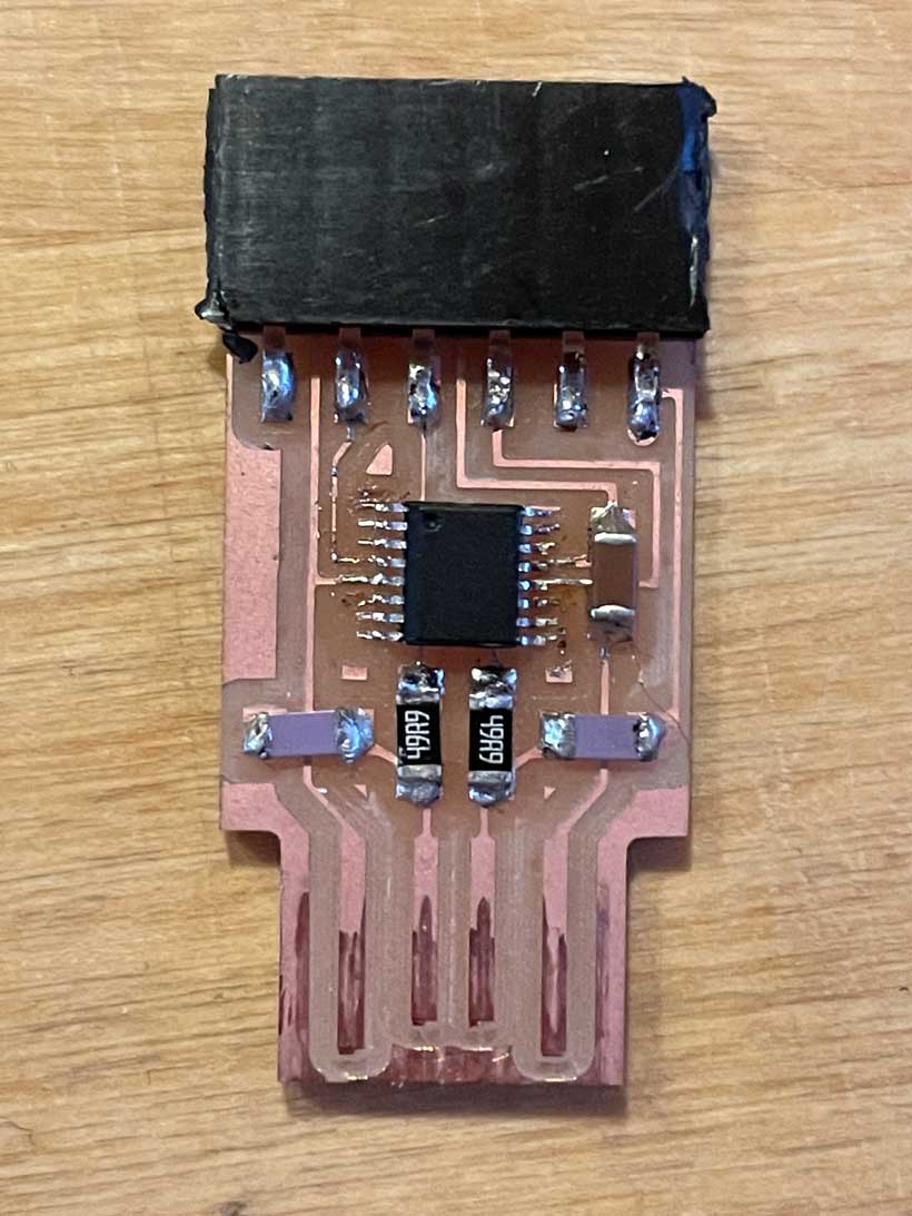
To make sure the FTDI board was functioning, I plugged it into a a computer, and .... tududu. It was detected. Music to my ears. Time to rest now.
III. Files
Z. Appendix
Assignment Files
Class Notes
Class Notes
Basic Electrnics
Bohr’s Model (of an Atom)
Voltage [V] (expressed in Volts) - Difference in charge between a positively and negatively charged area of a material.
Current [I] (expressed in Ampers) - rate of charge flow past a given point in an electric circuit.
Resistance [Omega] (expressed in ohms) - Measure of the opposition to current flow in a circuit.
Diodes restrict the flow of current to a single direction.
LED polarity (Longer leg = +)
V = I*R
Capacitance = C [expressed in Farrads (F)]
G-Code
Understanding Microcontrollers
Registers - Predetermined memory locations which store individual bits of a binary word (Use a series of flip-flops). In short, they are locations at which can be written to or read from.
Clock - Coordinates the speed at which controllers execute operations.
Binary - High1 Low2. **When selecting components that produce analog signals, must check that they produce a signal the controller can detect. ie: controller can read signals up to 5V >> Component cannot produce an amplitude above 5V.
ADC/DAC - Analog/Digital to Digital/Analog Converters
Abbreviations
CTs - Current Transformer
CTS - Clear To Send
RTS - Ready To Send
GND - Ground
VCC - Voltage Common Collector
RXD - Data Receiver
TXD - Data Transmitter
Recommendations
-
Update inventory when taking components.
-
Board internals cut with 1/64 end mill. Exterior with 1/32.
-
Make multiple small boards with definned functions rather than a single integrated board. If one fails, it is easier to replace/fix.
-
For the Microcontroller, reproducing an existing, documented board would prove to be more efficient than creating one from scratch.