7. Electronics design
- Group assignment http://fabacademy.org/2019/labs/lakazlab/assignments/week07/
- Use the test equipment in your lab to observe the operation of a microcontroller circuit board
- Individual assignment
- Redraw the echo hello-world board, add (at least) a button and LED (with current-limiting resistor), check the design rules, make it, test it.
- Extra credits: Simulate its operation. Render it.
Objectives
- [x] Shown your process using words/images/screenshots
- [x] Explained problems and how you fixed them, including how you worked with design rules for milling (DRC in EagleCad and KiCad)
- [x] Included original design files (Eagle, KiCad, Inkscape, .cad - whatever)
- [x] Screenshots and description of the process of redrawing the Hello board and adding the LED and the button.
- [x] Describe the process of creating the schematic and going to pcb design
- [x] Mention and link to fab libraries you used.
- [x] Mention design rules used for pcb design.
- [x] Describe the process of creating gerber les and using FlatCAM to generate G-code les.
- [x] Pictures of the milling process and soldering.
- [x] Describe any errors or problems with the board and how you fixed them. •
- [x] Describe the programming of the board.
- [x] Photos of your board.
- [x] Include all the files you created for download.
Electronics design week’s goal was to tweak an existing schematic by adding a led and a push button to it, the so called “Echo Hello World” board. The complete workflow from redesign, mill, solder and programming of the HelloWorld board had to be performed.
The Steps:
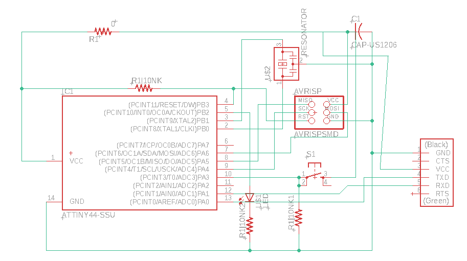
Recreate the schematic and add the led and push-button
Strategy for me was to try and create a ground rail around the design and a power rail through the middle as a baseline. Similar to the idea behind a breadboard Also i didnt want to pass more than one trace under the ATTiny chip (my personal choice). This strategy resulted in using an extra 0 ohm jumper to create a crossing otherwise impossible.
I designed the board in Eagle Cad and tried to perform the complete workflow therein.
Steps:
-
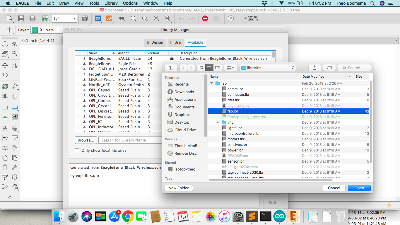
Download the Fablab library and place it into your eagle library directory. You could choose any folder location and set it in the Eagle >> Library >> Open Library Manager (Mac OSX)
-
Create new project >> Start new Schematic
-
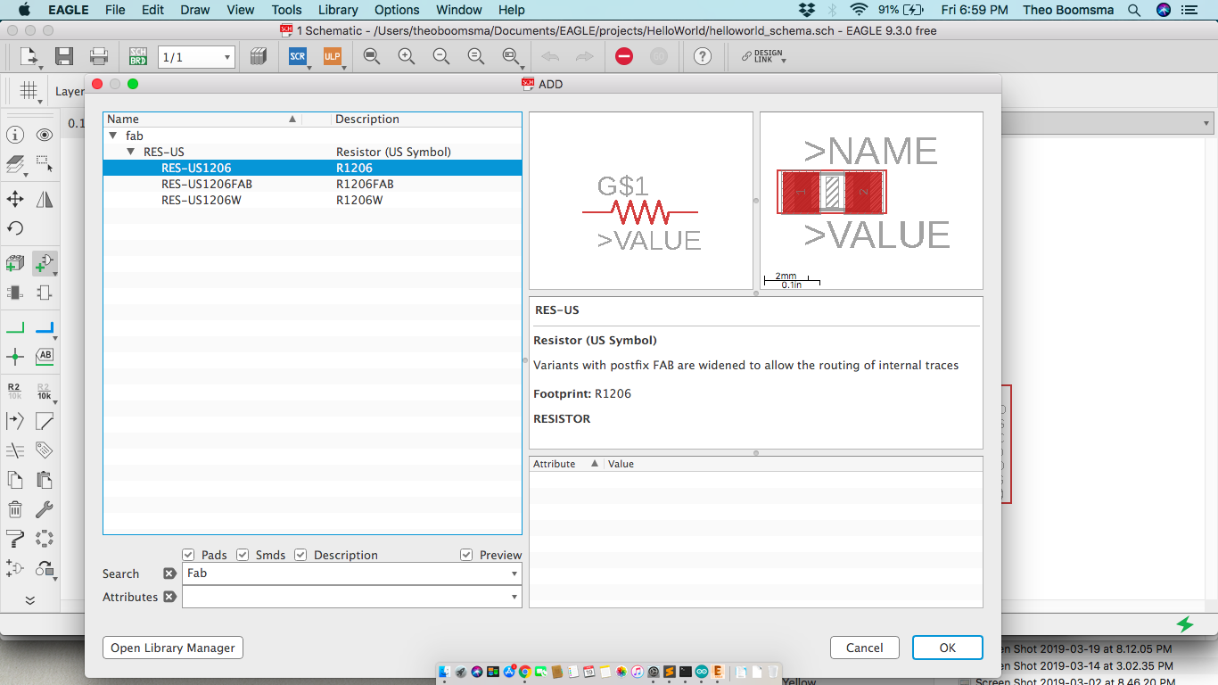
Add your desired components from the component library (filter on the Fab components)
-
Make your connections between components to finalize the schema
-
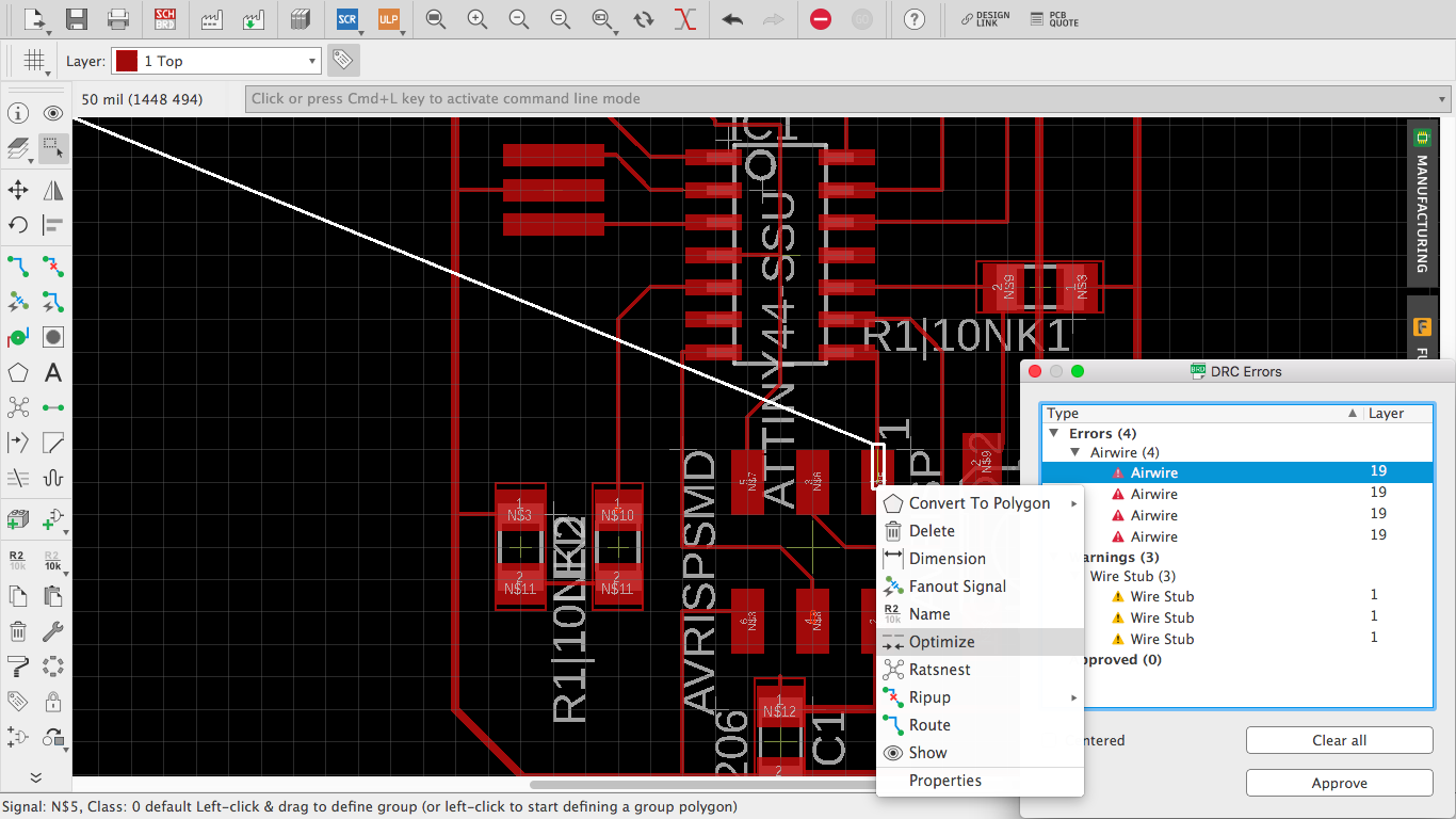
Switch over to the Board view File >> Switch to board , and now it’s time to create the best location en orientation for components and optimal routes for traces. Also here you add add labeling, border/frame, do manual/automatic routing. Finally doing the Design Rule Check one can be sure the board will be according to predefined set of rules. I just went with the standard rules and made the advised changes
- Stepcraft ULP for Eagle to Stepcraft NC code For exporting NC files directly from Eagle to Stepcraft mill i used this Stepcraft ULP that automates this process. Generated the gerber files from it that could be loaded into WinPCNC
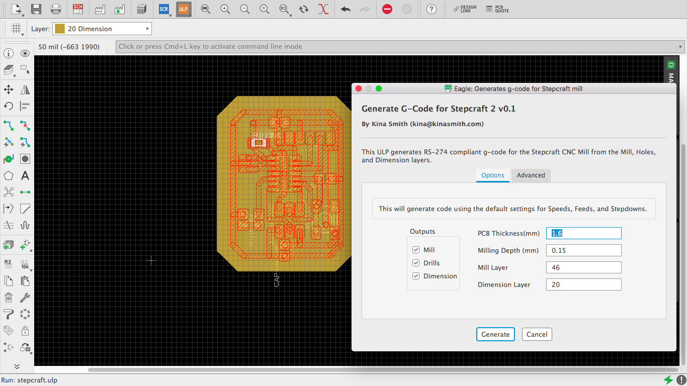
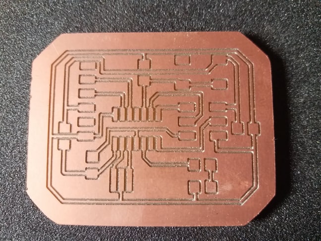
Mill and solder the PCB
Since our mill does not have tool changer to switch mills and loses XYZ zero every now and then i made added extra margin around the routes for the Dimension Layer. Actually it looks nicer this way too ;)
The PCB board had to be re-designed based on the additions using your own strategy and creativity
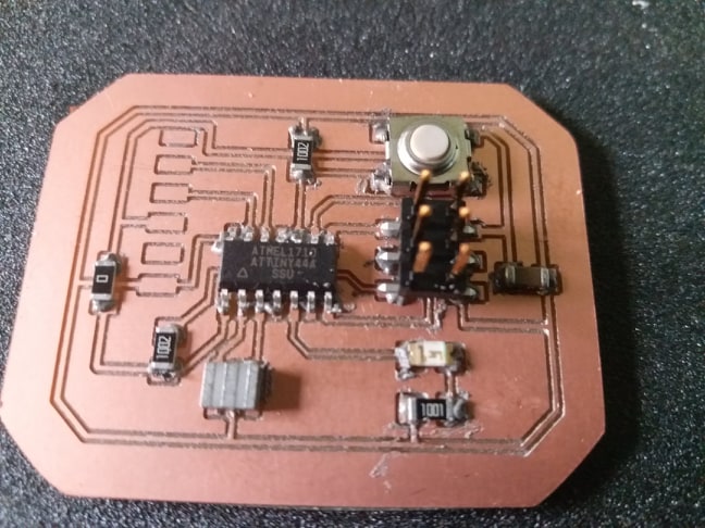
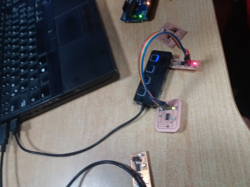
Inspect & Test the board
After optical inspection of the traces and the solderings i went on to measure with a multimeter for:
- Short circuits (measure between and V+ and GND)
- Reference voltages (Measure known voltages at v+ of the USB, MCU)
- Response of the switch actions (correct switching)
Programming the board
Program the HelloWorld board with Arduino IDE connected to via our FabISP board we build from week 5.
Added a simple blink script from Arduino IDE.
Before programming select the ATTiny44 board and Processor and ofcourse the USBTiny.USB as the programmer.
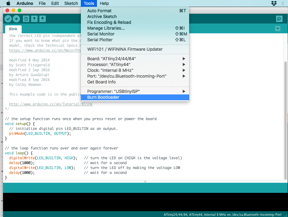
Upload the sketch and watch the miracle of a blinking led dawn upon the daylight!
Files
Week7.zip files containing Eagle Files & NC files
Links & References
Design & Layout PCB tips https://www.allaboutcircuits.com/technical-articles/easier-pcb-design-eagle-cad-tips-and-tricks-part-3/
https://learn.sparkfun.com/tutorials/using-eagle-board-layout/all
Eagle Layer definitions https://www.lucidar.me/en/eagle/understanding-layers/