Computer Aided Design
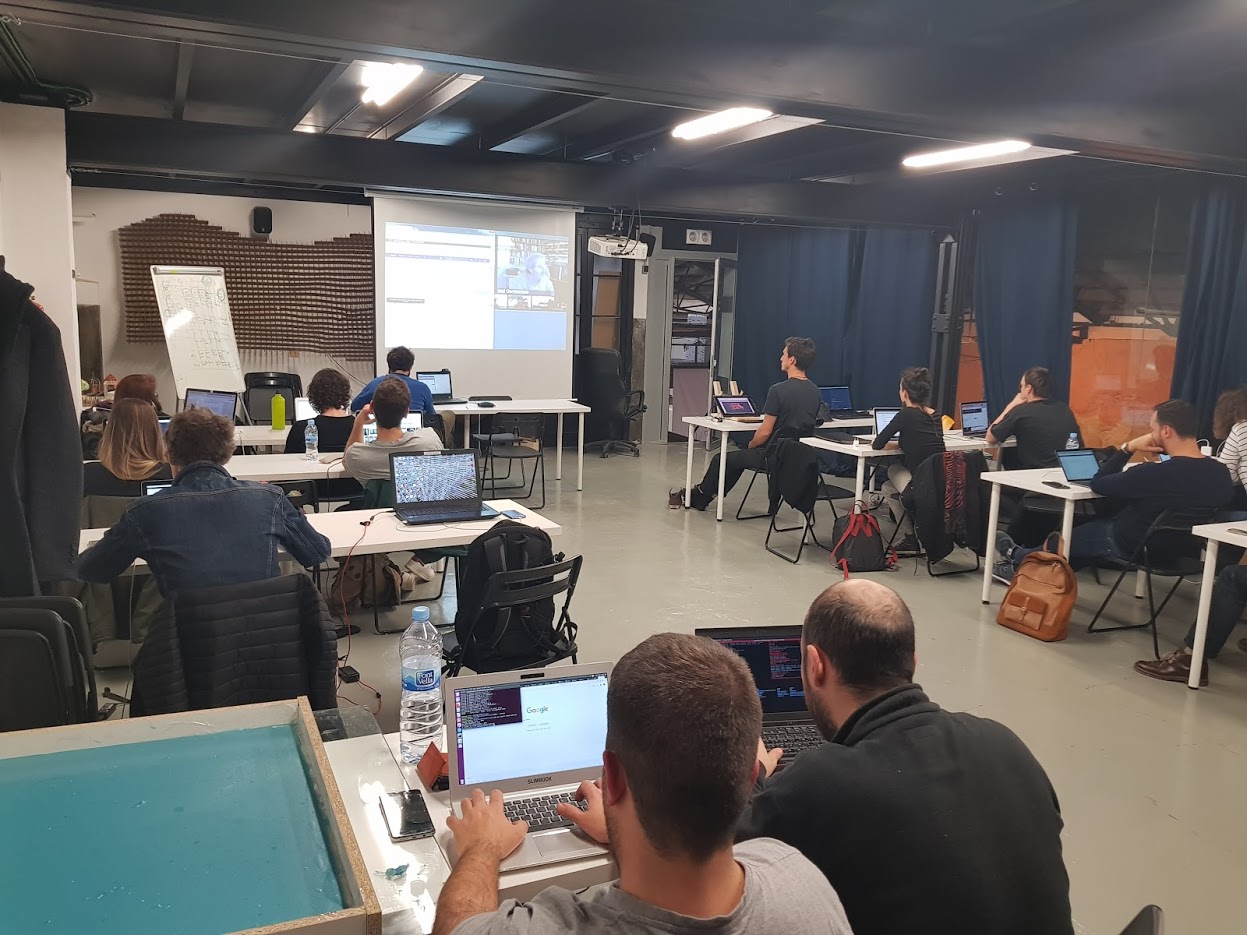
Week 3 - Computer Aided Design
Here you will find my work description during this third week
Class notes
Assignment
Our assignment for this week is: model (raster, vector, 2D, 3D, render, animate, simulate, …) a possible final project, and post it on your class page
I am going to create simple parts in many software to compare them. The part is one of my final project part. It consist in a ring slots to put magnet.
But first in order to user web compatible screenshots I want to user imagemagic to convert file in lightweight format.
Undex ubuntu subsystem I install image maging using following command line.
sudo apt install imagemagick
going to screenshots subfolder and do some tests
cd assets\images\classes\03
Original drawing.png file 68ko 1288x910px
convert drawing.png -resize 1000 -qualty 75 drawing2.png
Result is 110ko and 1000x707px ?! Try to use other arguments
convert drawing.png -resize 1000 -quality 50 PNG8:drawing2.png
Result is 23ko and 1000x707px ! Great
according to this source we can use mogrigy to batch process files (Mogrify is a mainly used for batch processing, which means you want to modify existing files in batch mode)
so I type (after backuping images)
mogrify *.png -resize 1000 -quality 50
but nothing happened
mogrify -resize 1000 -quality 50 *.png
was better but not satisfying yet
mogrify -format PNG8 -resize 1000 -quality 50 *.png
Result is almost ok but extension is now .PNG8
mogrify -define png:color-type=3 -resize 1000 -quality 50 *.png
Annnnnd … everyting is gone :(, hopefully I made a backup
mogrify -format PNG -resize 1000 -quality 50 *.png
is not optimal but I cannot do better right now
20180205 Edit I create a simple bash script to convert all files in a directory (using for loop)
Introduction
The only CAD software I am confortable with is Sketchup but I am here to study more.
2D CAD Sofwares
QCAD / Libre CAD
Download LibreCAD - (QCAD fork - tottaly free)
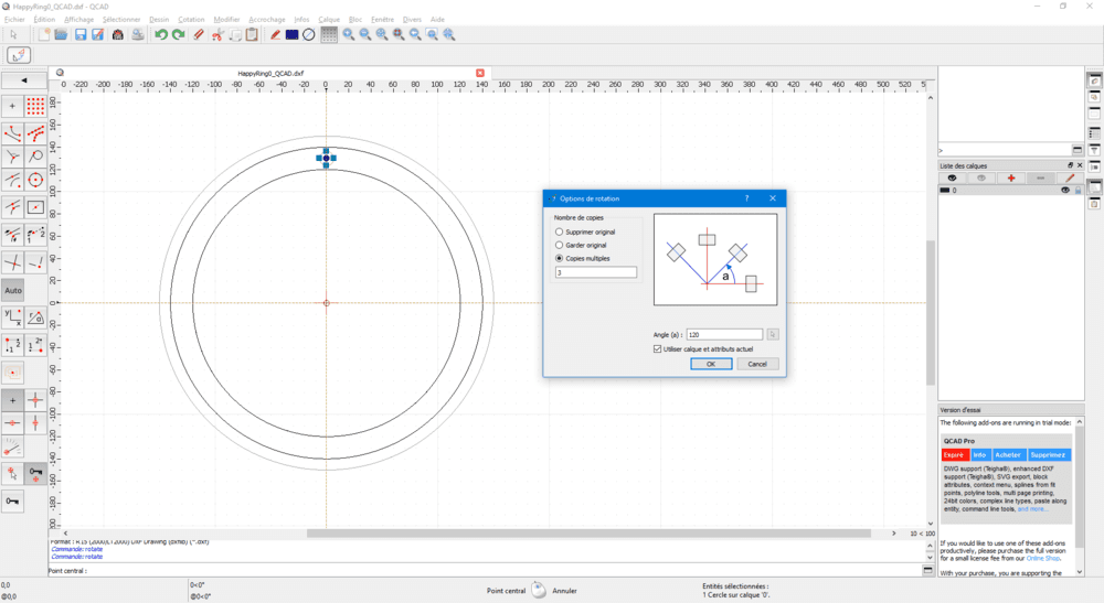
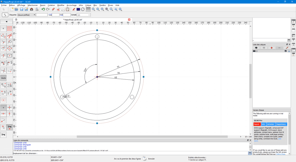
I spent a few time trying to draw a sketch of a simple ring on QCAD / LibreCAD, here are some shots of it.
For this test I used QCAD that I already have installed on my computer but I assume LibreCAD work the same way.
I am not yet confortable with this software but I want to give a try and I know this is a powerfull software but unfortunately not realy parametric. However we could run some script using javascript and a dedicated API (not experienced yet).
I usually use sketchup even for 2D CAD design because of its simplicity. QCAD propose a lot of feature and I should spend more time discovering them. But now for the “simple” test, I was looking for simple commands like drawing circle, rotations, circular pattern. It was not really intuitive because I was looking for command in this jungle of feature. But with a little help from the documention, I finally manage to do my “simple” drawing.
3D CAD Sofwares
OnShape
To use online go to OnShape web page
I just want to test OnShape first because I heard a lot of fabmanagers say it’s an easy to use software, so that is the occasion to give a try.
So I log in using information received by email from fab academy coodination.
I decided to create a simple ring with slot on top and on bottom
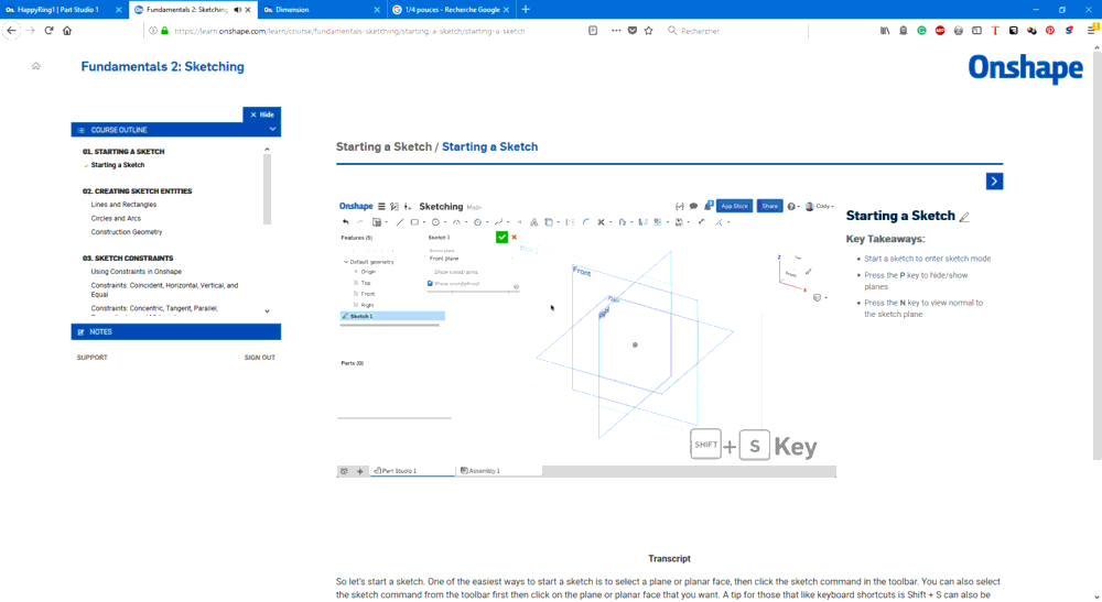
I created a sketch, draw a circle on the XY (Top) plan
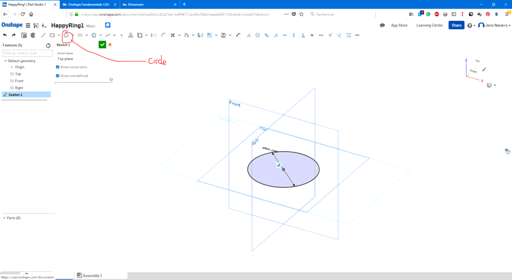
But I didn’t find how to set the diameter, so I decided to take a tour on the tutorial pages.
I found the distance tool that allowed me to set the circle diameter.
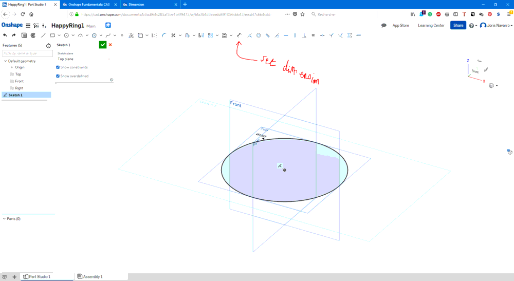
to create the ring I draw another circle but using the offet tool
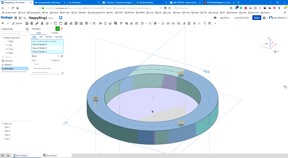
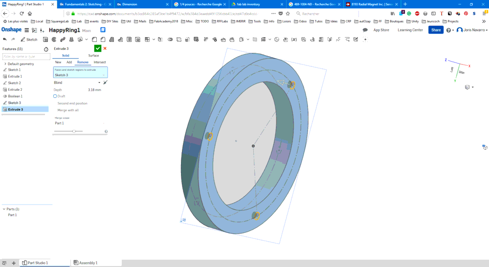
I validated the sketch then I extrude it in order to create a solid

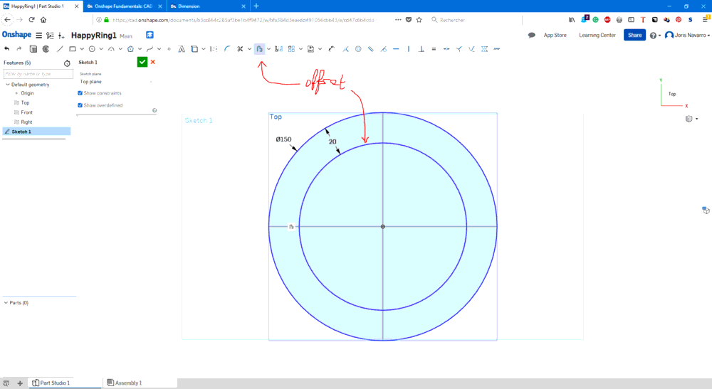
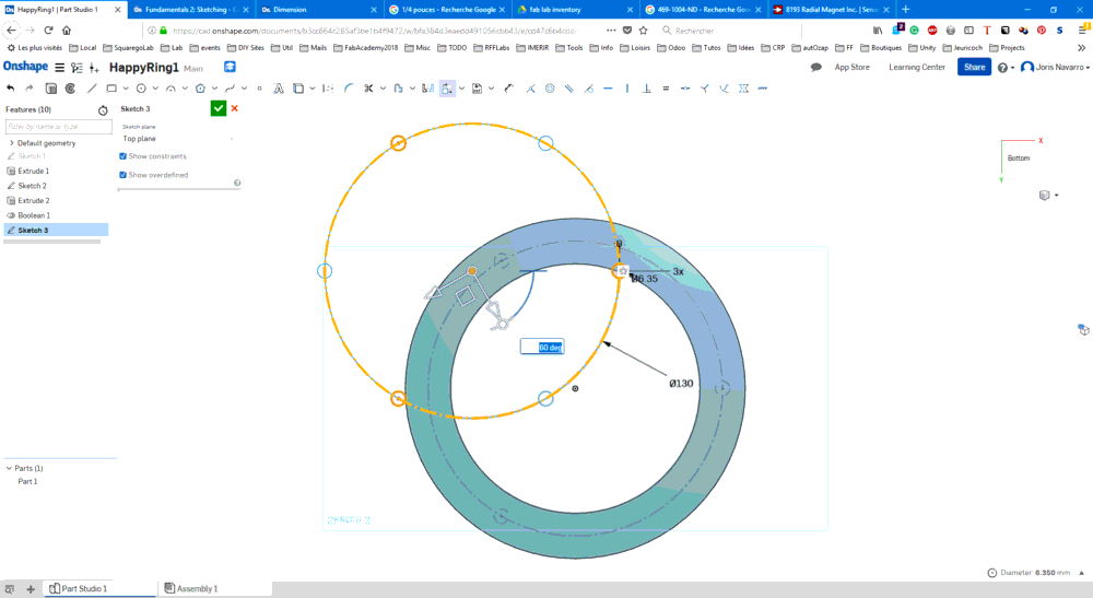
On the top surface I drew a circle using the offset -10mm and set it as a construction geometry. That helped me drawing a smallest circle that will become the slot. I used the circular pattern operation to create 2 other circles.
Then I extruded these 3 circles into the solid and I applied a boolean (substraction) operation.
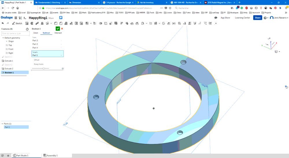
Ok for the top suface of the ring, let’s see if we can do the same for the bottom.
I tried to copy/paste the secind sketch into the tird one, but it was not aligned. So I moved it and rotate it to 60 degrees
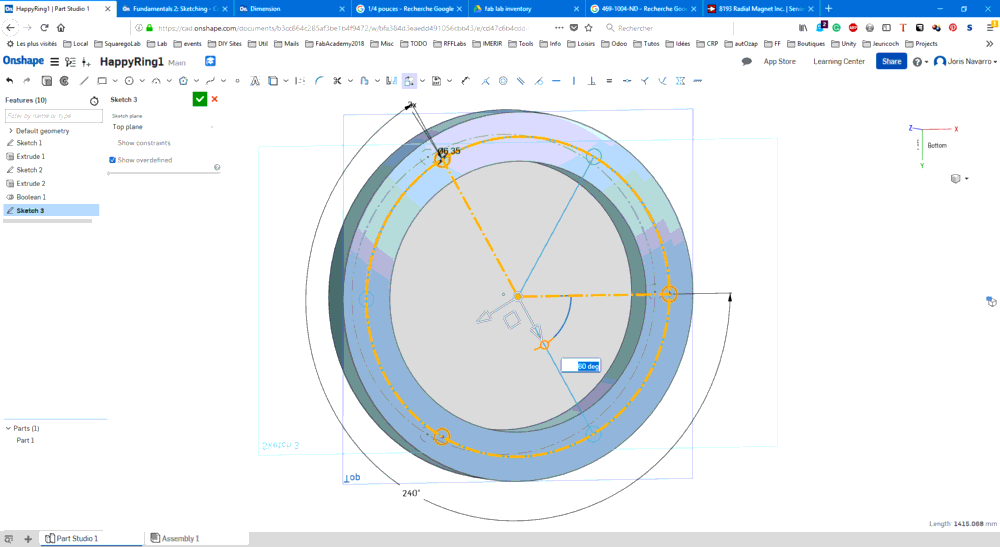
I extruded the new skecth I substract the result.
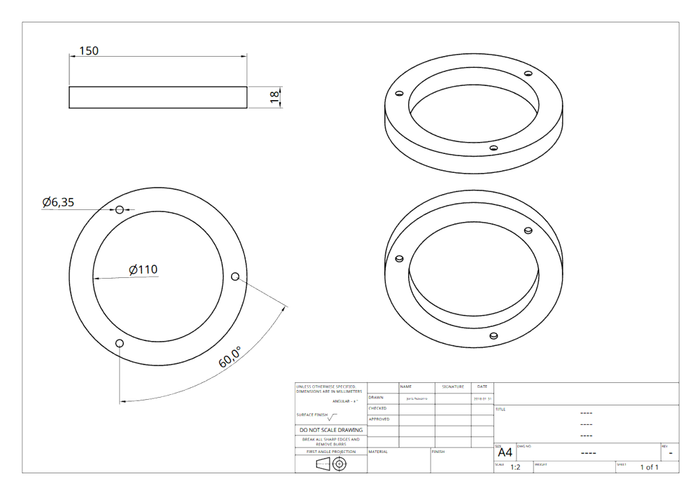
For testing purpose I tried exporting the part as STL and I generated a drawing as ISO A4 pdf.
Here is onShape export as a parasolid document
Link to the document on OnShape plateform
Autodesk Fusion 360
Go to autodesk fusion360 web site (academic version), Create account, download and run to start designing.
After registering to autodesk platform I downloaded Fursion 360 and run it. I have a 30 days trial licence.
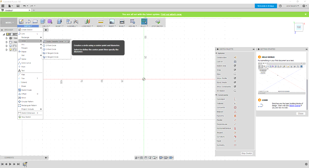
I follow the tutorial about sketches.
This part is slightly different becaus I added an inner extrusion in the ring.
I repeat sketches and extrusion to do the same part.
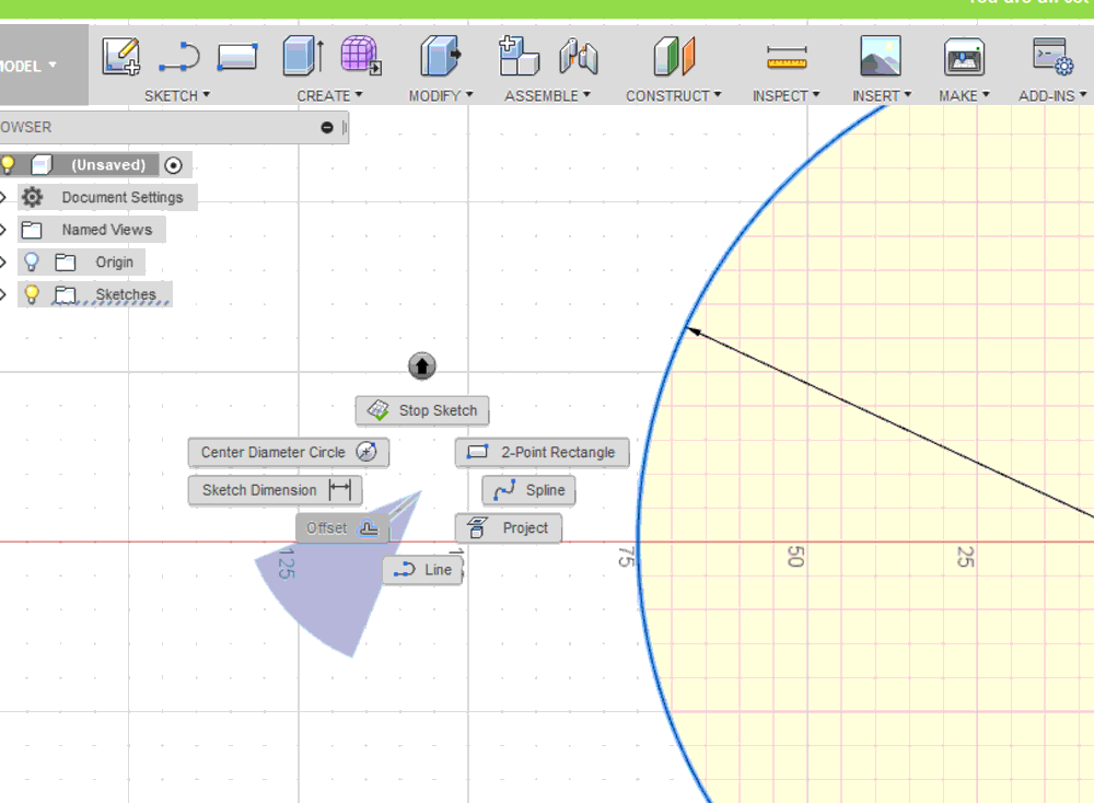
First I drew a 150 mm diameter circle on the XY plan.
Then I defined 20mm offset using right click command access.
I extruded a 18mm to create a body.
I drew an new circle on a new sketch and used the circular pattern (thanks Santi I did not find the command) to repeat it 3 times over the ring.
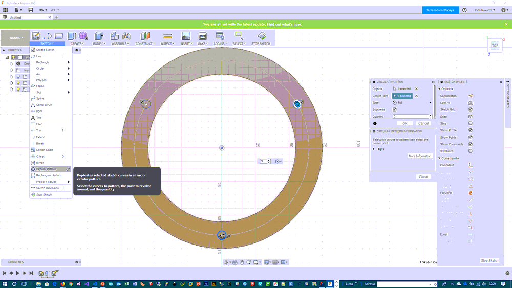
I extruded this sketch to create the slots.
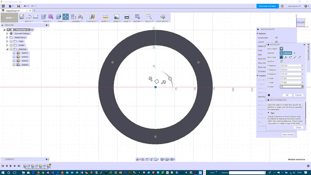
The hard part was to copy this sketch to a new one on the bottom plane. The way I used was to copy/paste sketch entities and move -18mm on z-axis and rotate (60 degree) using the ring center as pivot.
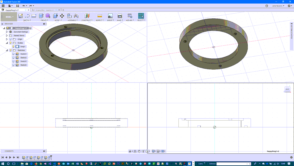
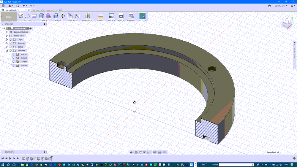
I added an extra sketch and extrusion to creat thin inner XXX
Finally the part looed like that.
For testing purpose I tried exporting the part as drawing as ISO A4 pdf.
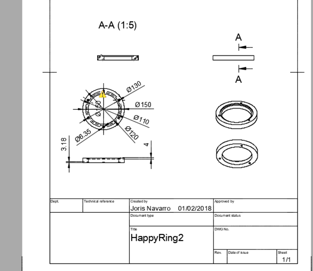
FreeCAD
download free cad from official web site, install it and run the software.
I never used FreeCAD before, and I feel confortable. Maybe because I used the previous CAD softwares just before. Sketching and extruding was not so difficult for a basic part. I played with plans, symetries and basic operations with ease. The only point I did’nt get how to assemble. I read that there is a special plugin for that but I did’nt explore that possibility.
Here are some screenchots of the design process used.
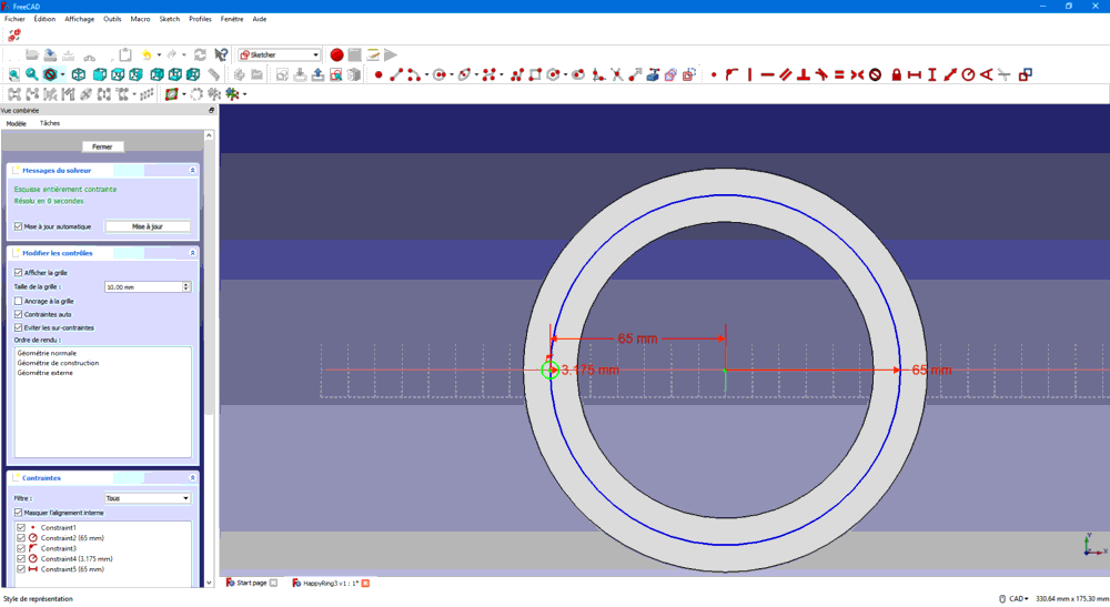
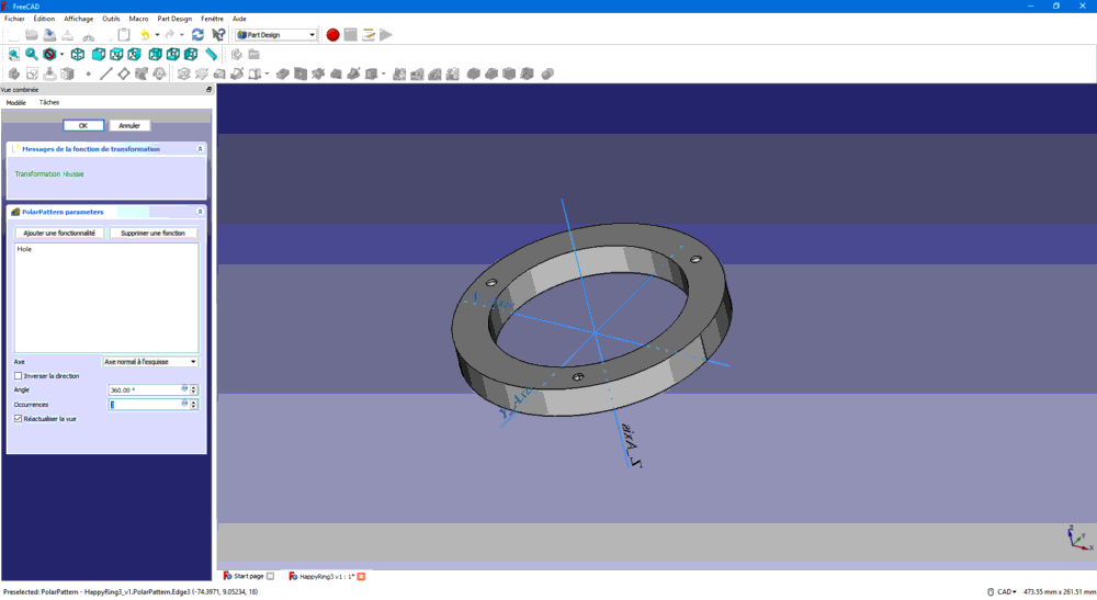
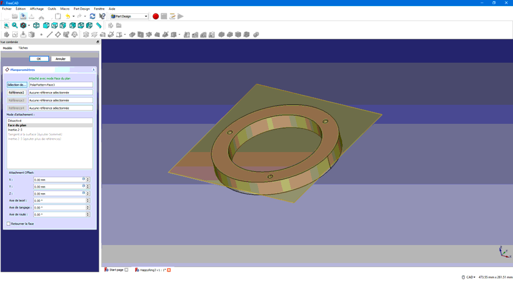
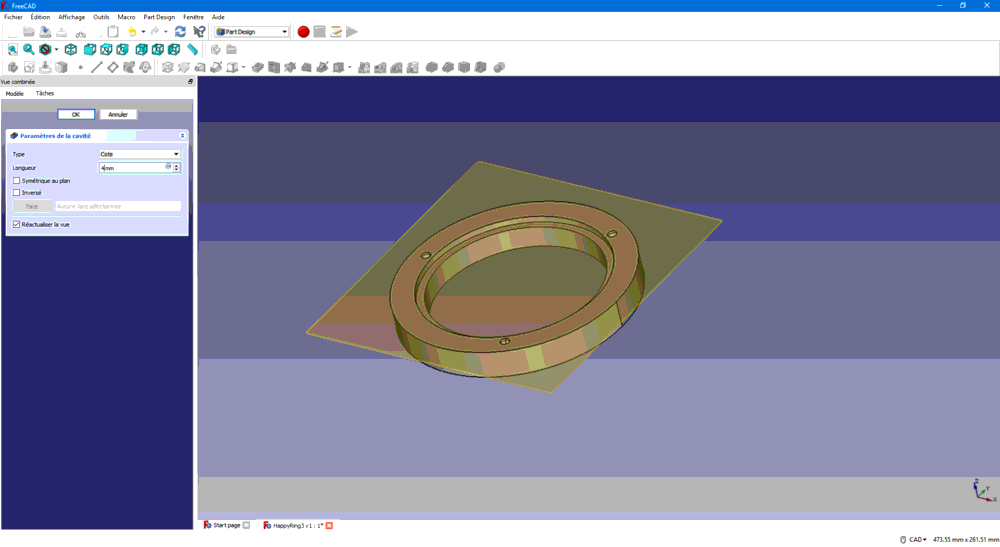
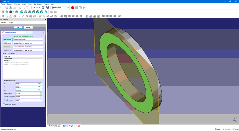
Here is the freecad file : HappyRing3
Solidworks
We recieved an email from fabacademy coordination team the process to download an education version of solidworks.
** Solidworks Expert Tip: ** In the assembly, when you import a component drag ** but do not drop ** component in the main panel, this could fix its origin, when you see the preview just click the yellow tick. So the origin of the component will be the origin of the assembly.
ferdi@fablabbcn.org
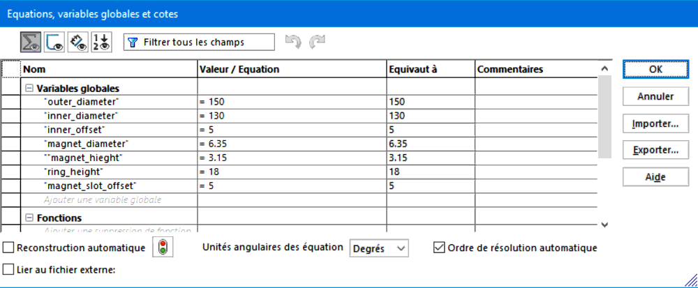
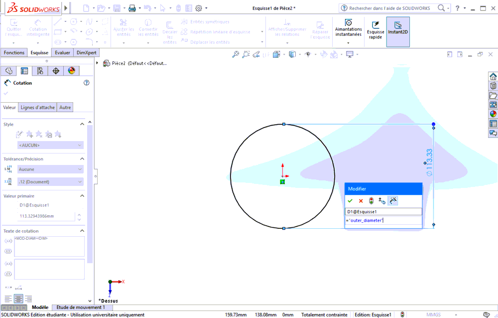
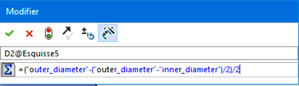
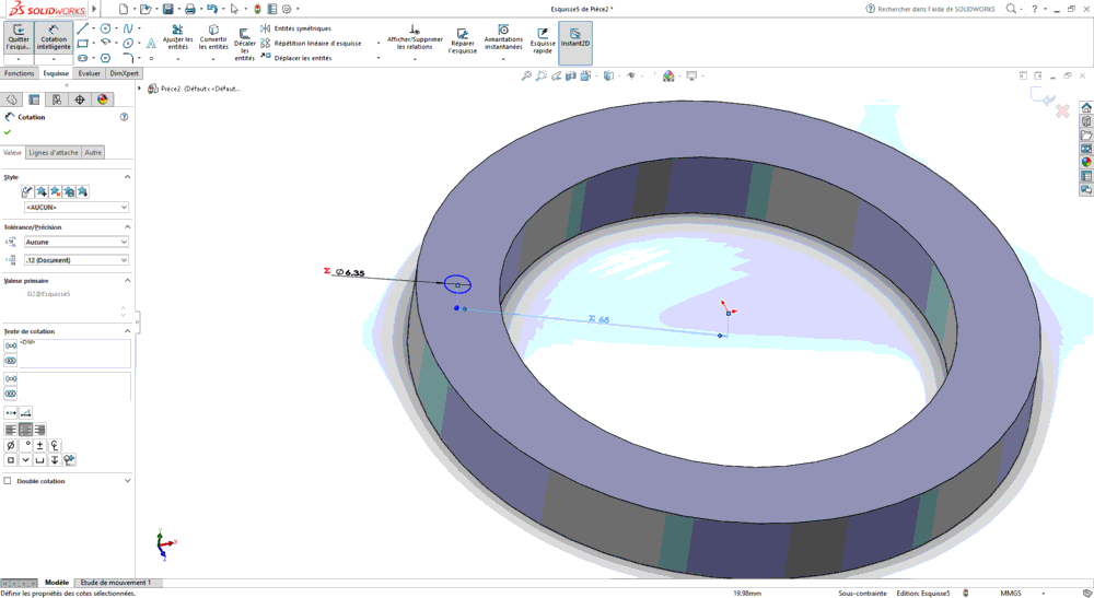
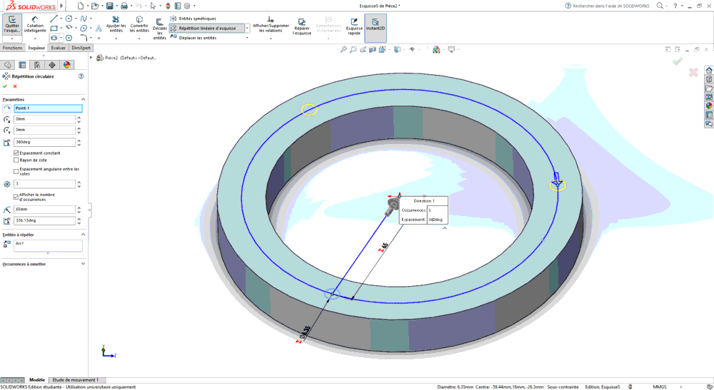
I decided to uses equations to create a parametric design Using equations
Defining variables. The sketching and apply some basing operations like extrusion, chamfer, circular pattern. My experience is taht this software is really convenient when your set all constraints, it is not flexible? I means it is easy to be in a mess besause of unplanned reations due to unset constraints.
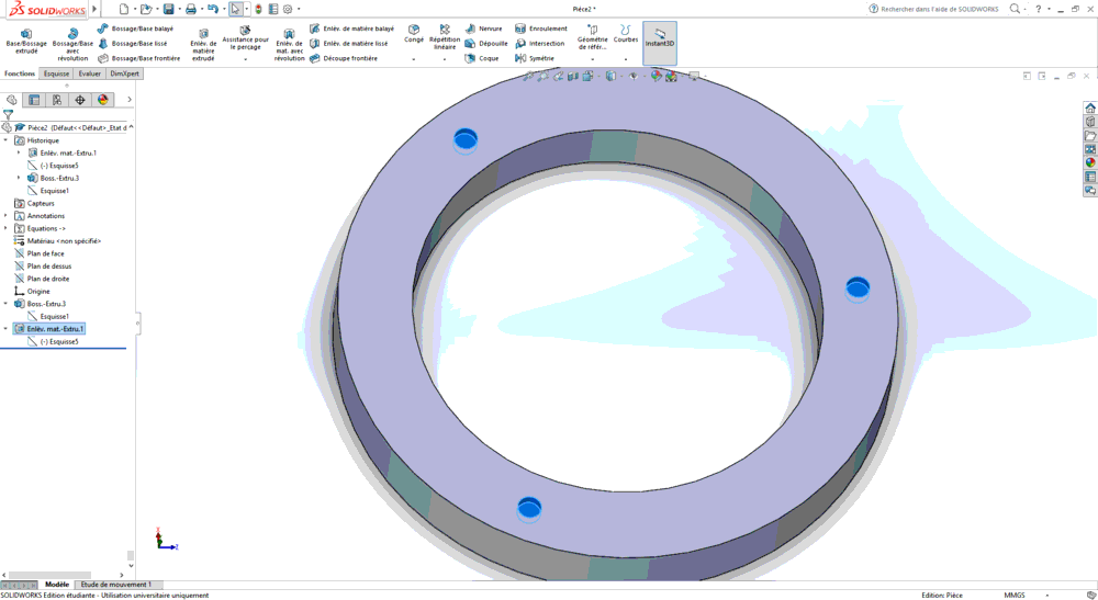
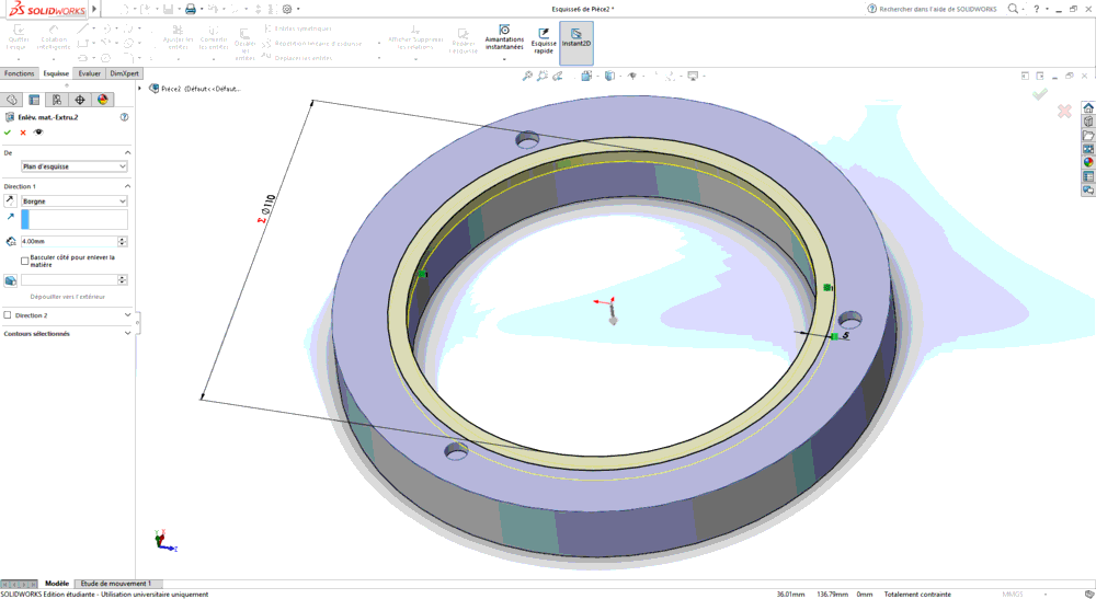
Here is the solid work file : HappyRing4
Rhinoceros 3D
Get Rhino from offcial website, you will have a free 90 days licence.
@santifu made me a quick demo of my part using Rhinoceros 3D
So I tried to redo what he did, using what I saw.
Draw sketches
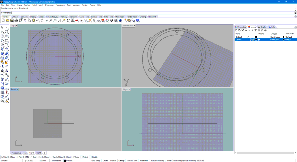
and creates solids using Extrude curved sufaces
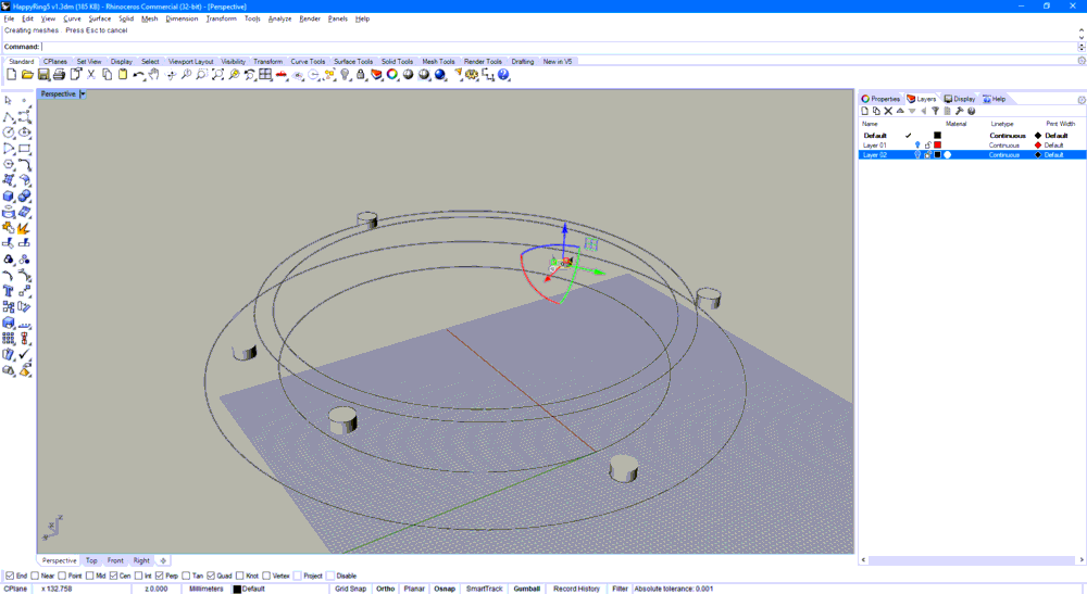
Do a boolean sustract operation
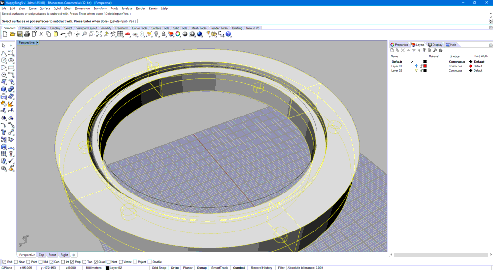
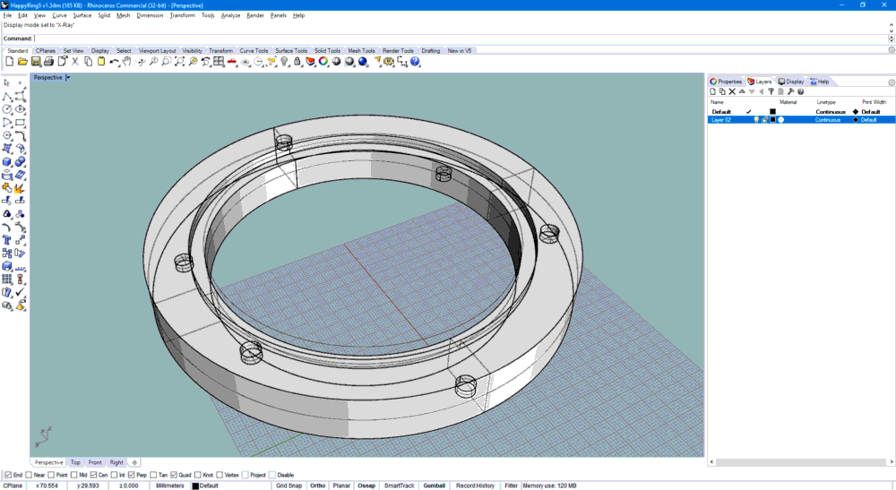
Here you can find the file produced
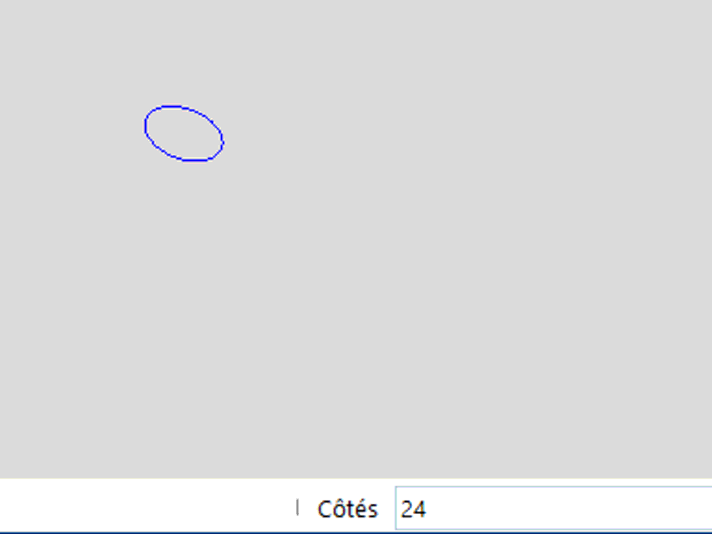
Sketchup
get Sketchup for free, free 30 days of Pro features.
Since a few monthes Trimble propose a web version of sketchup that is also nice.
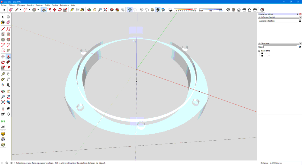
I am conforatble with this tool, so I took me 5 minutes to do the same part.
To avoid bad looking circle, don’t forget to set numbers of sides
Use offset tool
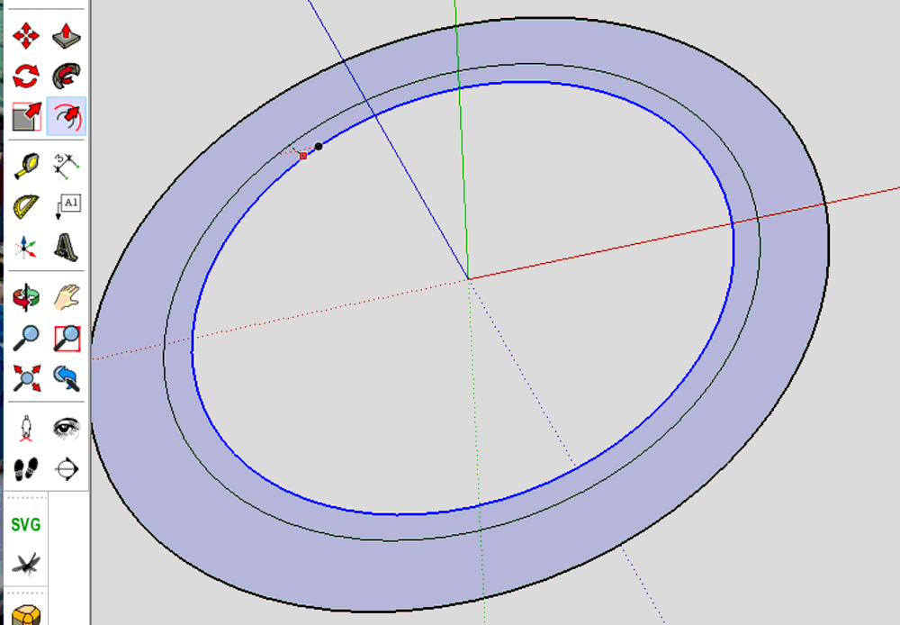
Duplicate circle using rotation (using Ctrl key)
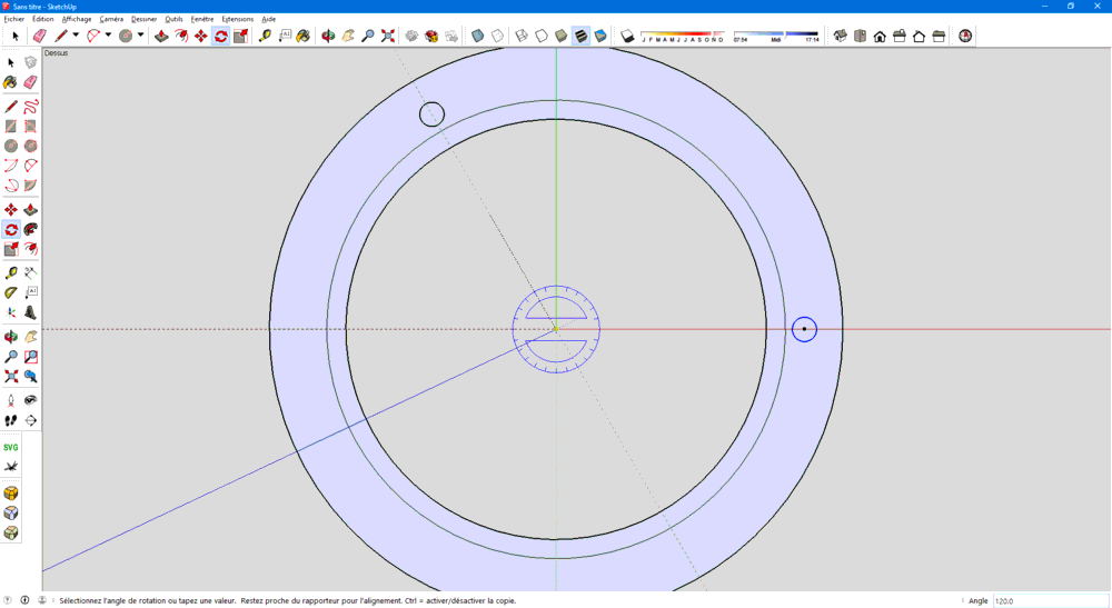
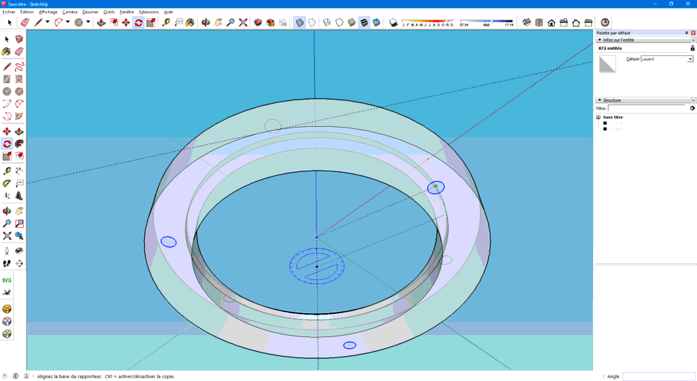
here is the result
Antimony
Matt Keeter Antimony project web page
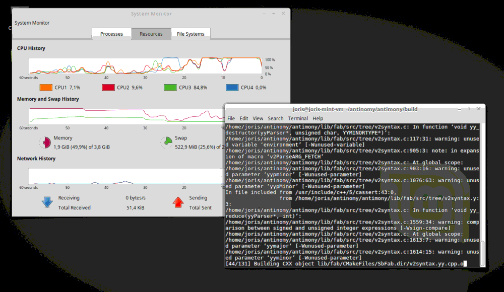
In a custom, fresh Linux Mint virtual machine, I installed sources of Antimony using provided commands
Install dependencies
Not written but don’t forget to update package lists
sudo apt update
sudo apt install git build-essential libpng-dev python3-dev libboost-all-dev libgl1-mesa-dev lemon flex qt5-default ninja-build cmake
git clone https://github.com/mkeeter/antimony
cd antimony
mkdir build
cd build
Build and launch the application
cmake -GNinja ..
** Issue found (TODO: submit issue) **
Build failed :
sudo apt install libqt5opengl5-dev
fixed my problem
cmake -GNinja ..
Build OK
ninja
And you can go take one (or more) cofee => VM Freezed :(
Allow more memory, but this could take a while
./app/antimony
I run sudo ninja install to install antinomy in my path
Then I can play with it
The part is quite simple, just use difference of cylenders
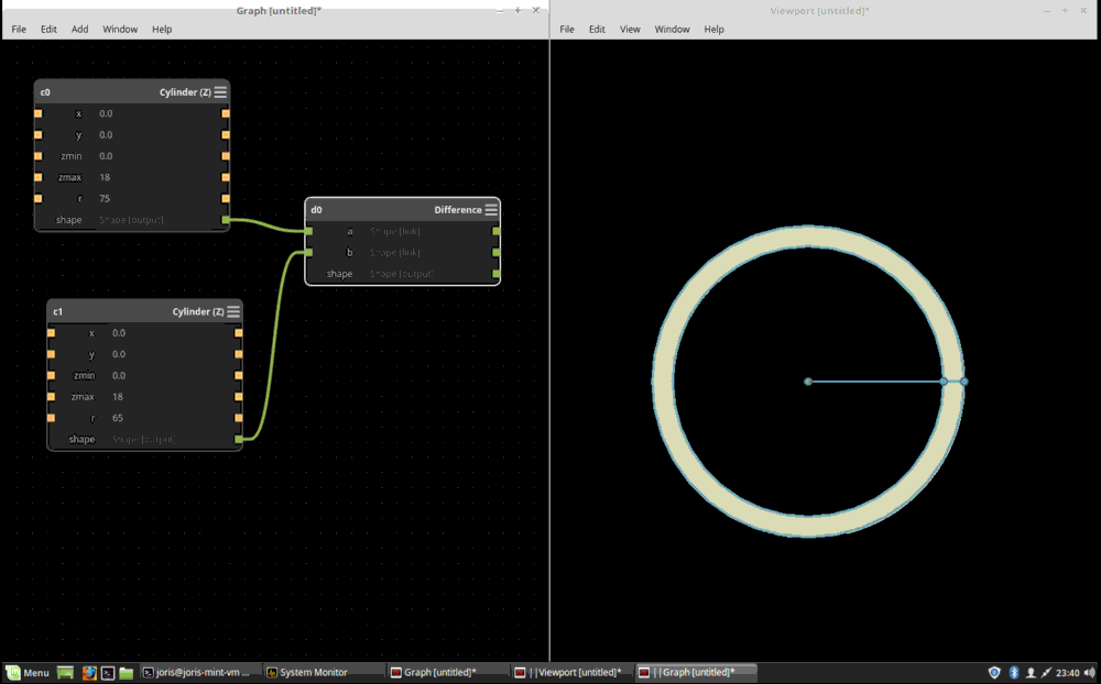
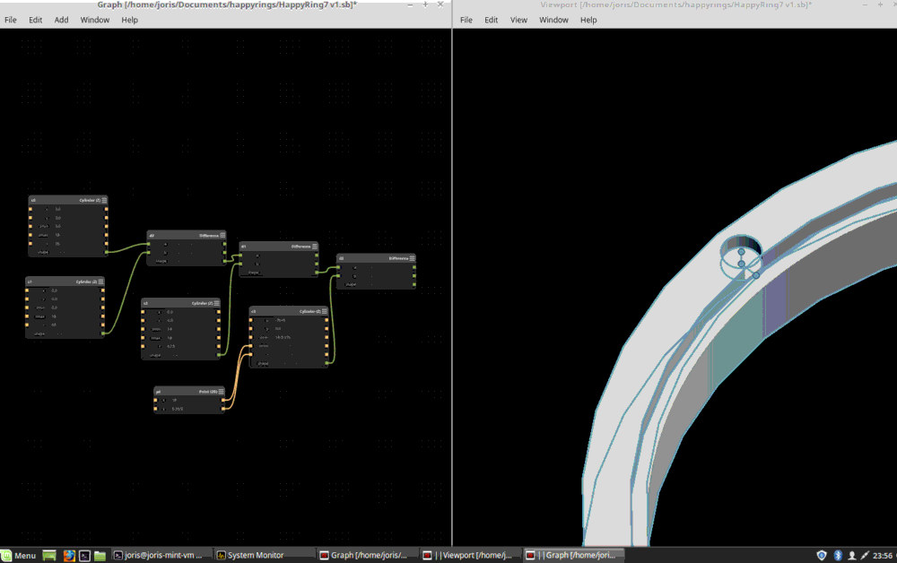
Here is the file : HappyRing7
Openscad
get Openscad software from official web page
OpenScad is a scripting modeling tool. The model is simple and consist of substracting cylinders.
Here is the code:
// resolution
$fn = 50;

// Parameters
inner_radius = 120;
thickness = 30;
outer_radius = inner_radius + thickness;
height = 18;
padding = 0;
magnet_width=6.35;
magnet_height=3.17;

module ring(inner_radius, thickness, height) {
    difference() {
        // This piece will be created:
        cylinder(r=inner_radius + thickness, h=height, center=false);

        // Everything else listed will be taken away:
        cylinder(r=inner_radius, h=height, center=false);
    }
}

difference() {

    ring(inner_radius,thickness,height);

    translate([0,0,height-5]) {
       ring(inner_radius+20,10,5);
    }

    translate([0,0,0]) {
       ring(inner_radius,20,5);
    }

    translate([inner_radius+10,0,height-magnet_height]) {
        cylinder(r=magnet_width, h=magnet_height, center=false);
    }

    rotate([0,0,120]) {
        translate([inner_radius+10,0,height-magnet_height]) {
            cylinder(r=magnet_width, h=magnet_height, center=false);
        }
    }

    rotate([0,0,240]) {
        translate([inner_radius+10,0,height-magnet_height]) {
            cylinder(r=magnet_width, h=magnet_height, center=false);
        }
    }

    //bottom holes
    rotate([0,0,60]) {
        translate([inner_radius+10,0,5]) {
            cylinder(r=magnet_width, h=magnet_height, center=false);
        }
    }

    rotate([0,0,180]) {
        translate([inner_radius+10,0,5]) {
            cylinder(r=magnet_width, h=magnet_height, center=false);
        }
    }

    rotate([0,0,300]) {
        translate([inner_radius+10,0,5]) {
            cylinder(r=magnet_width, h=magnet_height, center=false);
        }
    }
}
And here is the result
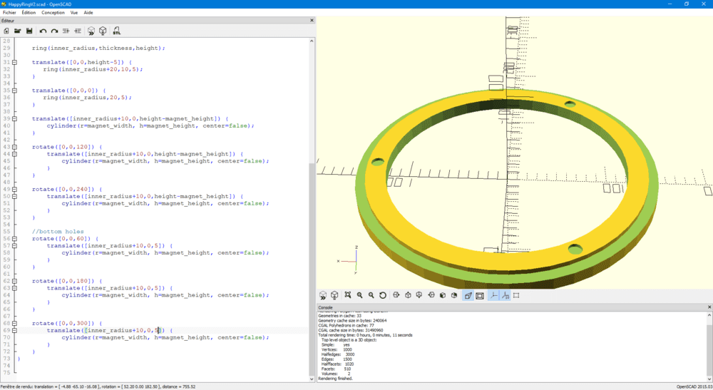
Download the file : HappyRing8
Conclusion
My feelings are that thoses Tested CAD Softwares are very powerfull but should not be used for the same goal
-
FreeCAD : is not so easy to enter but looks powerfull, assembly is missing
-
Rhino : Can do everything exceot parametric (will try grasshopper later)
-
Fusion 360 : Easy to use, but on some case shows its limits. It has CAM module, that will be very usefull
-
Solidworks : Do what is made for, powerfull but easy stuff could be difficult (copy paste of sketch in different plan), ideal for mechanical designs
-
OnShape : First to be tried, and fantastic, collaborative, maybe limited on assemblies, I would say I recommand it for hobby projects
-
Sketup : Great for simple sketches, fast and easy to use, I recommand for simple projects
-
Antimony : I love this, but I need more time to explore more possibilities
-
openscad : easy to use for simple parts
If I try to compare them
| Tables | - Usability | - Accessibility | - Potential | - Total |
|---|---|---|---|---|
| FreeCAD | 2 | 5 | 3 | 10 |
| Rhino | 3 | 2 | 4 | 9 |
| Fusion 360 | 4 | 3 | 4 | 11 |
| Solidworks | 4 | 1 | 4 | 9 |
| OnShape | 4 | 4 | 4 | 12 |
| Sketchup | 4 | 4 | 3 | 11 |
| Antimony | 3 | 3 | 3 | 9 |
| OpenScad | 3 | 4 | 2 | 9 |
I cannot decide wich one I will use to design my whole final project, because I want it open source for every one to make their own, so I think I have to discard the pay ones (Solidworks, Rhino). OnShape is very user-friendly and free solution for opensource projects but we don’t know if it will remains free, and your files have to be hosted on their cloud. FUsion is Free for is actually free for startups and hobbyist but will it remains ?
I feel like I am loking for something parametric in order to propose highly custumizable product. I would like to use a Command line interface (CLI).
The complexity of my project is not focused on design parts, not particular assembly.
As I use a proper Common Hardware Interface, I will probably work with several CAD softwares, exploiting each of them for their advantages (parametric, hierarchical).
Stay in touch
Hi, I'm
Joris Navarro, from Perpignan (France), a proud dad, a fab director/manager, a teacher, a ceo, a FabAcademy student, but not only. Click here to know more about me.
Check my work for FabAcademy on FabCloud GitLab
@joris.navarro.
Want to say Hi ? Please send me a message.