Menu
HomePrinciples and Practices
Project Management
Computer-aided Design
Computer-controlled Cutting
Electronics Production
3D Scanning and Printing
Electronics Design
Computer-controlled Machining
Embedded Programming
Molding and Casting
Input Devices
Output Devices
Interface and Application Programming
Networking and Communications
Mechanical Design
Machine Design
Wildcard
Applications and Implications
Invention, Intellectual Property, and Income
Project Development
Final Project
Week 7
Electronics Design
Week Assessment :
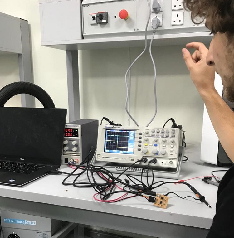
use the test equipment in your lab to observe the operation of a microcontroller circuit board.
redraw the echo hello-world board, add (at least) a button and LED (with current-limiting resistor)
check the design rules, make it, and test it.
extra credit: simulate its operation extra credit: render it.
Previously I used Multisim for designing a circuit. still, I'm a beginner on designing circuit but the good thing is that I have some background. Anyway, we had a session about the electronic components and their symbols. Wendy gave us a list of the component which is made by Nadya Peek.
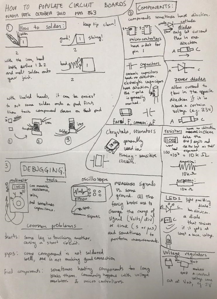
Then we discuss the use of each component with the help of captain Carl. Then I download the KiCad. KiCad is an open source software. European Organization for Nuclear Research (CERN) has already contributed greatly to KiCad. read more about KiCad licenses After I finished installing KiCad I download the library for the tutorial. I found this link that shows how to add a library in KiCad I faced difficulty to insert Fab library each time I opened the KiCad I had to add Fab library. I spend one day with Wendy trying to fix this issue till I finally decided to move to Eagle.
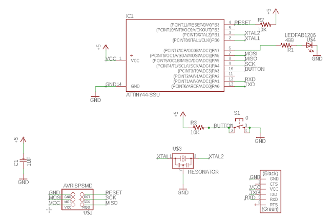
Eidha showed me how I use eagle and how to connect lines by labeling and how to add components.This is my schematic. I didn't design this board I take the design from the tutorial. My background in electronics helps me to understand why they use this component. In this board, I only add LED and two resistors and pushbutton. One of the resistor I connected to LED to protected from burning and to limit the current that goes into LED. While the second resistor connected to the pushbutton and they called pull up resistor we use it to prevent accidental switching of digital circuits, any unconnected inputs called “floating inputs” should be tied to a logic “1” or logic “0” as appropriate for the circuit. Later on I found this great SparkFun tutorial how to add labels in Eagle. how to add labels in Eagle.
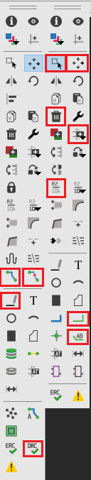
I didn't use all the tools I used only the tools that I need. the left list is for PCB while the right list for the schematic.
The Design rule checking (DRC) script shows an error when I loaded the file in eagle. because of that, I had to put a more space between traces.
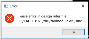
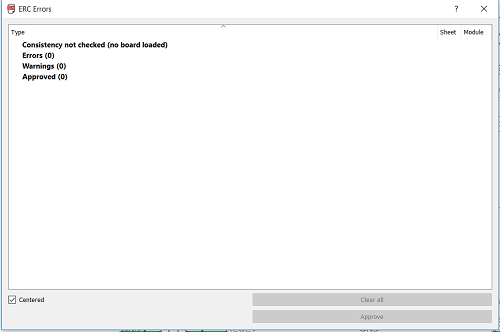
There is no error in ERC
Here is the hardest part. I don't know if it hard because this is my first time I do a PCB or its fact that is really the hardest part. Each time I reach the end I left with one trace that not connected and it cant be connected because it surrounded by other traces. Whatever, the width of my trace is 16 mil I thought that mil is a shortcut of a millimeter till Wendy told me mil refer to US measurement unit which is Thousandth of an inch and 1mil equal to 0.0254 mm.
This is my DRC settings

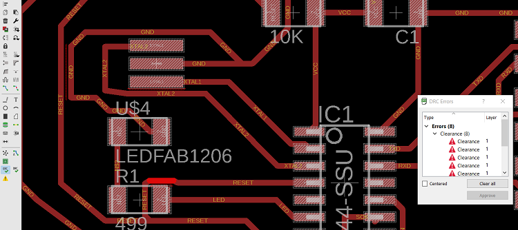
I found some errors. It shows that some taces are connected together.
I fixed all the errors.
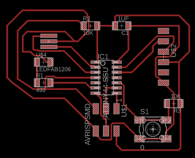
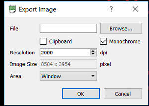
After I finished connecting all my traces. I had to export the design as an image to that I had to select the top layer.After I finished connecting all my traces. I had to export the design as an image to that I had to select the top layer. there is another way to export the image in eagle without cropping the image in paint I used it in input device week (link).

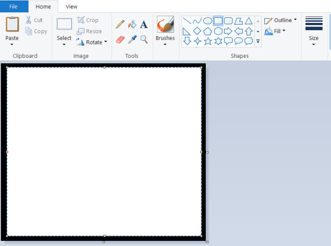
I used paint to create the outline image for FabModules.
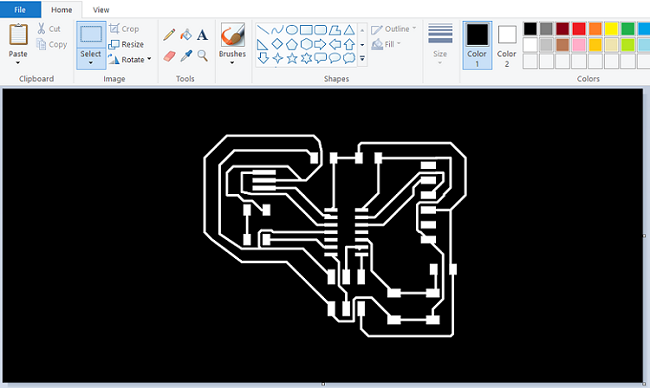
I used the crop tool to keep the trace area only then I seved.
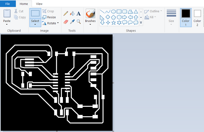
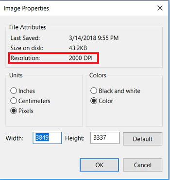
Before I saved my board image I checked the resolution if it changed after I crop the image.
To create the outline I select the rectangle tool and I changed the fill set to a solid color.
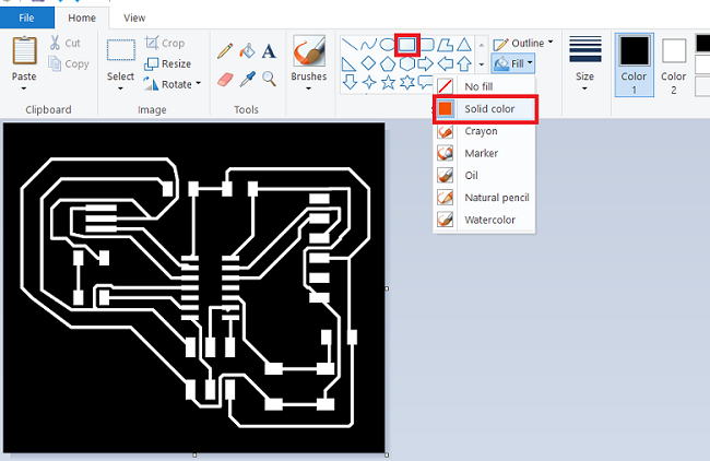
Create the rectangle on top of the trace image then save the file.
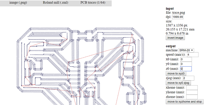
Now I have the two files all I need to do is to FabModules to convert to RML file. You can see some traces are connected. If I had my DRC file works I will not face this issue. I did the same procedure for the outline.
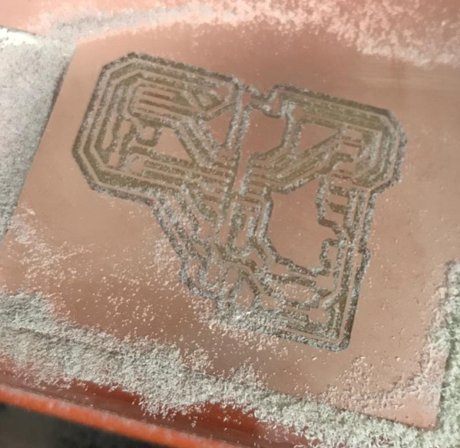
I had to make the distance between the traces wider because of this issue. I dont have a screenshot of it. but this is the way that I used to fix my board.
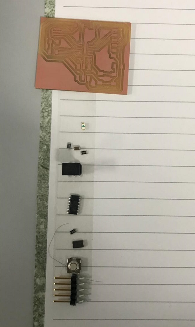
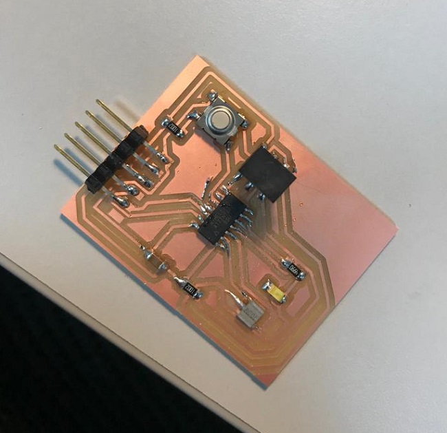
This time I was faster in soldering. because it's not my first time I did soldering in Electronic production week.
I did the smoke test and I test the connection by continuity mode in the multimeter. the multimeter beeps based on the resistance of the component being tested. I checked first the Vcc and ground then the other traces.
I did the smoke test and continuity test for the board same as I did in Electronics Production week and I programmed the board in Embedded Programming week.
File
BoardSchematic
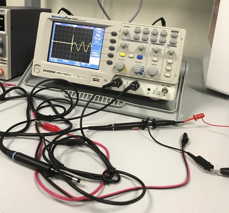
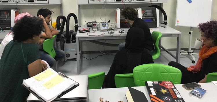
We had a session in how we use the oscilloscope by Gabriel Espindula. first, he showed us that is the difference between the analog signal and the digital signal. he talked about oscilloscope display and how to control the scales. the scales represent the voltages and time. he also explained the channels and how we connect the component that we want to measure with the oscilloscope.
I learned new stuff this week like AVRISP what does MISO and MOSI and SCK here good explanation. besides, I never programmed Attiny. I programmed before the Intel 8051. This is the first time I hear about FTDI cable I was knowing nothing about this cable.