Menu
HomePrinciples and Practices
Project Management
Computer-aided Design
Computer-controlled Cutting
Electronics Production
3D Scanning and Printing
Electronics Design
Computer-controlled Machining
Embedded Programming
Molding and Casting
Input Devices
Output Devices
Interface and Application Programming
Networking and Communications
Mechanical Design
Machine Design
Wildcard
Applications and Implications
Invention, Intellectual Property, and Income
Project Development
Final Project
Week 5
Electronics Production
Week Assessment :
Characterize the specifications of your PCB production process.
Make an in-circuit programmer by milling the PCB (program it).
so that you can use it to program your board in Electronics Design week, and in other weeks).
Optionally, trying other processes.
I have work with electronics component before, but this is my first time to use SMD component. I was very excited for this week it was finally I will do something that I know. At the end I done with this week and I am very happy. I learned new stuff I thought that I know like how to solder SMD component and I never make my own PCB so this part was totally new for me.
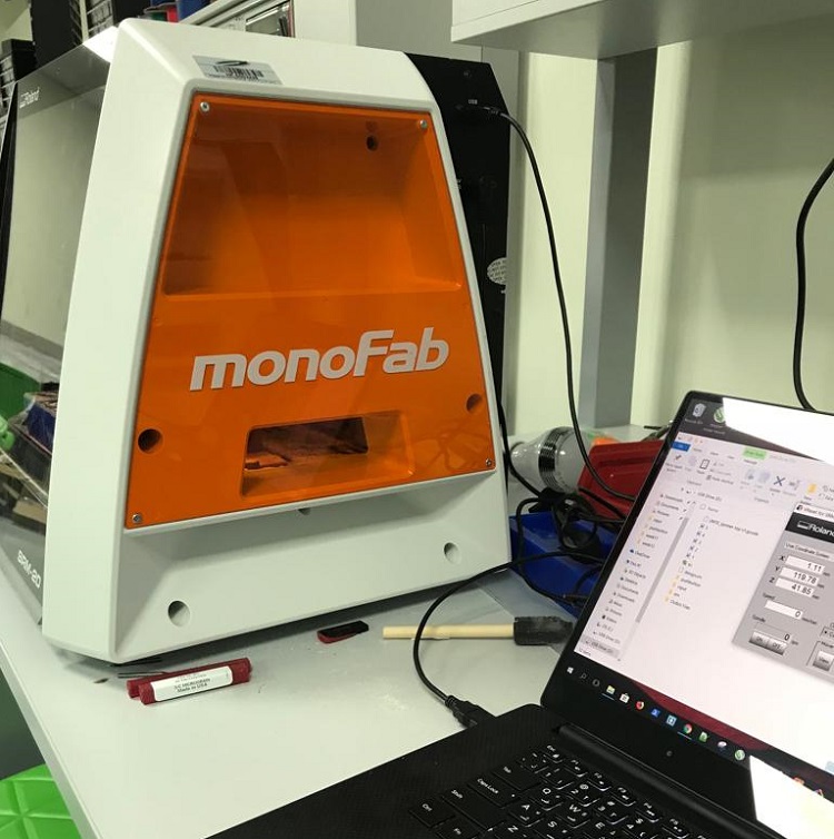
Machine : Roland monoFab SRM-20
Tools: 1/64 and 1/32
PCB materials: FR1
More information about FR1Firstly, we must prepare the documents for the machine.
I download the Board Files and Mill the Board. There are two documents 'png' ( outline and traces ). The traces are with 1/64, and to make the outline is 1/32.Then I have to sit the origin for the machine X,Y,Z.
Milling
We connect the RMS-20 with PC by cable.
Because we don't know how to use SRM 20 Wendy gave us a session on how to use the machine. This picture from the session.
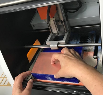
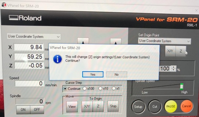
1- Put the tool 1/64 in the machine.
2-Move the tool of the machine with the 'x' and 'y' and to place it on the origin we need to click on the X/Y button on the right (to set the origin point).
3- To zero the Z origin to the machine, you will open the machine and open the collet the tool will touch the board then don't forget to close the collet and don't tight too hard . Now you can press the Z button on the right (to set the origin point).
I repeat the same steps for tool 1/32.
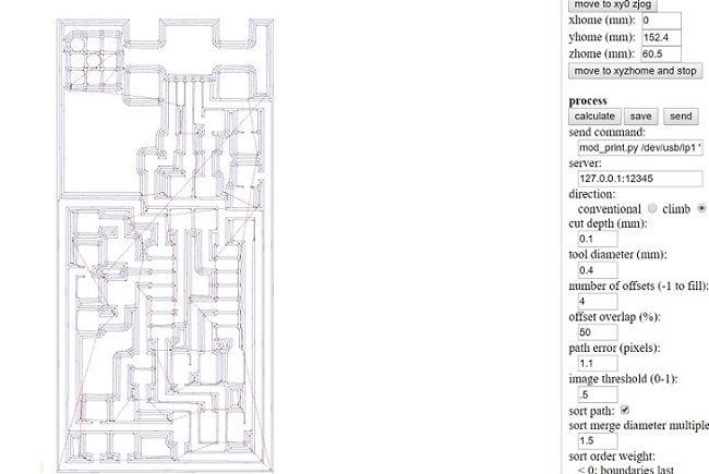
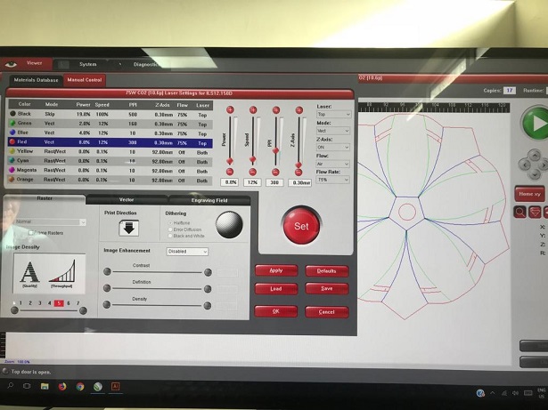
I used fab modules to generate a file for SRM-20. Here how it looks in Fabmodules this picture for the trace
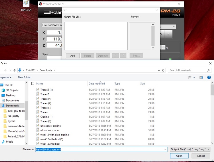
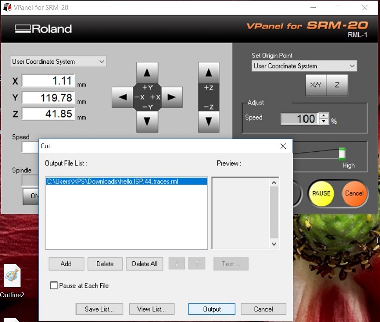
We download the file we get from Fab Modules. We press Cut, then we select the rml file
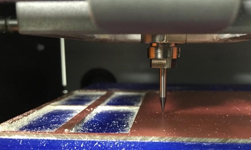
Then press output
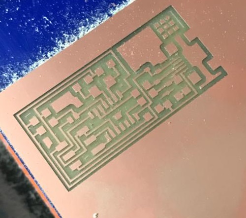
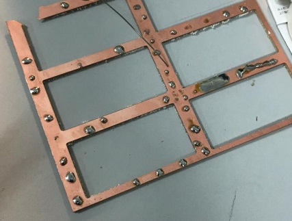
Below this how it looks in reality.The SRM-20 removes the copper by the mill bit so you left only the trace that you need for connection and placing the component.
All the files are on the tutorial page for Fab_ISP
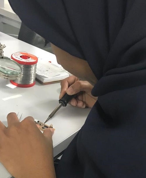
Soldering
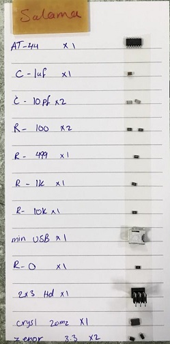
All components have been stuck on paper by two face tape. They are very tiny. This is the first time I solder with size of components.
I did some soldering practice in unused PSB and then I try to solder some component before I work with my board. It was hard the see between the USB pins. I soldered two pins by mistake and I learned how to fix that. by using a desoldering pump.
Testing
We test the connection by multimeter using continuity test mode and we follow the ground and Vcc. The other test we do is smoke test, by connecting our board with pc and we should check if there are smoke smell or not. My board pass these two tests successfully.
Programming
My laptop has Windows 10 operating system. I followed this tutorial for Windows 10. I got this link form Carl So, I had to download and install this four software which are:
1- Atmel GNU Toolchain
2- GNU Make
3- Avrdude
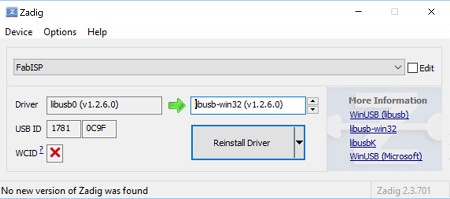
4- Zadig
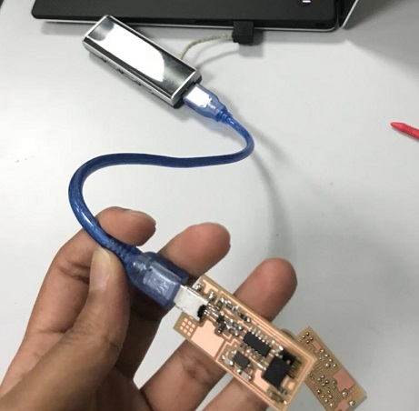
I downloaded all this four software and I had to set the driver from Zadig and my FabISP should be connected with another programmed FabISP.I used Zahrah FabISP her board already programmed. This is the only steps where I have to connect my FabISP with another in the installing process. Connecting the two board headers and the USB cable to the computer.
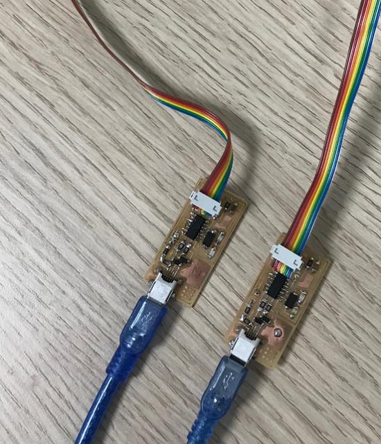
The boards get programmed from ISP headers. All that we did now is to make the operating system initialize the board so still, the board did not get programmed. Even if you get done with his steps don't remove any wire keep the connection the same you will need it to program your ISP.
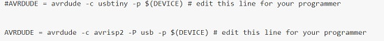
Download makefile and edit this two lines by swapping the hashtag. I did it in Brackets
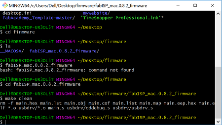
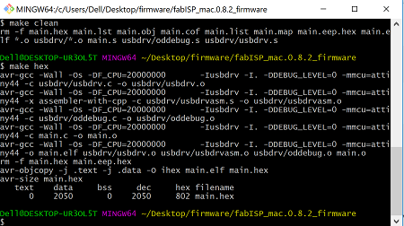
I opened Gitbash and I followed the tutorial here some of the commands that I wrote in Gitbash.
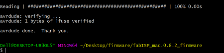
I wrote a make fuse and then make program and this was the last message I got.
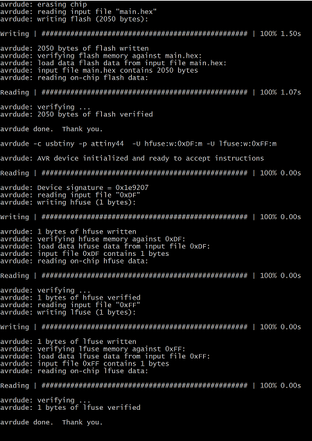
The last step is to remove the jumpers on the board. Finally, I succeed this week. At that time I didn't take a screenshot but I use it for programming my input and output boards (link).
Troubleshoot
My first circuit didn’t work I don’t know why. I tried to follow every troubleshooting technique but it didn’t work, so I make new one and I go through the process again. That will help me to find where I did wrong. When I did the programing, I got error massage. Then I realize the I did not solder one if the USB pins properly. After I fix the soldering it works fine finally.The pins for Attinyn are really close to each other. Now I am much better at soldering SMD component.
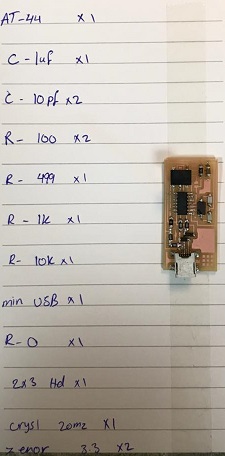
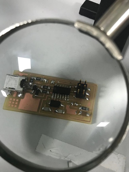
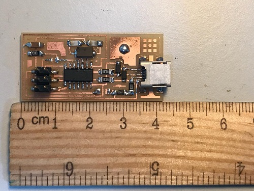
This is my new board. I did soldering mark cause I don't want to get confused
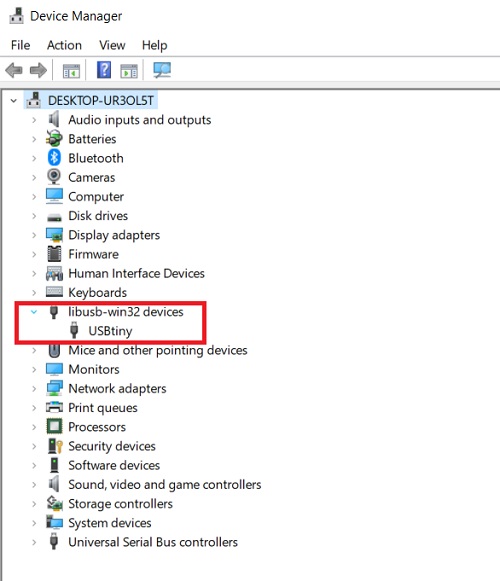
In Device manager will show my board as USBtiny.
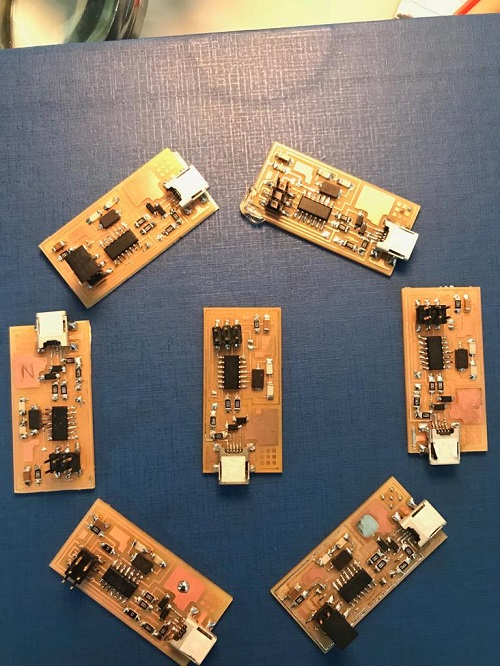
All our boards
Other activity
We will have this mini maker faire here for a few days. It starts on Thursday, so we prepare for the faire.

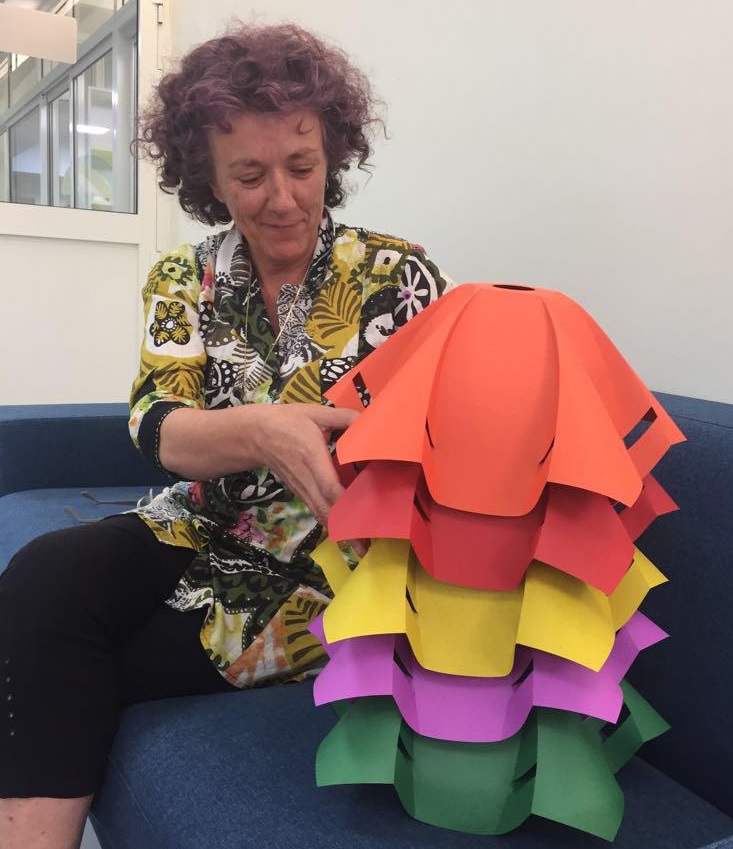
Our instructor and friend Wendy designed a lamp and she showed us how she did it. She used laser cutter to cut colored papers. We will be showing the MakerFaire visitors how to do it. We will also have our booth for showing our Fab Academy, and we will be making our 3D print assignment during this. Also learning how to use a scanner.
We will join the hackathon which is part of the MakerFaire. We will be making some ideas that kids imagined, and we selected the Prayer Mat for blind people. It will help a person find the direction they must face to pray. We call that direction qabalah. This is the first time I have been in a competition or hackathon, so I don’t know what it will be like – I’m looking forward to it!