Menu
HomePrinciples and Practices
Project Management
Computer-aided Design
Computer-controlled Cutting
Electronics Production
3D Scanning and Printing
Electronics Design
Computer-controlled Machining
Embedded Programming
Molding and Casting
Input Devices
Output Devices
Interface and Application Programming
Networking and Communications
Mechanical Design
Machine Design
Wildcard
Applications and Implications
Invention, Intellectual Property, and Income
Project Development
Final Project
Week 9
Embedded Programming
Week Assessment :
Read a microcontroller data sheet.
program your board to do something.
I started this week with a session about programming with Hashim. The good thing about this week is that I have a good background in programming with c++ language. We used Arduino IDE software to write our code. I found difficulty to design a bored in electronics design week and I used the same board to program. I learned from Hashim how to add the fab library in Arduino IDE. I must use FabISP the one that I made in week 5 to program our board. AVR microchips need a programmer to get programmed, so my FabISP is my programmer I need it to program all the board that I will design it in future. The first thing that I did in this session was to download the Attiny board into Arduino IDE. In this website coped a link and paste it into the preference in Arduino IDE
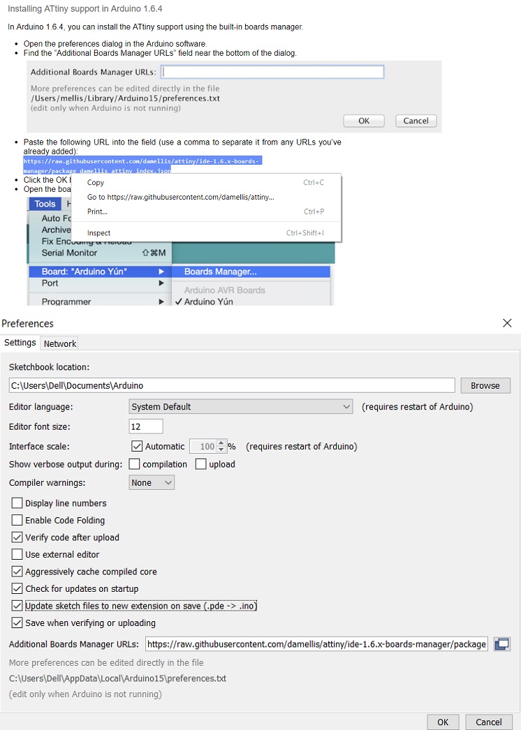
Tools > Board: > Boards Manager
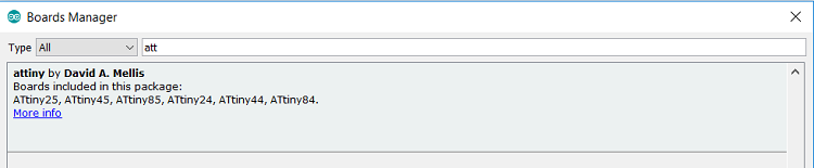
After I installed the Attiny boards has bee added to my boards list.
I have read many of datasheet when I was studying that why I know how important to read it. Datasheet helps you to know each pin used for if it microcontroller and for the cable will helps you to understand the color code. If you did not know each pin used for I will not be able to program the microcontroller chip, so it necessary to read datasheet. Another point is it is unpassable to read the entire datasheet you only need to go though it very quick looking to key word or graph the summarize that data.
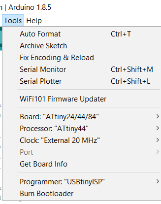
I did what I usually do and what Neil recommended is to look to attiny44a datasheet. You must put the full model name of your microcontroller in search engine, so you get the correct datasheet.I'm using FTDI cable to send PWM signal to program the Attiny 44
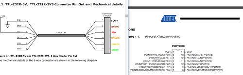
So what is PWM is a type of digital signal that have two level High and Low. In my case Im using FTDI cable that send 5V to the Hght level will be equl to 5V while the Low level equl to 0V.
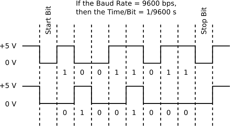
There are two main protocols for serial communication, TTL and RS232. The major difference between the two is the voltages that encode the bits. TTL encodes zeros with a voltage of zero and ones with a voltage of 5 V (or 3.3 V). To increase data integrity, RS232 encodes zeros as +3 V and ones as -3 V. This information from this webpage
For the information I got in datasheet I could be able to edit the button program.
I change the button pin from 2 to 3 and the led pin from 13 to 7 and I send it to the board without any problems and it works. Then I send the blink program and I changed the led pin from 13 to 7.it also uploaded to my board without difficulties.
I was happy the download the program to my board without any issue. That give my time to help my friends. I was walking around looking for any one that need help. In this week I felt confident that I did my work fast and the good thing is that I found the time to explain for my friends what they don’t understand it. Here where I felt that I’m useful I got the chance to transfer my knowledge to someone, and I hope that I did like what my group expected form me. I did much more in the programming for Input Devices and Output Devices.
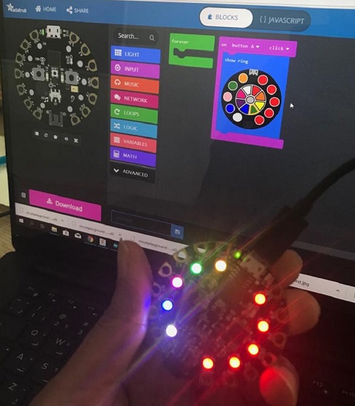
I also tried to program circuit playground. In the regional review Duaa from Bharain programmed circuit playground. I liked what she did so I went throw her page and I opened the link for Adafruit Adafruit make code I played with blocks and this is the first time I programmed a board with blokes. It might be easy for beginners but I faced difficulty to program a board with this method. Maybe because I get used to the C++ code, the good thing is Adafruit added javascript option. But I challenged my self to program circuit playground with blocks. I did simple code which changes the LEDs colors. Then I tried to add some sound. the way of uploading the codes are interesting. I followed the instructions
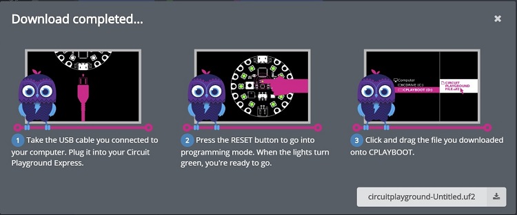
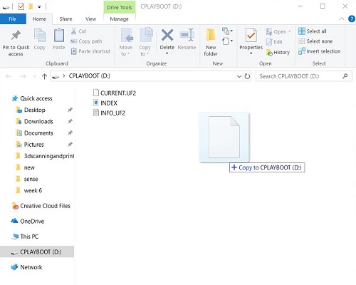
I had to download the file and connect the circuit playground with my laptop. I kept holding the reset button until the green light appears.
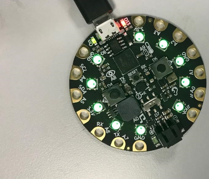
Then it will show as flash memory copy or drag the code file into the circuit playground then the board will be programmed.
File
LED with buttonCircuit playground code file