Ambitious intellectual, always looking forward to improving myself and widen my knowledge. Passionate about designing. Skilled in tooling, design engineering and problem solving . A good team player with great organizing and communication skills. Driven by the thirst to seeking knowledge and growth in experience.
Week Objective: To learn and understand the programming language HTML used to build web pages. And to be able to upload it to the internet using Git software. Then to apply our practice and acquired knowledge to create our own website. This website – the one you are browsing now – is built to present our personal profile and document our experience throughout the program of Fab Academy.
final result: This WebSite!
Week 3
Computer Aided Design
Week Objective: To learn and use 3 different softwares, two for 3D design and one for 2D design. And apply our leant knowledge in designing our final project. The design must be parametric. .
final result: Softwares used are: SolideWorks, Fusion 360 and Adobe Illustrator.
Week 4
Computer Controlled Cutting
Week Objective: To learn how to operate the laser cutting and the vinyl cutting machines. For the vinyl cutter, to print and cut a designed poster. For the laser cutter, to cut and assemble a press fit construction.
Final Result: A structure of assembled pieces of cardboard, and some stickers for Naqsh.
Week 5
Electronics Production
Week Objective: To learn how to use the PCB milling machine and manufacture a pre designed PCB. Then after the milling and soldering, to program this piece.
Final Result: Created and programmed an ISP.
Week 6
3D Printing
Week Objective: To become familier with the skills and knowledge to operate on 3D printers. We are tasked to create two printed objects using an FDM printer and an SLA printer. And to learn to scan objects for 3D printing.
Final Result: A designed plants pot using FDM and a scanned person using SLA.
Week 7
Electronics Design
Week Objective: To learn how to create a schematic for an electric board, route it and then program it.
final result: Created a PCB with an LED built in to indicate its functionality.
Week 8
Computer Controlled Machining
Week Objective: Learning how to function the CNC machine and create things using it, minding its parameters and constraints. We are tasked to create something big without the use of any screws, bolts or glue. Only fitting assemmbly.
final result: A chair with and adjustable back, and a living-hinged seat.
Week 9
Embedded Programming
Week Objective: To practice different programming languages like C, C++ and Assembly. Then Choose one of them to program our Hello-World board from week 7 using our FabISP as programmer from week 5.
final result: A Hello-World board that turns on the LED when the button is clicked and turn it off when the button is clicked again.
Week 10
Molding and Casting
Week Objective: To design and create a block for molding, then cast it.
final result: Small molds in different shapes.
Week 11
Input Device
Week Objective: To create a device that reads a signal and send it to the computer giving useful data.
final result: input device for the final project.
Week 12
Output Device
Week Objective: To create a device that carries commands or display data that were measured using an input device.
final result: The electronics system for the final project
Week 13
Applications and Implications
Week Objective: Make a research about similar projects to my final project, review them, then reflect on my final project; how will it be made, what components or process do I need, and what is the function that it will carry?
final result: A study and a plan to carry out my final project.
Week 14
Networking and Comunication
Week Objective:to connect two boards of my creation through serial communication.
final result:Two boards, one reading an input signal and send it to the other to give an output basing on that signal.
Week 15
Mechanical Design
Week Objective:We, the students in Fab Lab Irbid, are tasked as a team to create a functioning fabrication machine. This week, the task is to poltout device ad create and aasemble the mehcanical parts.
final result:Wall Printer body assembled.
Week 16
Intefrace and Application Programming
Week Objective:To learn a programming language, and use it to create an interface to control an electronic board.
final result:a Python program, created a window with three buttons to control three different colours of LEDs.
Week 17
Machine Design
Week Objective:After assembling the machine we wroked on two weeks ago, we have now to program then machine and make it capable of carrying out a job.
final result:Wall Printer.
Week 18
Wild Card Week
Week Objective:This week is to make and learn something new. I went with composite material.
final result:Sword's scabbard
Week 19
Invention, Intellectual Property, and Income
Week Objective: This week we have to search for licensing party to register our projects. And discuss our plan on what we aim to do with the project (commercial use, personal use.... etc).
final result:Licensed my final project.
Week 20
Project Dvelopment
Week Objective: To persue the working on our final projects
final result:Organizing my tasks and preparing for the final project.
Final Project
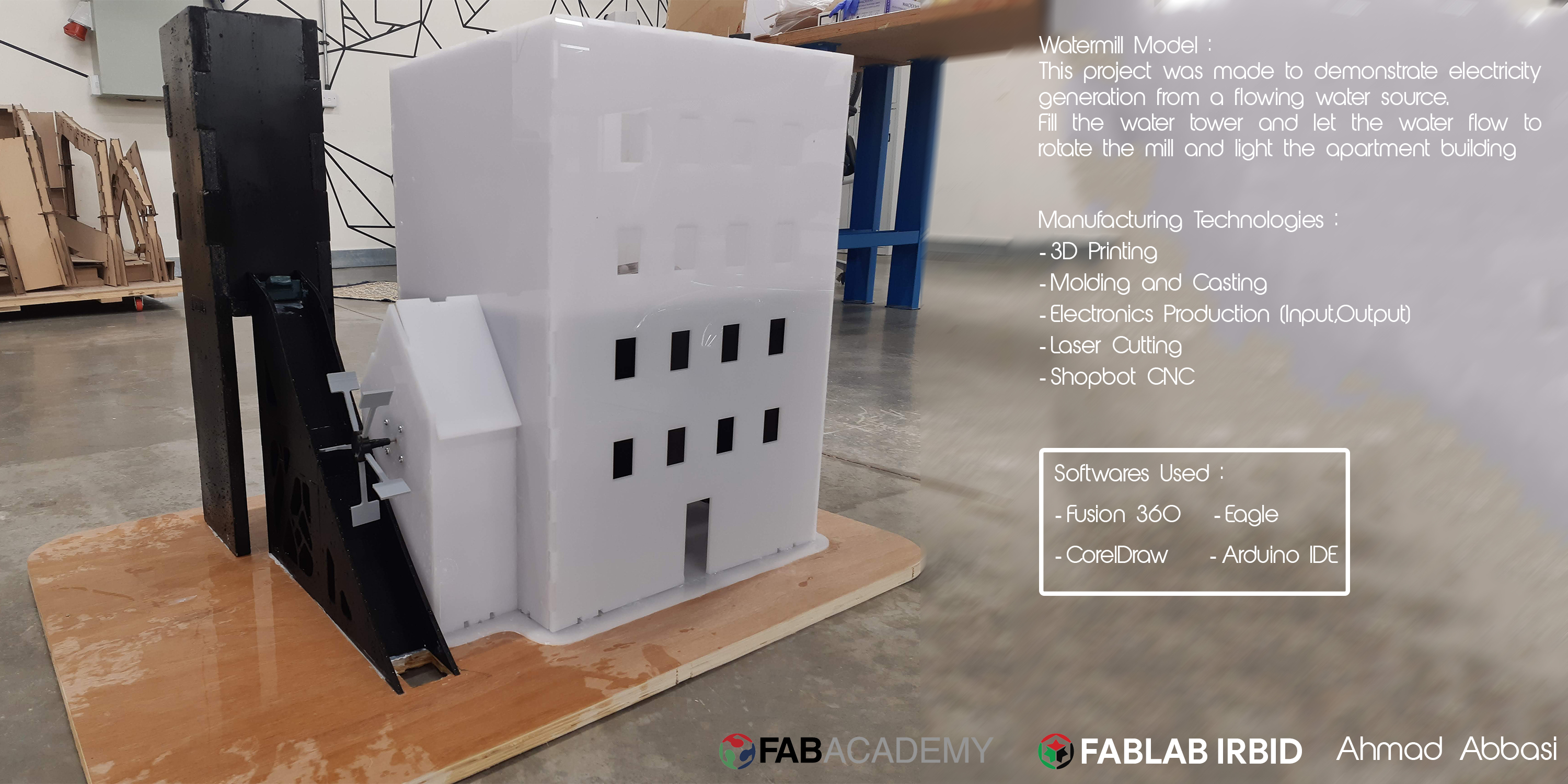
Watermill Demonstration
Plotting for the final project.
As one of the team working on Naqsh Initiative and I am supposed to build demonstrations to explain science applications to the kids. I decided to make one of those demonstrations as a final project for Fab Academy, applying the fabrication technologies I learnt. The project is to build a model of a watermill to explain how we can generate energy by converting the kinetic energy to electrical energy. Although I am not going to actually generate energy, but rather take a signal from a DC motor to a controller, witch in its turn light up a small building.
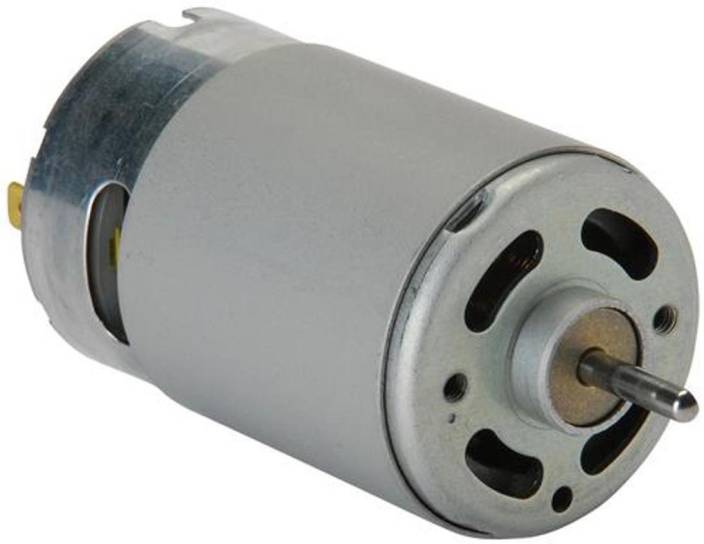
The DC motor should send a signal when its shaft rotates. That shall happen when water is poured through the path passing by the watermill.
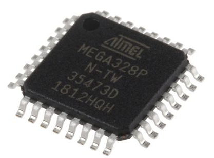
Inside the building, will be the electronic components. I'll be using an Atmage board to control the system,
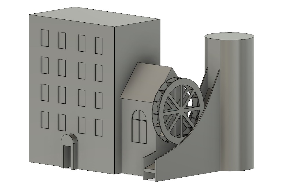
For 3D design, I used Fusion 360 to model my components. To further understant how to work on Fusion, check my Assignment No. 3
Electronics Work
The fist step I took in building my project is to take a signal from the DC motor and test it on the serial monitor. Check my Input Device week to see in details how that was accomplished.
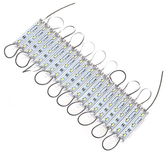
After creating a microcontroller to read the signal, I had to connect it to the output device and program it to turn it on at certain conditions. My output device was the LEDs which function at 12 volts. For that I had to create a mosfit board to take the signal from the Atmega chip, and lighten the LEDs using an external power soucre. The details on creating the mosfit and testing the system, also the fullcode to control the system, are all found in my Output Device week.
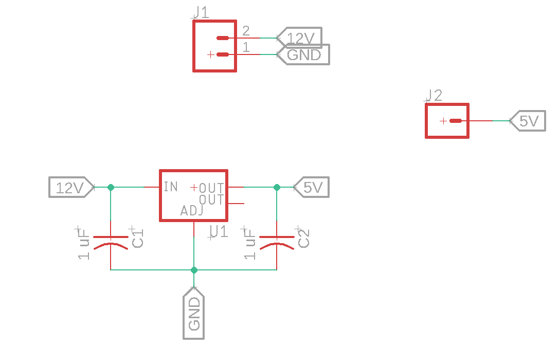
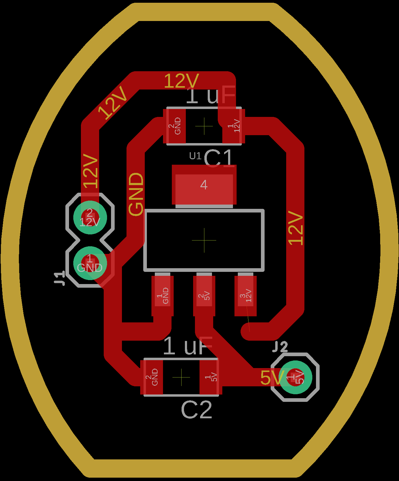
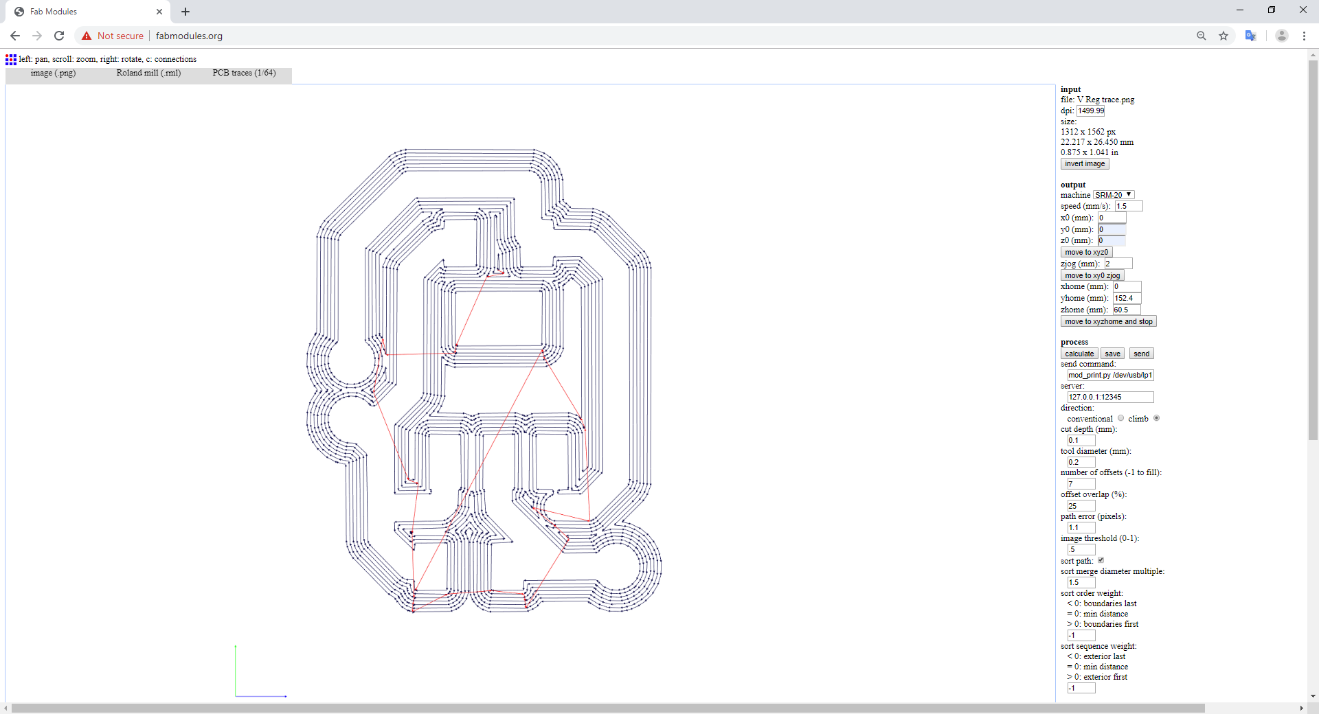
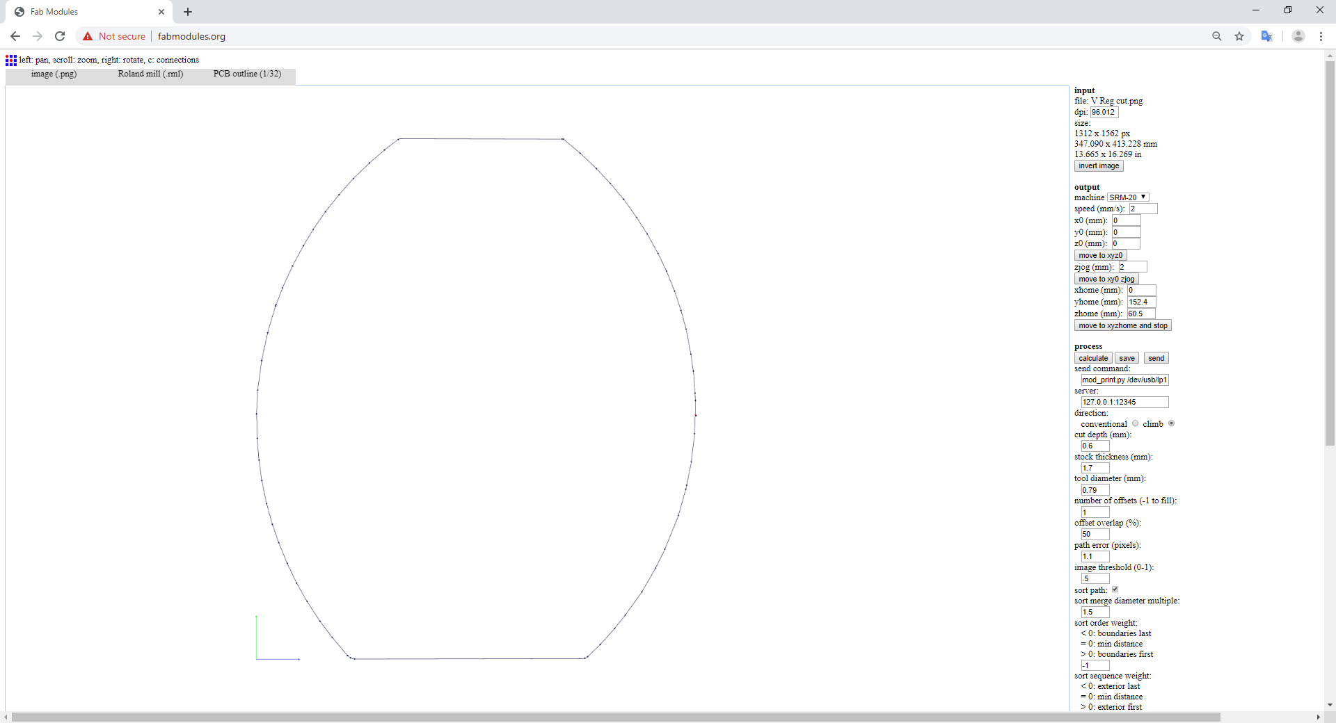
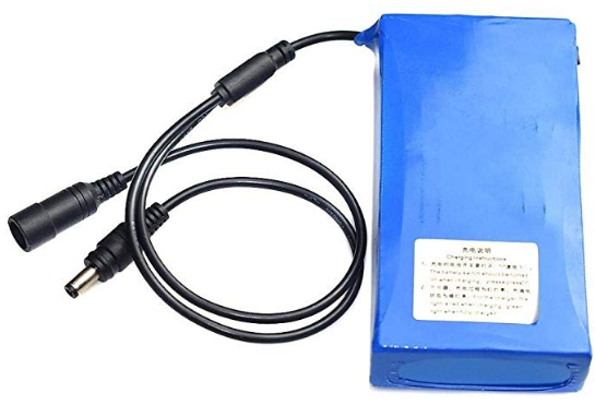
The final piece of electronics I had to create was a small chip with a voltage regulator. I need to power my Atmega board on a portable source rather than a computer, so I had to make the regulator to take the battery's 12 volts and transform them to 5 volts for the Atmega.
After finding the available regulator and studying its datasheet, I created this schematic.
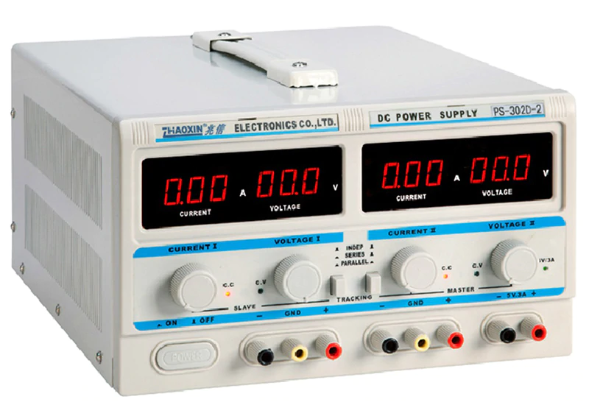
After creating the voltage regulator, and before connecting it to my system, I had to test it. Because I don't want any error to cause an excissive power of ruining my boards. And to test it, I used a power source, setting the input voltage to 12.4 volts (just like the lithium battery I am using) and limiting the current to 1 A to make sure it wouldn't hurt the mosfits. Then I used a multimeter to test the output voltage and found it equal to 5 volts, which is my demand.
At first, I tried to create one blade from the mill's blades using 3D printing, then mold it and cast it. But than did not go efficiently for the blades are too thin.
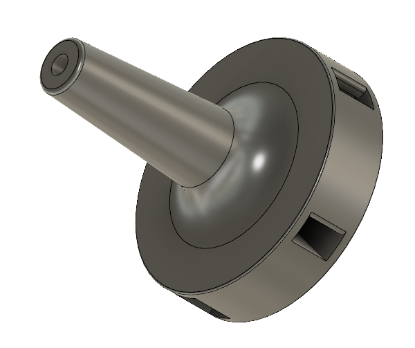
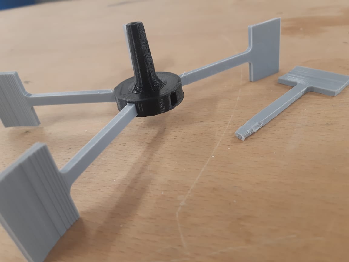
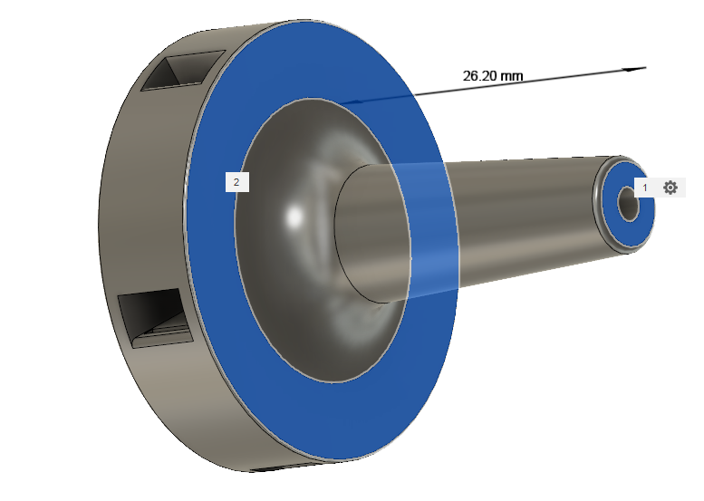
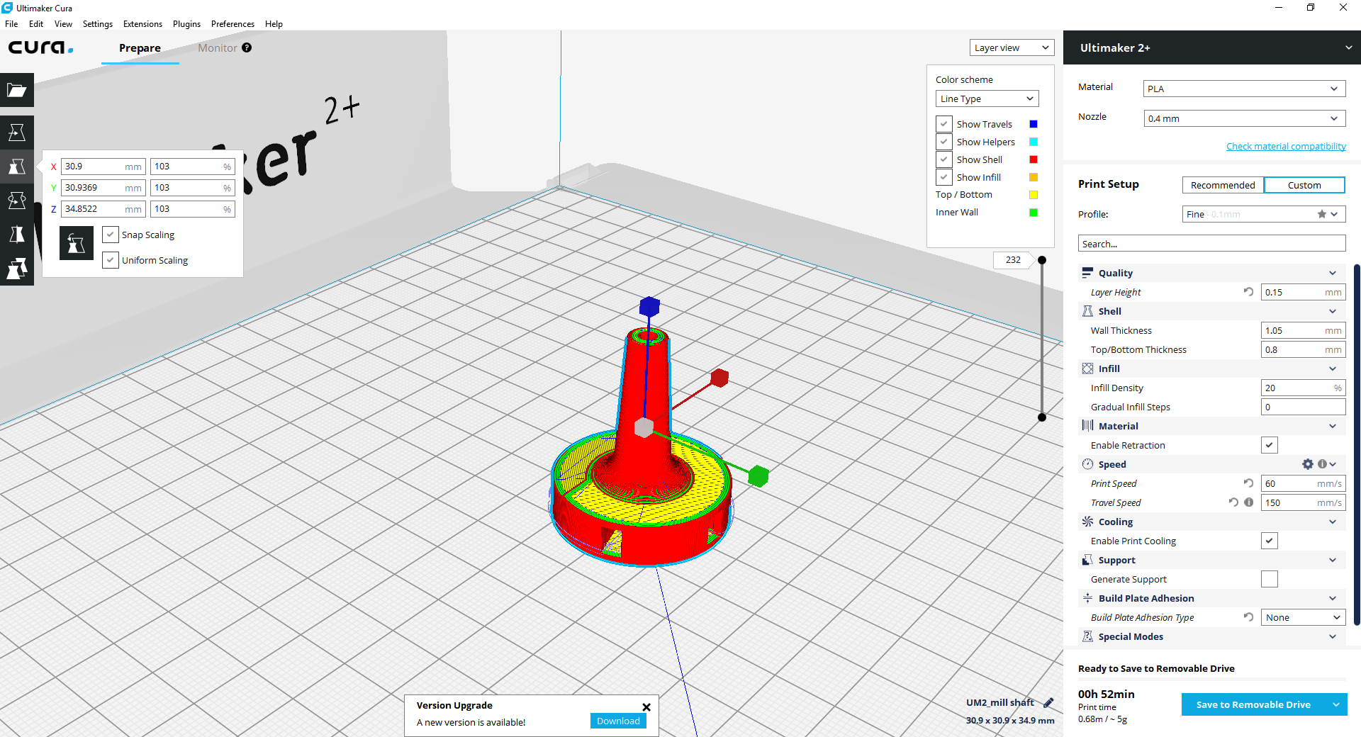
Hence, I decided to create the endmill using 3D printing. Creating a holder to be hooked to the motor's shaft, and attach 5 blades to it.
For designing the middle part (the black one) the most important dimensions were the diameter of the hole for the shaft and the length of the shaft extruder.
An important characteristic in the shaft attachment is to have a long enough leg to allow the blades to rotate without touching the building wall.
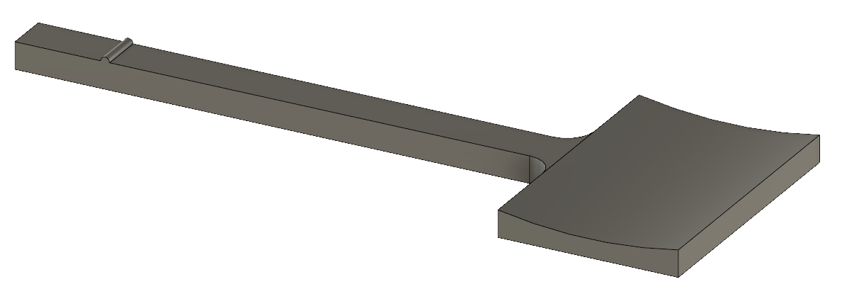
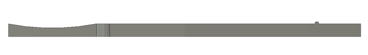
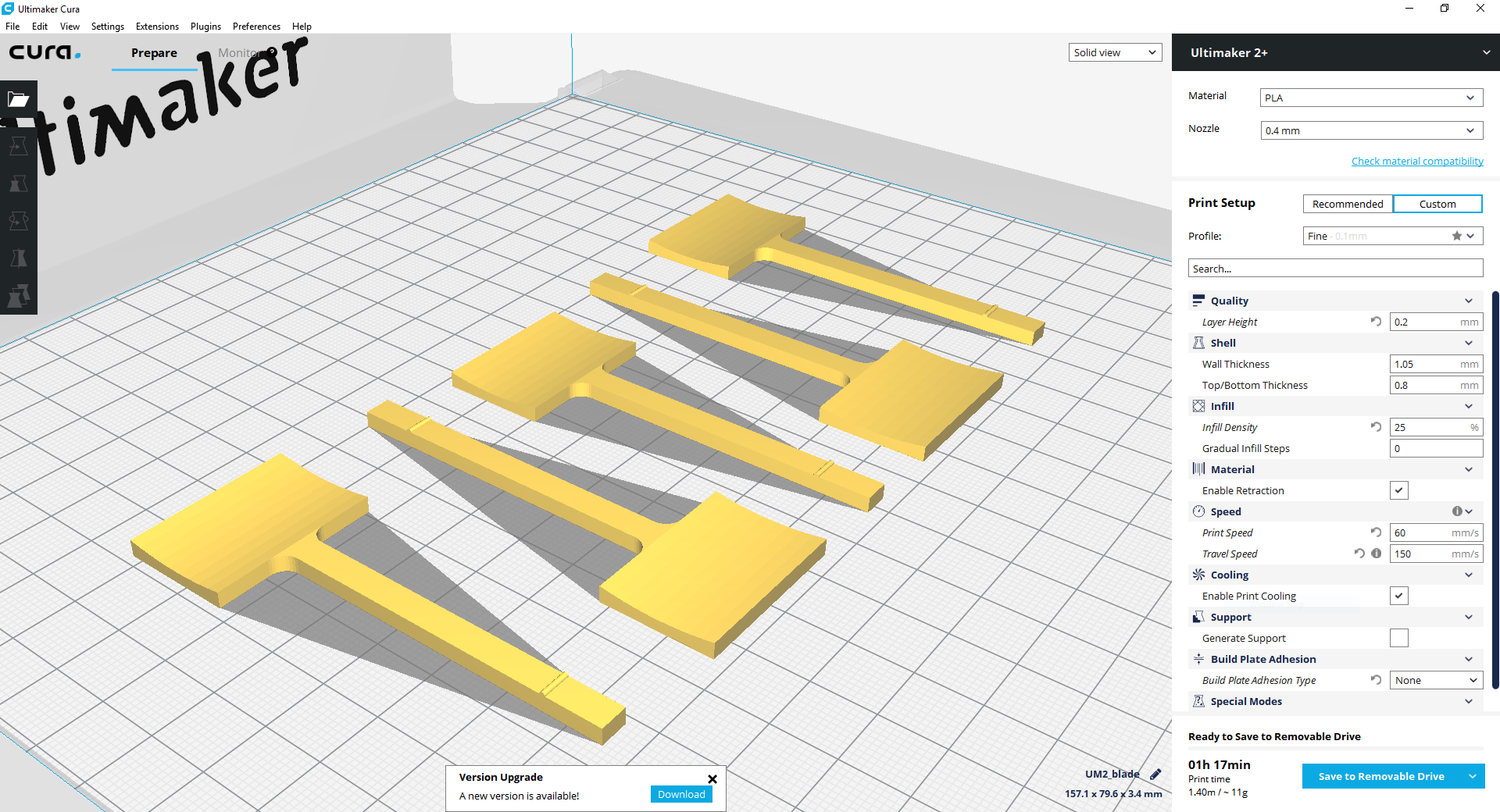
And for the blades, their length was important. And to make sure the inserted part of the blade in the black disk is equal in all the five blade, I extruded a small tooth.
To further understand 3D printing process check Assignment No. 6
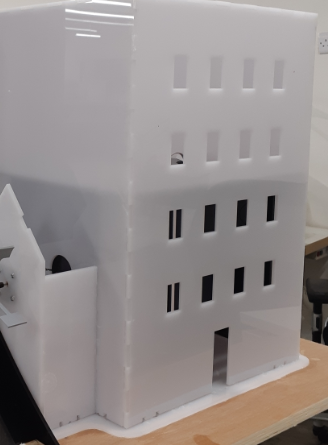
The Building
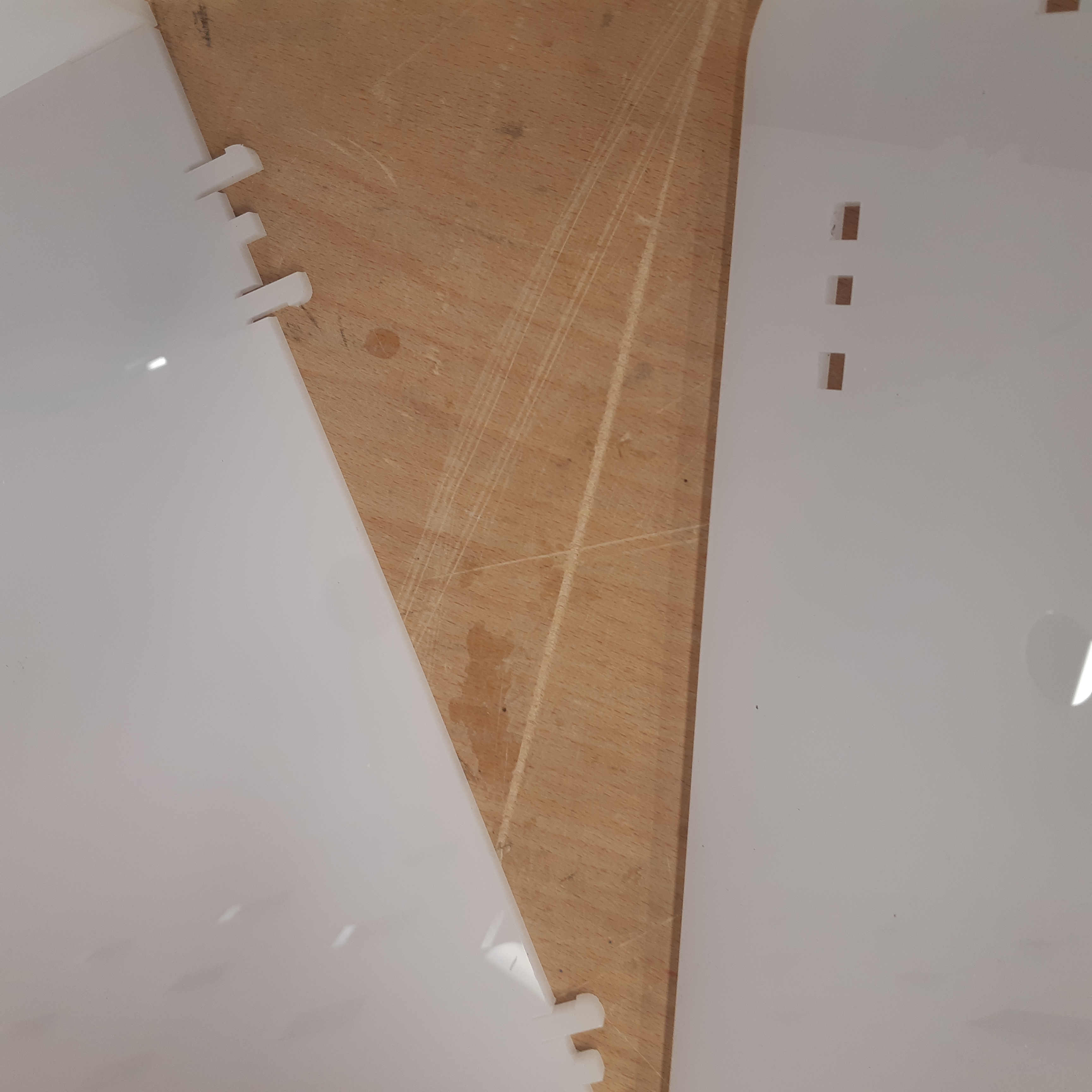
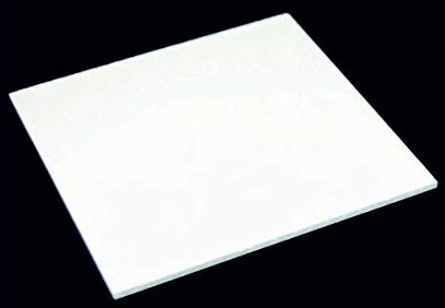
For the building, I used white acrylic boards of 5mm thickness. made the design, then manufactured them using the laser cutter. The building is devided to two sections, the apartment; and that is the big one with windows adn supposed to light. And the small house next to it with the main role of simply holding the watermill. Then the aparment was devided from the inside to two levels, because I wanted half the building lightened on low rpm, and fully lightened on high rpm. The divider was made using black arrylic board of also 5mm thickness.
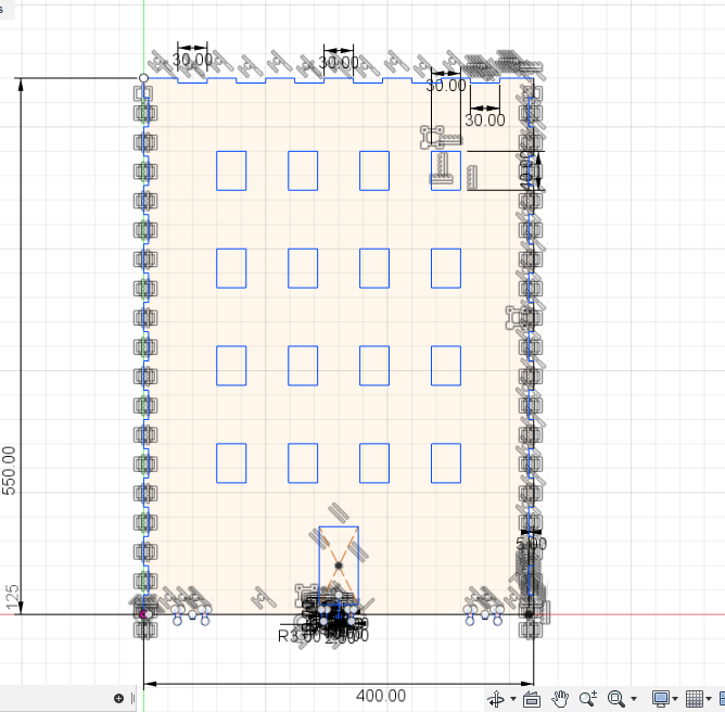
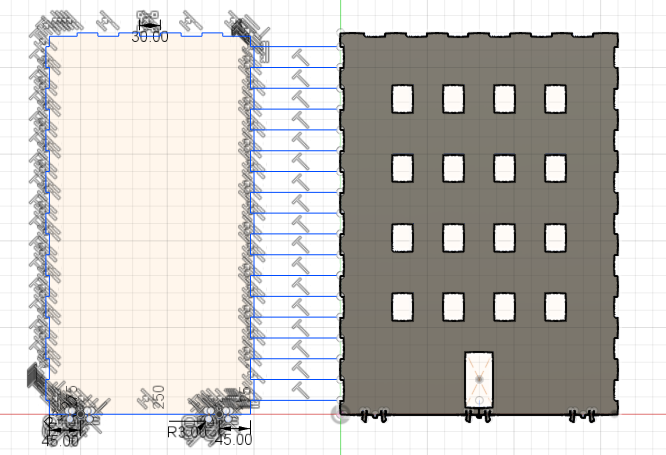
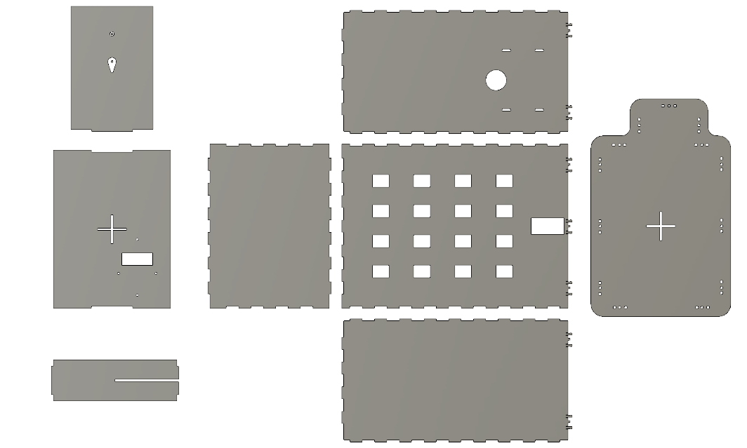
Desgining, I started with the front face of the building to design, sketched it and added all the fingers for joints, then started sketching the other faces next to it so it would be easier to mach the joints.
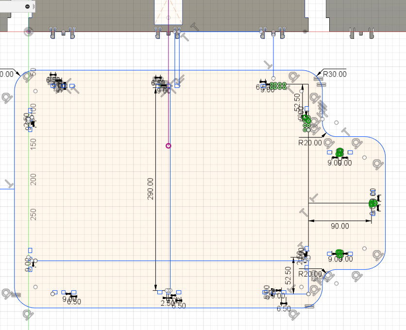
And the same way for the base plate...
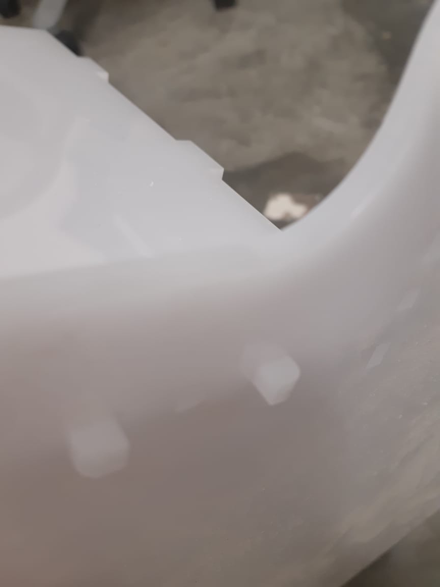
To assemble the walls with the base of the building, I used this type of joints:
In the back wall of the buildng, I made a living hinge to create a sort of a door so I would be able to access the internal components of my project.
After designing the building on Fusion 360, I created a drawing from the design, saved it as a PDF to open it and adjust it on CorelDraw.
To further understand laser cutting process check Assignment No. 4
Water Tower
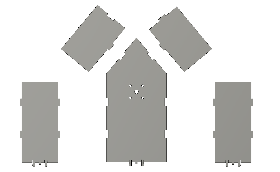
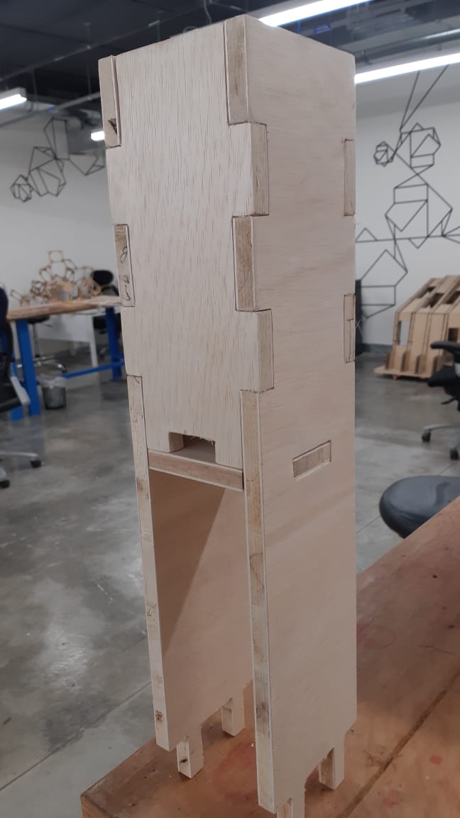
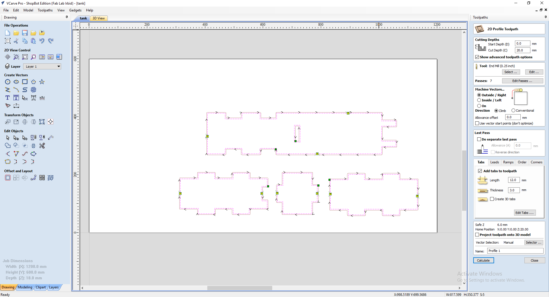
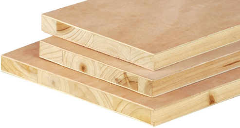
The tank tower was created using Latte wood in the shopbot CNC machine. And the same way as creating the building, I desgined the tower on Fusion 360, created a drawing, saved it as a PDF, then opened it on V Carve to adjust it.
Same way as the building, I started with one face, then the others matching the joints.
After the machining process, I had to sand the tank and assemble it. I used glue to hold the joints tight, then sealed the clearences with silicon so the water would not leak out.
The tower was sprayed with a black paint for aestheric appearance.
Job Settings for Machining the Tower:
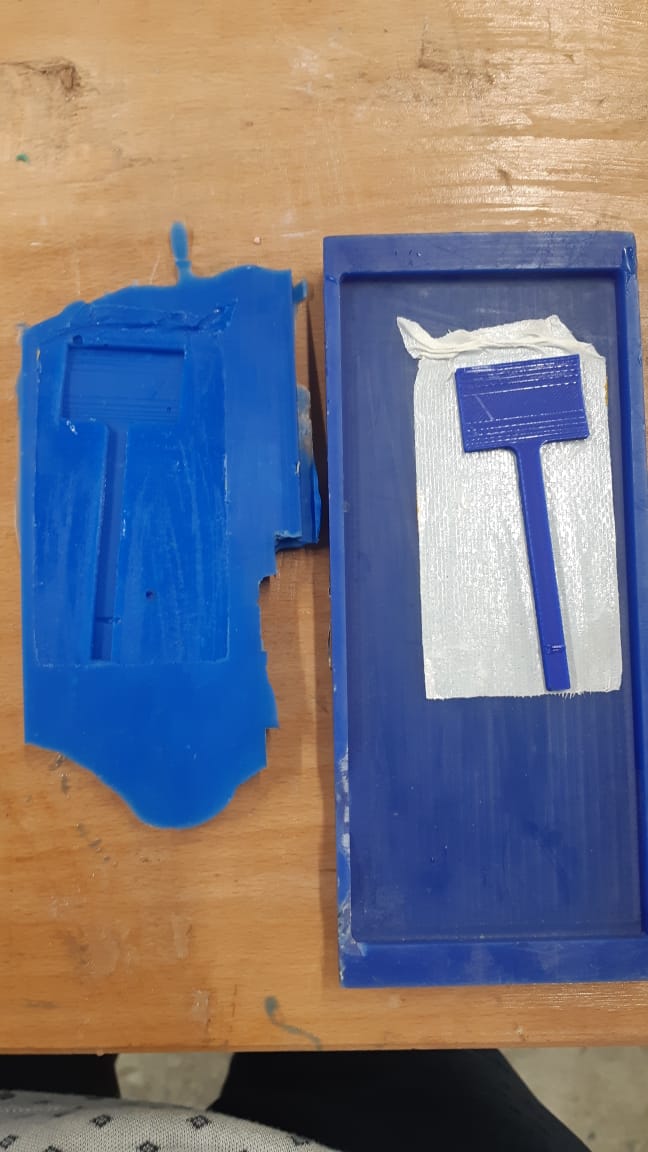
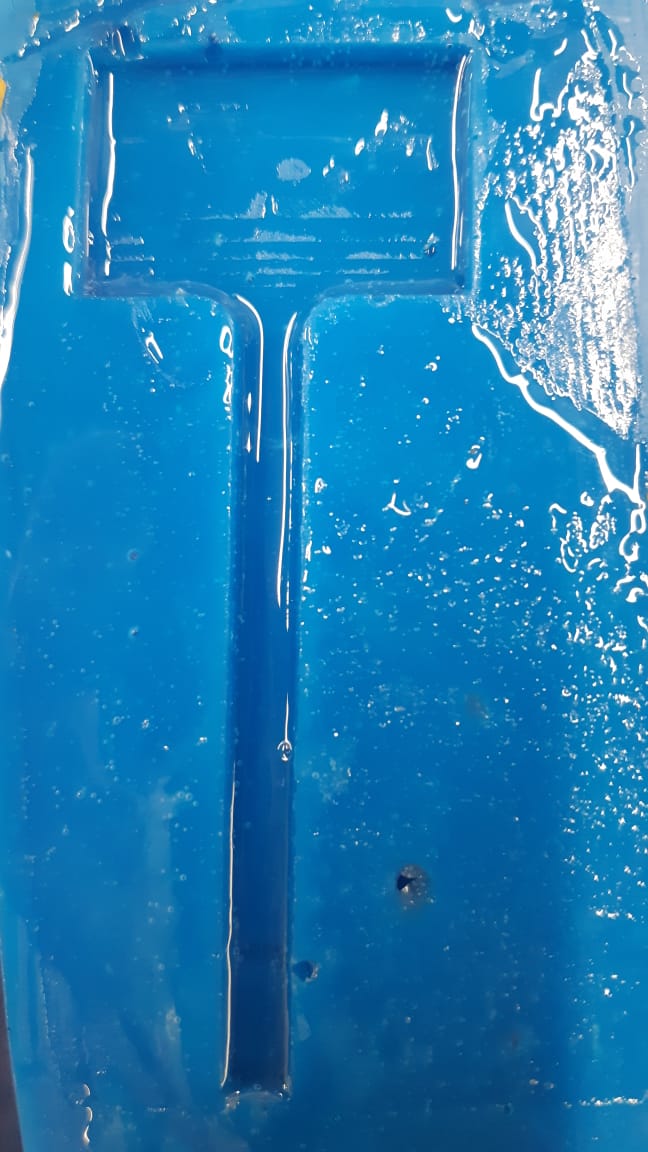
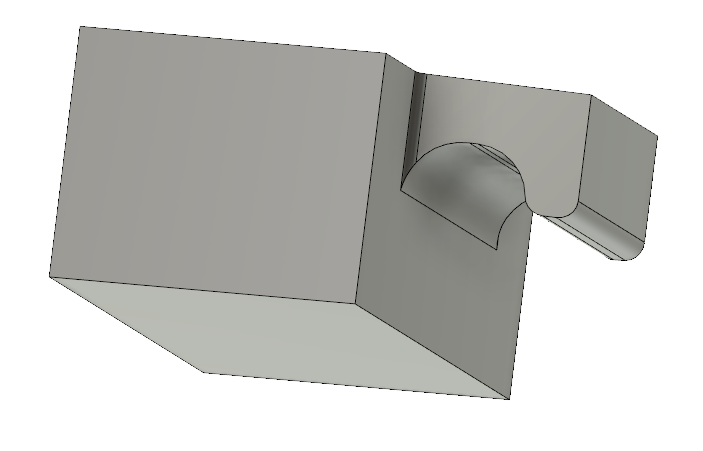
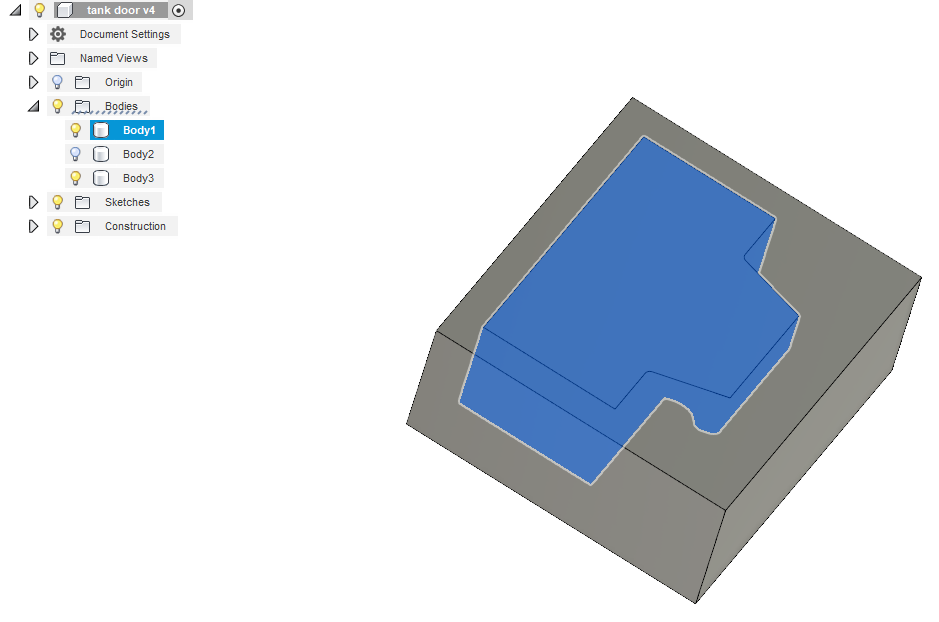
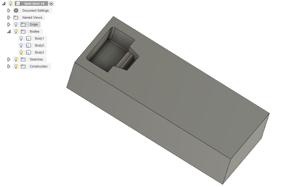
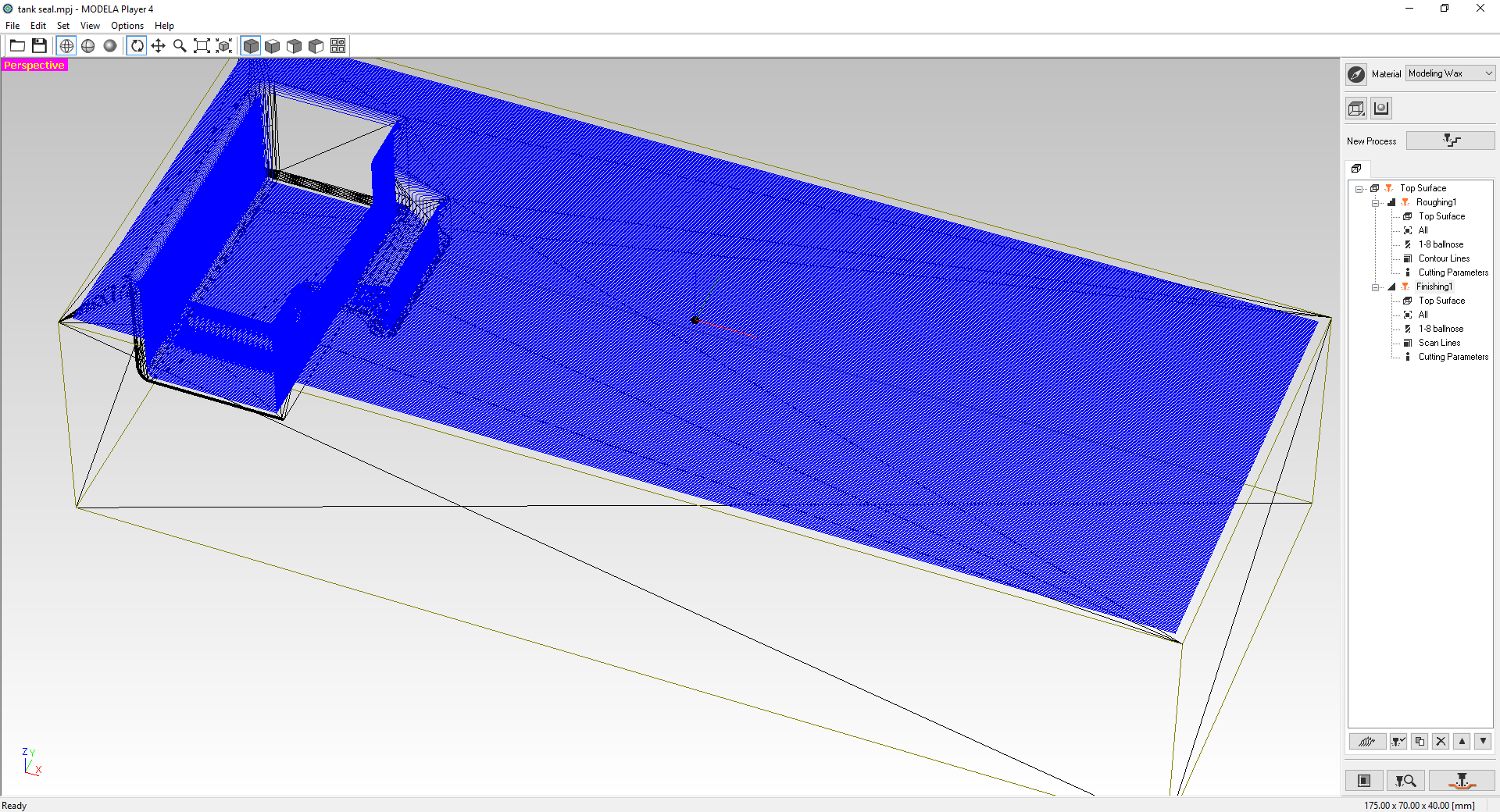
I then created a cap to lock the discharge door of the tank using molding and casting.
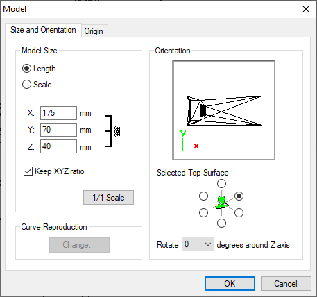
I design the mold using Fusion 360 then saved the design as an STL to open it on Modela Player and create the mold on a wax block using the Roland CNC.
In the desgin, I desgined the cap first, then the block overlapping the cap, then used the splitting tool.
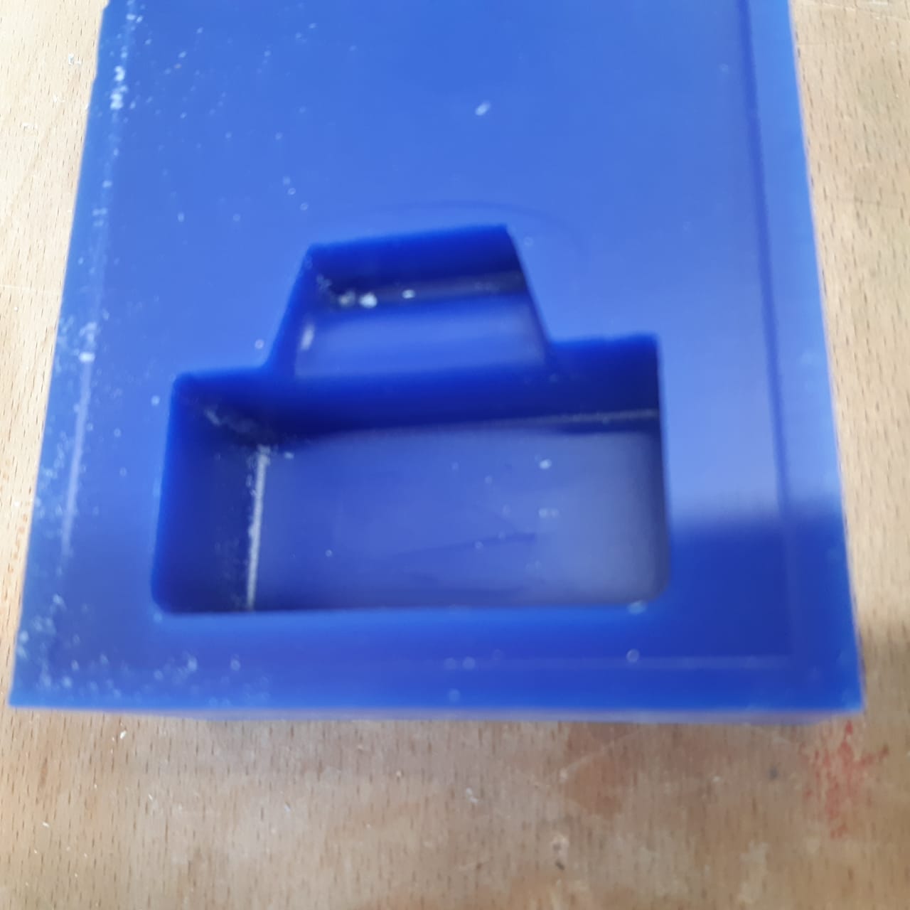
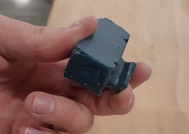
Then I used Sorta Clear silicon rubber to cast it, with a bit of colouring dye.
To further understand how to work on the Shopbot CNC check Assignment No. 8
To further understand molding andcasting process check Assignment No. 10
Water Slide
For the water to flow, I created a slide connected to the tower and passes in a measured distance undet the motor shaft,so the stream would flow down its slope moving the watermill.
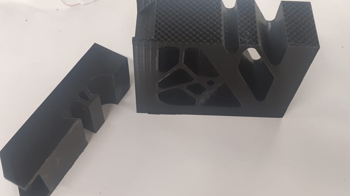
To create this slide, I designed and 3D printed it.
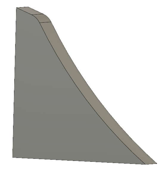
First designed the slope...
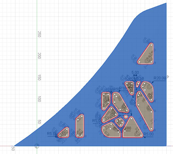
Then the edges to keep the stream atop...
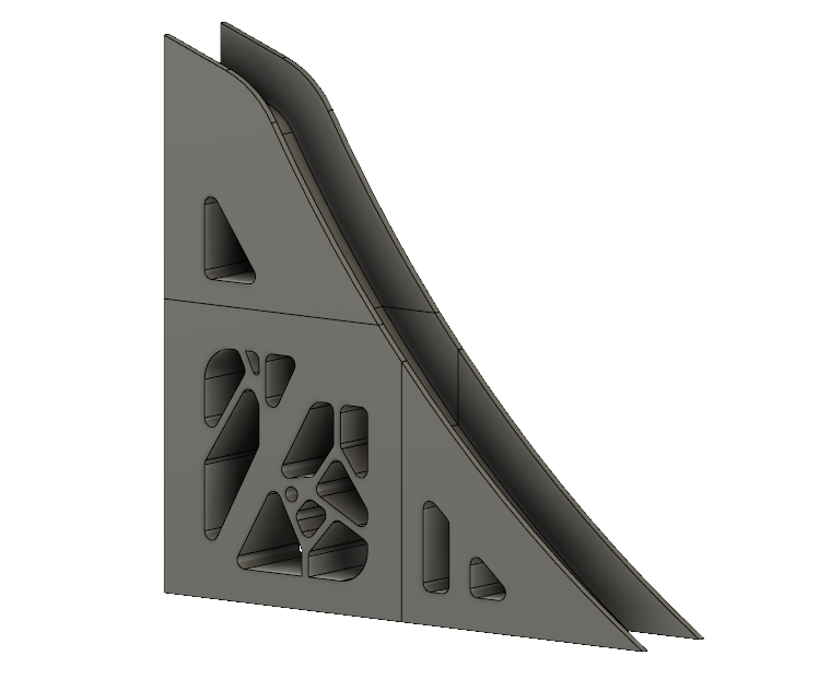
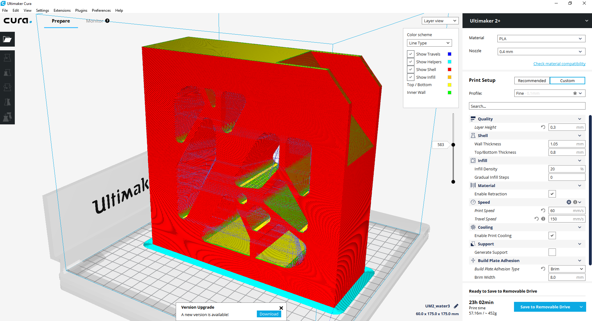
And then started making hollowed parts to decrease material consumption.
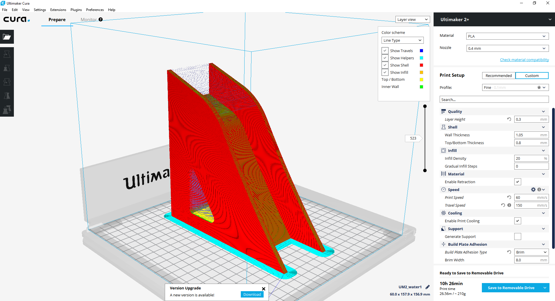
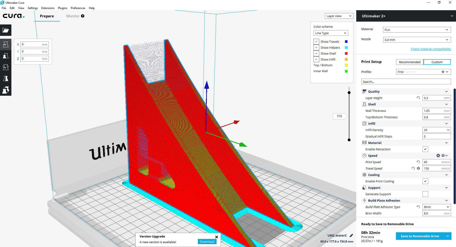
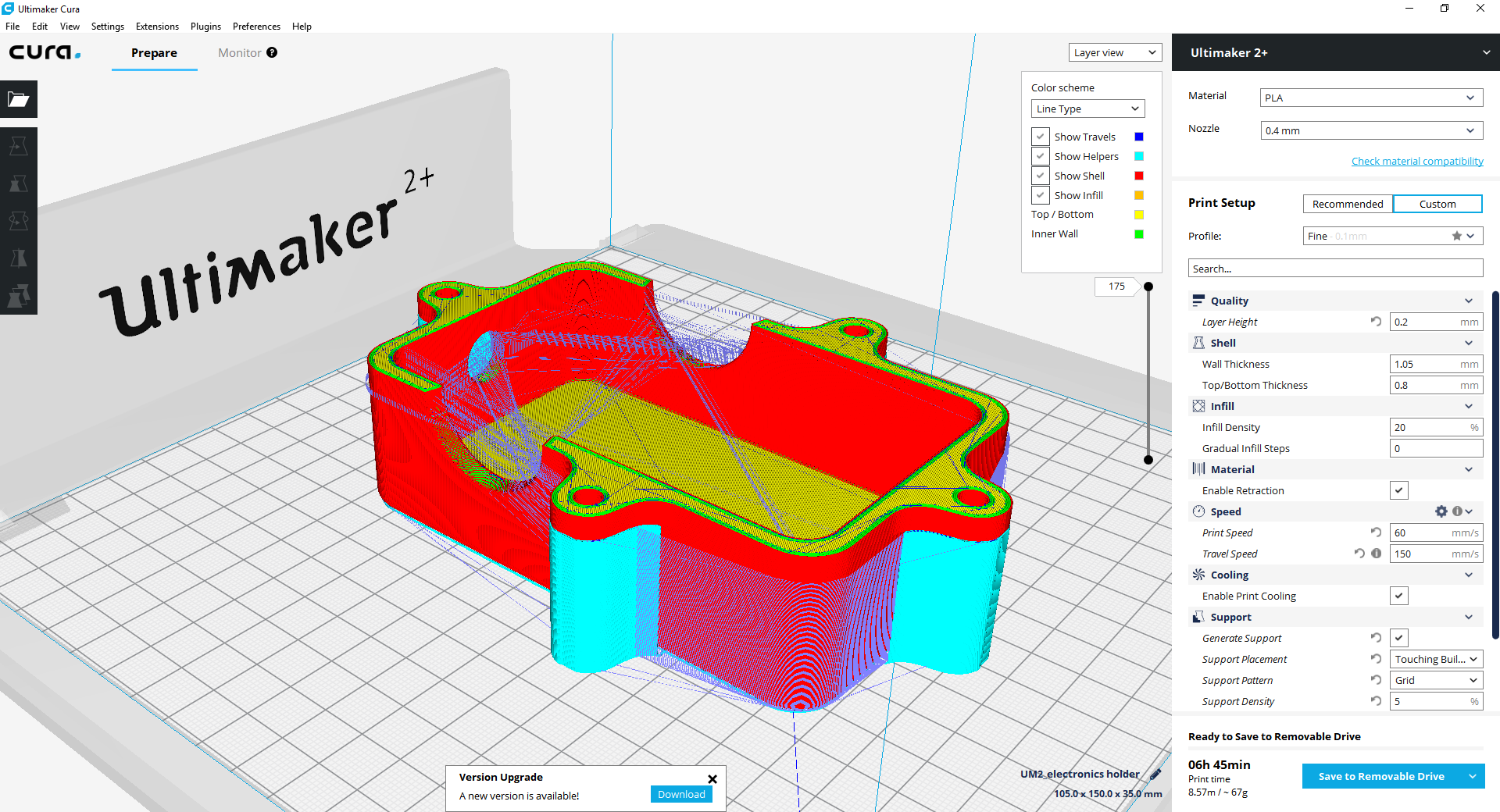
However, the size of the slide was too big for a 3D printer, so I had to divide it into 3 parts.
I started each part simultaneously on a different printers. The biggest part (the middle one) of the slide needed approximately 23 hours and 480g of material.
Cura Settigns for the Slide:
And then, a disaster happened! After the two smaller parts have finished printing and before the big one ended, there was an electricity shutdown that caused the printing to stop. And since the timing was critical and the material consumbtion was high, repeating the job was not a bright option. So, using a caliper, I measured the height that the printed part had reached. Then I went to my design file, created an offset plane with the measured distance from the base surface, then splitted the body using that plane and printed the remaining part (on the same printing settings) to glue it later on to the original unfinished part.
And to assemble the whole slide, I used super-glue as well.
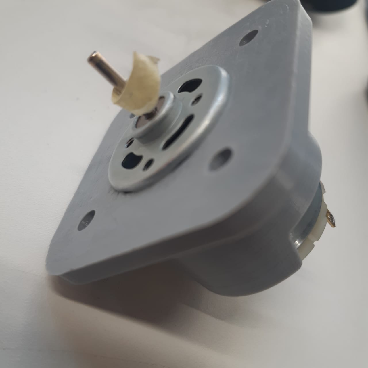
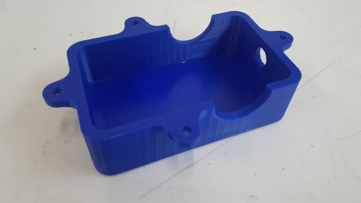
I created two 3D printed mounts, one for the DC motor to mount it to the small house and at a fixed place for the mill to have one degree of freedom only. The other one is a pucket to hold the electronic parts and simplify cable management.
And to assemble the mounts, I used a 4mm diameter screws and nuts.
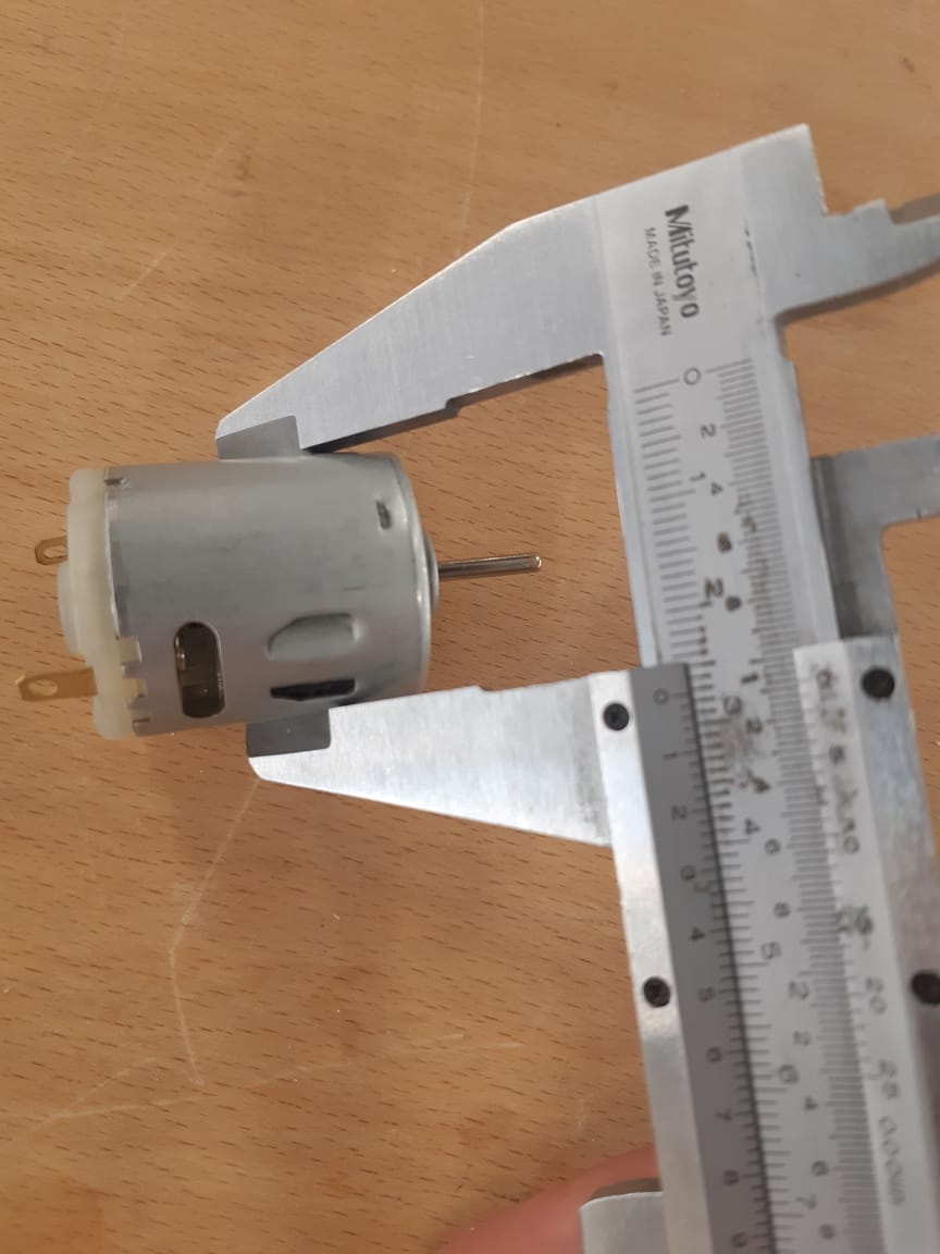
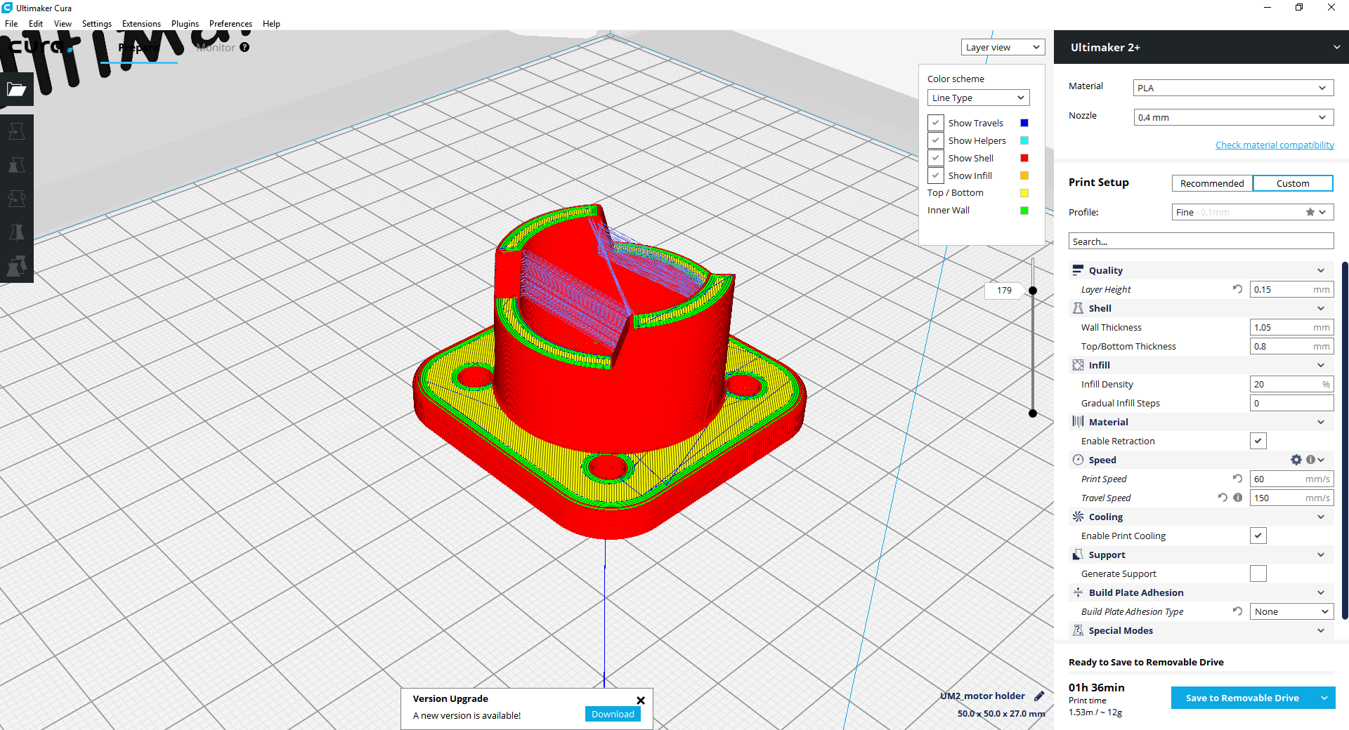
Designing the motor mount, I needed to be accurate at the dimensions as to actually mount the motor, so I used a calliper:
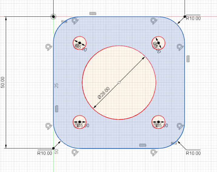
Then on Fusion 360 I sketched my sketch considering those dimensions.
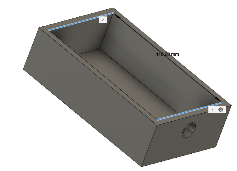
For the electronics mount, it needed to be reasonably bigger than the electronic boards, with a hole for the charger to be in place.
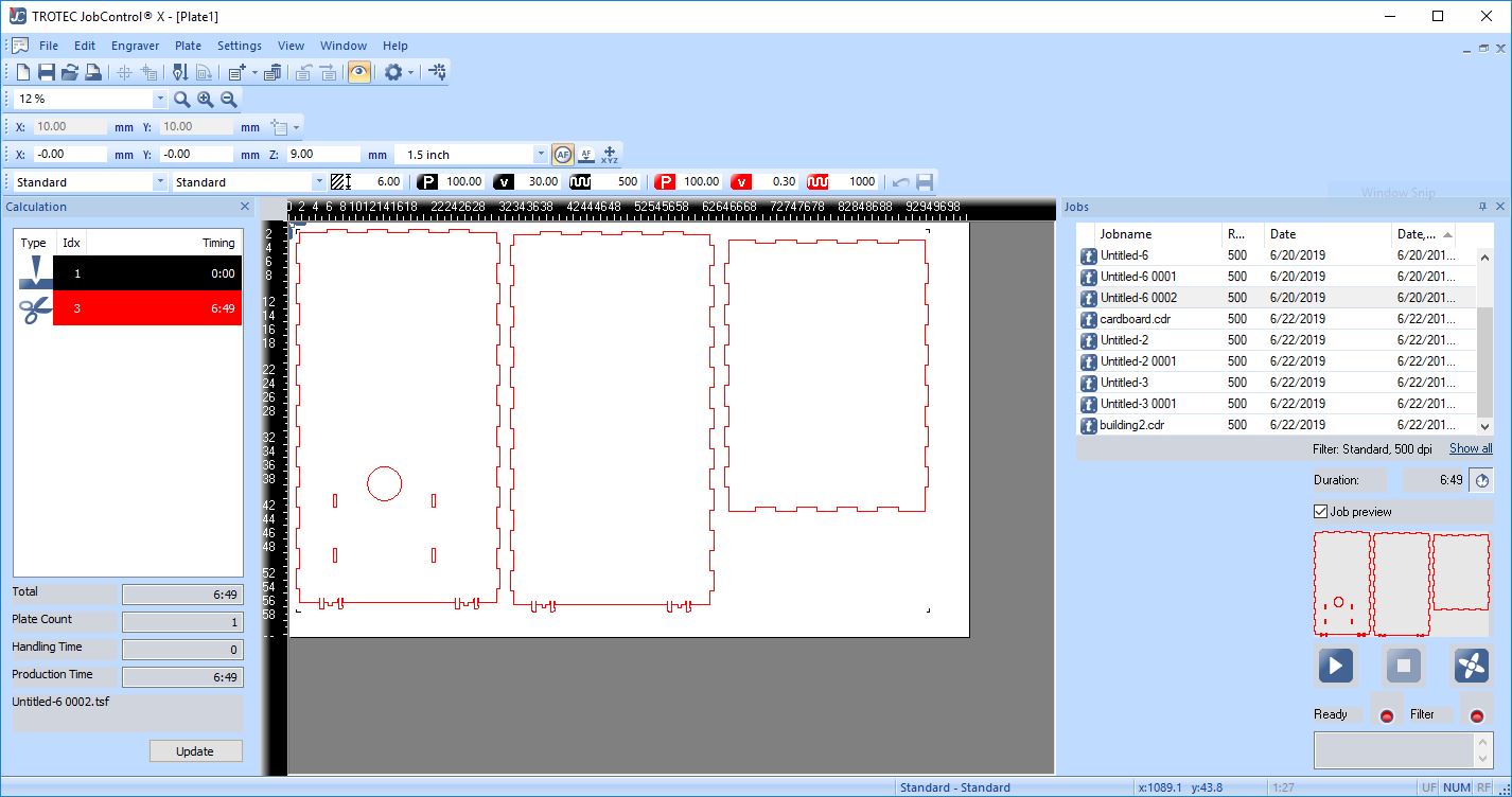
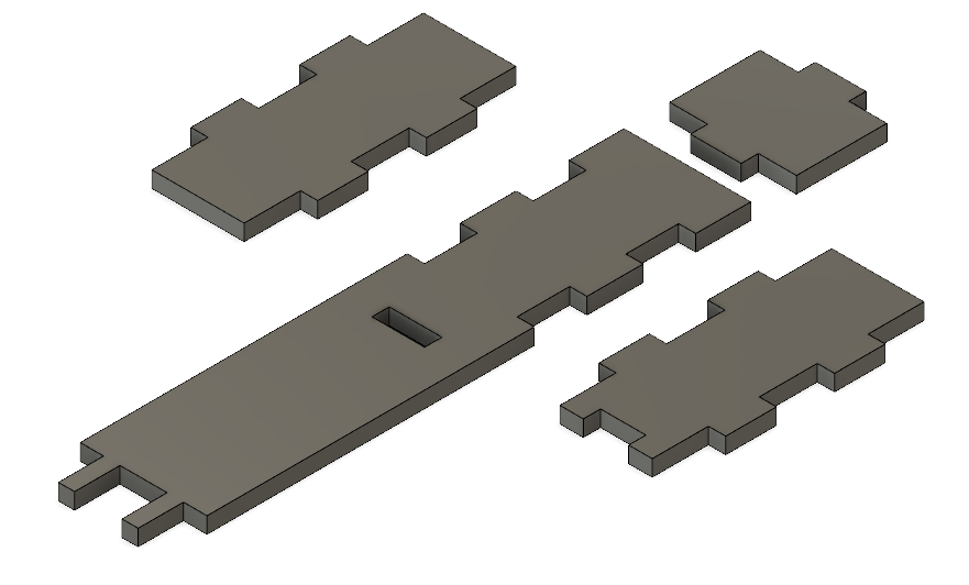
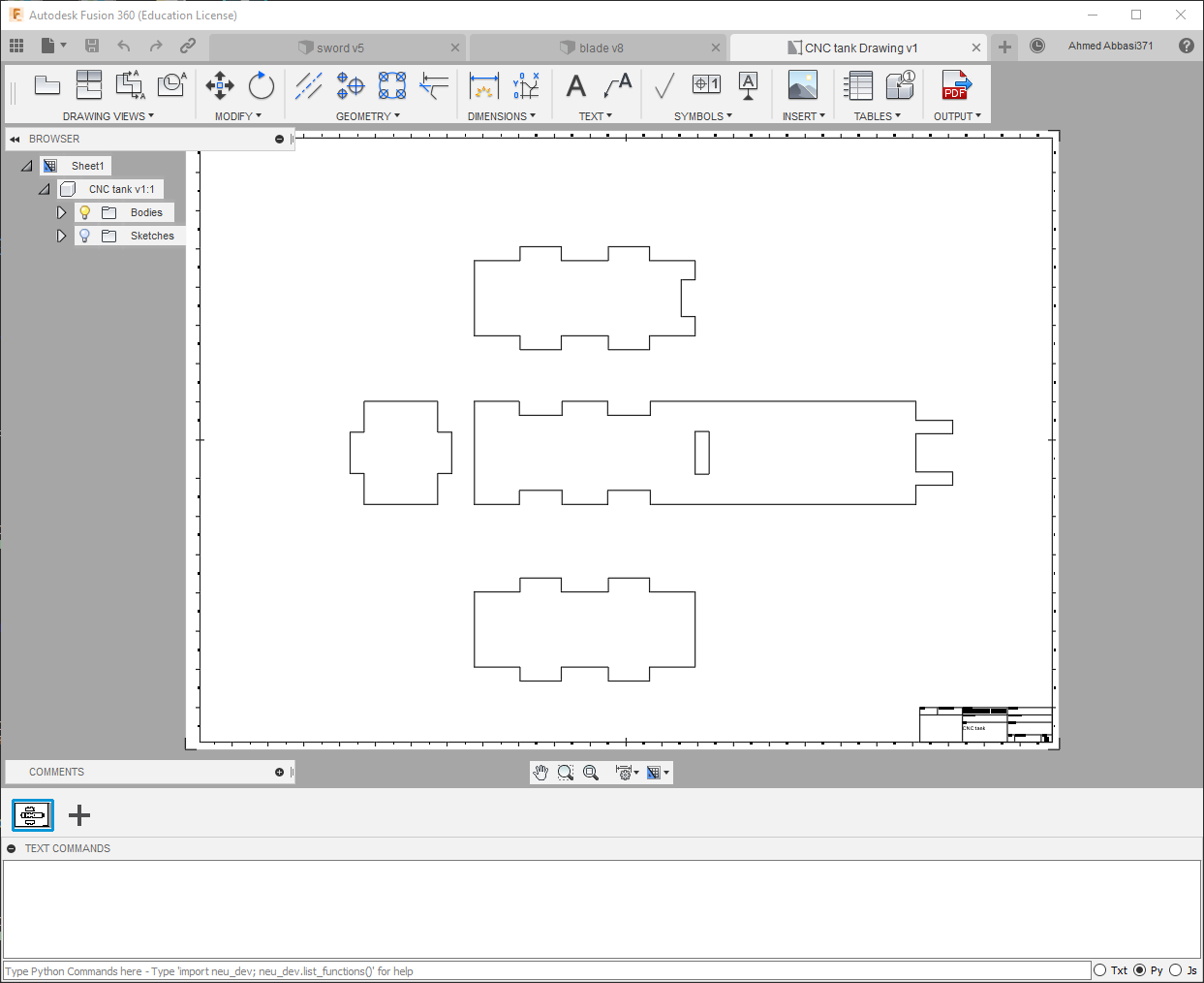
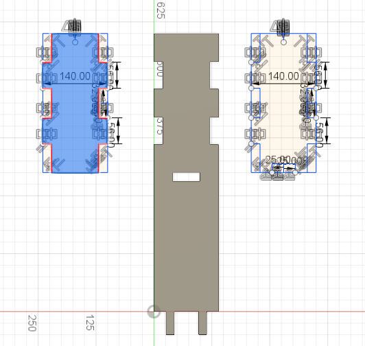
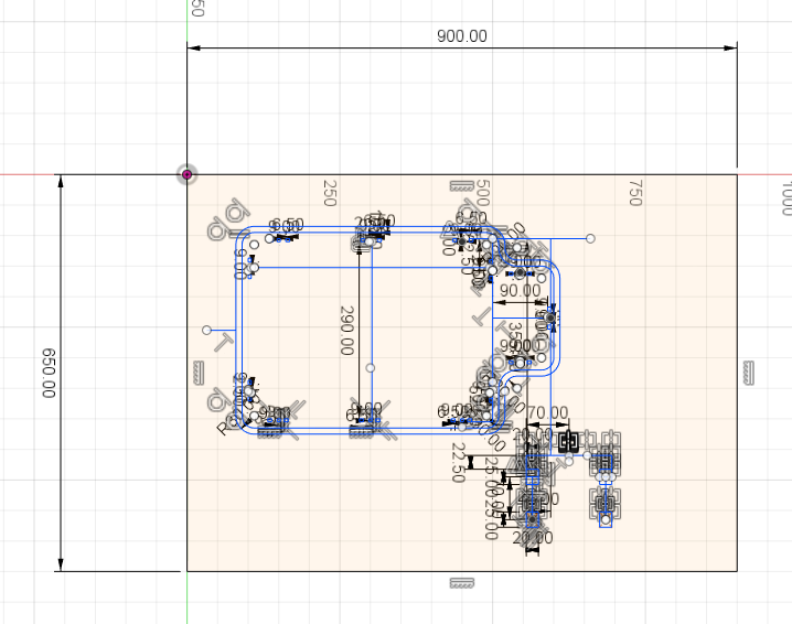
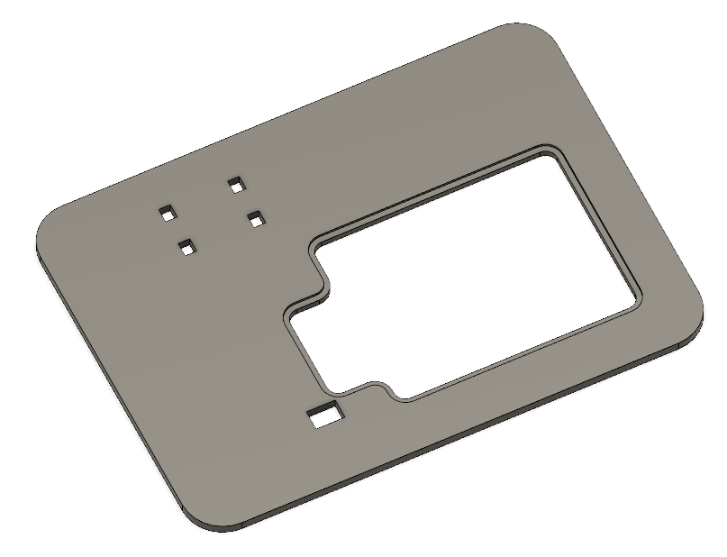
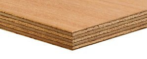
The base plate is a plywood platform that holds everything on top of it. I designed it on Fusion 360 and machined it on the Shopbot CNC. It has a socket in the shape of the building base and a holes design to be able to insert the tower tank in them, and finally a discharge hole for the waste water.
I coppied the design of the building base, I can have something of the same shape and dimensions. Then made an offset for it to make a pocket that would hold the building inside it.
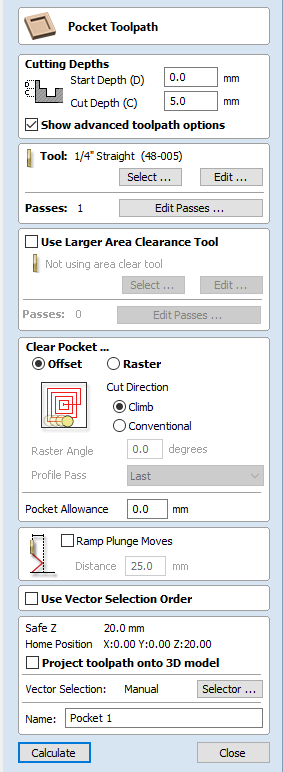
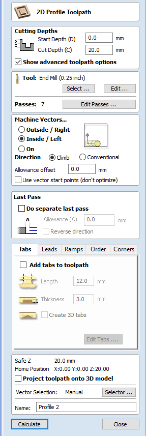
Job Control for Machining the Plate:
The plate needed two toolpaths, one to create the pocket, and another to cut the edges.
At last, when everything was fabricated, I assembled the final product to have my model alive.
An issue I have with my final product is that the water is sliding down the slope, it rushed out instantly as I unplugged the rubber cap because the door is too big. So I tried to place a bottle inside the tank upside down, but fount the stream too shallow and did not move the blades at all!